Table of Contents
Advertisement
SERVICE MANUAL
REVICED
Ver 1.1 1998.08
CD player Section
System
Compact disc digital audio system
Laser diode properties
Material: GaAlAs
Wave length: 780 nm
Emission duration : Continuous
Laser output : Less than 44.6 µW
(This output is the value measured at a
distance of about 200 mm from the objective
lens surface on the optical pick-up block
with 7 mm aperture.)
Spindle speed
200 r/min (rpm) to 500 r/min (rpm) (CLV)
Number of channels
2
Frequency response
20 – 20,000 Hz +1 /–2 dB
Wow and flutter
Below measurable limit
Radio section
Frequency range
FM
87.6 – 107 MHz
(EXCEPT Italian Model)
87.5 – 108 MHz (Italian Model)
AM
531 – 1,602 kHz
IF
FM : 10.7 MHz
AM : 450 kHz
Aerials
FM: Telescopic aerial
AM : Built-in ferrite bar aerial
MICROFILM
Model Name Using
Similar Mechanism
Optical Pick-up Type
Tape Transport Mechanism Type
SPECIFICATIONS
Cassette-corder section
Recording system
4-track 2 channel stereo
Fast winding time
Approx. 120 s (sec.) with Sony cassette C-60
Frequency response
TYPE I (normal): 70 – l0,000 Hz
General
Speaker
Full range: 10 cm (4 in.) dia.,
2.8 ohms, cone type (2)
Outputs
Headphones jack (stereo minijack)
For 16 – 68 ohms impedance headphones
Maximum power output
2.5 W + 2.5 W
Power requirements
For CD radio cassette-corder
230V AC, 50Hz
9V DC, 6 R20 (size D) batteries
Power consumption
AC 20 W
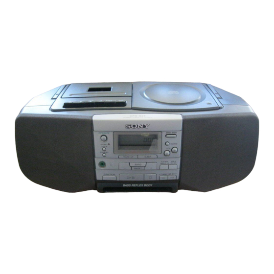
CD RADIO CASSETTE -CORDER
CFD-S27
Australian Model
CD Section
Tape Section
MF-V10-117
Battery life
For CD radio cassette-corder
FM recording
Sony R20P : approx. 13.5 h
Sony alkaline LR20 : approx. 20 h
Tape playback
Sony R20P : approx. 7.5 h
Sony alkaline LR20 : approx. 15 h
CD playback
Sony R20P : approx. 2.5 h
Sony alkaline LR20 : approx. 7 h
Dimensions
Approx. 425 x 160 x 245 mm (w/h/d)
3
3
(16
/
x 6
/
x 9
4
16
projecting parts)
Mass
Approx. 4.0 kg (8 lb. 13 oz) (incl. batteries)
Supplied accessories
AC power cord (1 )
Design and specifications are subject to change
without notice.
AEP Model
UK Model
CFD-S23
KSM-213CDM
3
/
inches) (incl.
4
Advertisement
Table of Contents

Related Manuals for Sony cfd-s27


Summary of Contents for Sony cfd-s27
- Page 1 FM recording Laser diode properties Fast winding time Sony R20P : approx. 13.5 h Material: GaAlAs Approx. 120 s (sec.) with Sony cassette C-60 Wave length: 780 nm Frequency response Sony alkaline LR20 : approx. 20 h Emission duration : Continuous TYPE I (normal): 70 –...
-
Page 2: Table Of Contents
5-7. Schematic Diagram – Main Section (1/2) – PARTS LIST ARE CRITICAL TO SAFE OPERATION. (New Type) ............... 39 REPLACE THESE COMPONENTS WITH SONY PARTS WHOSE PART NUMBERS APPEAR AS SHOWN IN THIS MANUAL OR 5-8. Schematic Diagram – Main Section (2/2) –... - Page 3 LASER DIODE AND FOCUS SEARCH OPERATION CHECK Insert a precision screw driver and push 1. Press CD open knob. SWITCH (S871) 2. Open the lid for CD. 3. Push on SWITCH (S871) as following figure. 4. Confirm the laser diode emission while observing the objecting lens.
-
Page 4: General
SECTION 2 This section is extracted from GENERAL instruction manual. LOCATION OF CONTROLS 9 !º @¡ !¡ @º !ª !• !¶ !§ !∞ !¢ !£ !™ !™ ± button 1 OPR/BATT indicator !£ ≠ button 2 POWER (or OPERATE) button !¢... -
Page 5: Disassembly
SECTION 3 DISASSEMBLY The equipment can be removed using the following procedure. Cabinet (Front) SW board Cabinet (Rear) BATT board, Tuner board, AC inlet board, Power board Cabinet (Upper) Optical pick-up section Main board, CD motor board REC SW board Mechanism deck Note : Follow the disassembly procedure in the numerical order given. -
Page 6: Cabinet (Upper)
3-3. CABINET (UPPER) 4 Screws +BVTP (3X10) 1 Screws +BVTP (3X10) Handle Cabinet (Upper) 2 STOP/EJECT Tape operation buttons Cabinet (Rear) 3-4. OPTICAL PICK-UP SECTION, MECHANISM DECK, MAIN BOARD, 8 Remove solder REC SW BOARD, CD MOTOR BOARD 5 Screws +BVTP (3X10) CD motor board Mechanism deck Optical pick-up... -
Page 7: Adjustments
SECTION 4 ADJUSTMENTS 4-1. MECHANICAL ADJUSTMENTS 4-2. ELECTRICAL ADJUSTMENTS TAPE RECORDER SECTION PRECAUTION Standard Output Level 1. Clean the following parts with a denatured-alcohol-moistened Output terminal HP OUT swab : record/playback head pinch roller load impedance 32Ω erase head rubber belts output signal level 0.25V (–10dB) capstan... - Page 8 0dB = 1 µV TUNER SECTION • Repeat the procedures in each adjustment several times, and the frequency coverage and tracking adjustments should be finally AM Section done by the trimmer capacitors. Function switch : AM Volume : MIN AM IF ADJUSTMENT AM RF signal Adjust for a maximum reading on level meter.
- Page 9 CD SECTION E-F Balance Adjustment This adjustment is to be done when the optical pick-up block is Note on Adjustment replaced. 1. Perform adjustment in test mode. After adjustment, be sure to release test mode. Adjustment Procedure : 2. Perform adjustments in the order given. 1.
- Page 10 Focus Bias Adjustment Focus/Tracking Gain Adjustment This adjustment is to be done when the optical pick-up block is A frequency responce analyzer is necessary in order to perform this replaced. adjustment exactly. However, this gain has a margin, so even if it is slightly off, there is Adjustment procedure : no problem.
- Page 11 VOLT/DIV : 100mV 5. Connect oscilloscope to TP (TO) and TP (VC) on MAIN board. TIME/DIV : 2ms 6. Adjust RV704 on MAIN board so that the waveform is as shown in the figure below. (Tracking gain adjustment) VOLT/DIV : 1V TIME/DIV : 2ms 100mV •...
- Page 12 Adjustment Location : L1 : FM Tracking Adjustment CT1 : FM Tracking Adjustment [TUNER BOARD] (Component side) L4 : AM Frequency Coverage Adjustment L3 : AM Tracking Adjustment CT2 : AM Tracking Adjustment L2 : FM Frequency Coverage Adjustment T1 : FM IF Adjustment CFT1 : AM IF Adjustment RV702 : Focus Gain Adjustment RV704 : Tracking Gain Adjustment...
-
Page 13: Diagrams
SECTION 5 DIAGRAMS 5-1. EXPLANATION OF IC TERMINALS IC801 CXP50716-080Q (SYSTEM CONTROL) Pin No. Pin name Description 1 – 19 SEG 18 – 0 LCD segment output. 20 – 23 COM 3 – 0 LCD common output. VLC1 LCD drive deviced voltage input. VLC2 LCD drive deviced voltage input. - Page 14 Pin No. Pin name Description C-XLAT Serial clock latch output for DSP (IC702). R-MUTE Radio mute signal output. R-DATA Serial data output to PLL (IC3). R-CLK Serial clock output to PLL (IC3). R-CE Chip enable output to PLL (IC3). – Ground.
-
Page 15: Block Diagram
CFD-S27 Circuit Boards Location 5-2. BLOCK DIAGRAM POWER board REC SW board BATT board CD MOTOR board AC INLET board SW board MAIN board TUNER RETAINER board TUNER board • Signal path. : FM : PB : REC : CD –... -
Page 17: Schematic Diagram - Main Section (1/2) - (Former Type)
Refer to page 31 for IC Block Diagrams. CFD-S27 5-4. SCHEMATIC DIAGRAM – MAIN SECTION (1/2) – (FORMER TYPE) Waveforms 1.1 Vp-p 75 kHz IC3 1 VOLT/DIV : 0.2 V AC TIME/DIV : 10 µsec 3.6 Vp-p 4.19 MHz IC801 &™... -
Page 18: Schematic Diagram - Main Section (2/2) - (Former Type)
CFD-S27 5-5. SCHEMATIC DIAGRAM – MAIN SECTION (2/2) – (FORMER TYPE) Refer to page 32 for IC Block Diagrams. Waveforms (PLAY MODE) 5.3 Vp-p 1.0 – 1.4 Vp-p 140.5 µ sec IC701 #¡ IC702 #¡ VOLT/DIV : 200 mV AC... - Page 19 CFD-S27 IC Block Diagrams – MAIN SECTION (1/2) – IC Block Diagrams – MAIN SECTION (2/2) – IC703 BA6198S IC704 SM5877AM IC1 TA2008AN IC701 CXA1782CQ ATCK MUTE ATTENUATION COUNTER MODE FILTER PROCESSOR & LEVEL SHIFT LEVEL SHIFT EMPH T.S.D ATTENUATION PROCESSOR OP-AMP 13.3K...
-
Page 21: Schematic Diagram - Main Section (1/2) - (New Type)
Refer to page 31 for IC Block Diagrams. CFD-S27 5-7. SCHEMATIC DIAGRAM – MAIN SECTION (1/2) – (NEW TYPE) Waveforms 1.1 Vp-p 75 kHz IC3 1 VOLT/DIV : 0.2 V AC TIME/DIV : 10 µsec 3.6 Vp-p 4.19 MHz IC801 &™... -
Page 22: Schematic Diagram - Main Section (2/2) - (New Type)
CFD-S27 Refer to page 32 for IC Block Diagrams. 5-8. SCHEMATIC DIAGRAM – MAIN SECTION (2/2) – (NEW TYPE) Waveforms (PLAY MODE) 5.3 Vp-p 1.0 – 1.4 Vp-p 140.5 µ sec IC701 #¡ IC702 #¡ VOLT/DIV : 200 mV AC... -
Page 23: Exploded Views
SECTION 6 EXPLODED VIEWS NOTE : • -XX, -X mean standardized parts, so they • The mechanical parts with no reference The components identified by mark ! may have some difference from the original number in the exploded views are not or dotted line with mark ! are critical one. -
Page 24: Upper Cabinet Section
6-2. UPPER CABINET SECTION MF-V10-117 KSM-213CDM S871 Ref. No. Part No. Description Remark Ref. No. Part No. Description Remark 3-009-208-01 SPRING, CASSETTE UP 4-951-620-01 SCREW (2.6X8), +BVTP 3-922-112-11 DAMPER * 67 1-666-265-11 REC SW BOARD 3-009-186-41 CABINET (UPPER) 3-009-201-31 HANDLE 3-009-209-01 SPRING, CD UP 3-923-736-01 COVER, CD 1-452-899-11 MAGNET... -
Page 25: Rear Cabinet Section
6-3. REAR CABINET SECTION not supplied ANT1 F902 T901 LCD801 not supplied not supplied The components identified by mark ! or dotted line with mark ! are critical for safety. Replace only with part number specified. Ref. No. Part No. Description Remark Ref. -
Page 26: Mechanism Deck Section (1) (Mf-V10-117)
6-4. MECHANISM DECK SECTION (1) (MF-V10-117) HRP901 HE901 Ref. No. Part No. Description Remark Ref. No. Part No. Description Remark 3-933-010-01 SPRING (S/P), TORSION * 162 3-008-587-01 SLIDER (STOP) 3-933-025-01 SPRING (P), TORSION * 163 3-008-591-01 SLIDER (PAUSE) 3-933-026-01 LEVER (P) 3-933-004-01 CLAW, REEL 3-933-024-01 ROLLER, PINCH * 165... -
Page 27: Mechanism Deck Section (2) (Mf-V10-117)
6-5. MECHANISM DECK SECTION (2) (MF-V10-117) S902 S901 M901 Ref. No. Part No. Description Remark Ref. No. Part No. Description Remark 3-933-029-01 LEVER, ERASING PREVENTION 3-932-993-01 CHASSIS, OUTSERT 3-933-182-01 SPRING, CASSETTE 3-343-358-01 RING, RETAINING 3-932-995-01 GEAR (MID) 3-933-005-01 SPRING (CAM), COMPRESSION X-3371-667-1 CLUTCH ASSY 3-932-997-01 GEAR (CAM) 3-016-349-01 WASHER... -
Page 28: Optical Pick-Up Section (Ksm-213Cdm)
6-6.OPTICAL PICK-UP SECTION (KSM-213CDM) not supplied M702 M701 The components identified by mark ! or dotted line with mark ! are critical for safety. Replace only with part number specified. Ref. No. Part No. Description Remark Ref. No. Part No. Description Remark 2-626-908-01 SHAFT, SLED... -
Page 29: Electrical Parts List
AC INLET BATT SECTION 7 ELECTRICAL PARTS LIST CD MOTOR MAIN NOTE : • Due to standardization, replacements in the • SEMICONDUCTORS In each case, u : µ , for example : The components identified by mark ! parts list may be different from the parts uA.. - Page 30 MAIN Ref. No. Part No. Description Remark Ref. No. Part No. Description Remark C334 1-162-294-31 CERAMIC 0.001uF C744 1-162-286-21 CERAMIC 220PF (NEW TYPE) C745 1-124-902-00 ELECT 0.47uF C335 1-124-443-00 ELECT 100uF C336 1-104-666-11 ELECT 220uF 6.3V C746 1-162-306-11 CERAMIC 0.01uF C340 1-162-294-31 CERAMIC 0.001uF...
- Page 31 MAIN Ref. No. Part No. Description Remark Ref. No. Part No. Description Remark C916 1-162-294-31 CERAMIC 0.001uF Q309 8-729-036-89 TRANSISTOR KTC3198GR-AT C953 1-124-443-00 ELECT 100uF Q310 8-729-036-89 TRANSISTOR KTC3198GR-AT Q311 8-729-036-89 TRANSISTOR KTC3198GR-AT < CONNECTOR > Q312 8-729-037-34 TRANSISTOR KRA107M Q313 8-729-036-77 TRANSISTOR KRC107M CN301...
- Page 32 MAIN Ref. No. Part No. Description Remark Ref. No. Part No. Description Remark R310 1-247-815-91 CARBON 1/4W R755 1-249-429-11 CARBON 1/4W R313 1-249-401-11 CARBON 1/4W R756 1-249-440-11 CARBON 1/4W R314 1-249-399-11 CARBON 1/4W R321 1-249-425-11 CARBON 4.7K 1/4W R757 1-249-439-11 CARBON 1/4W R322 1-249-417-11 CARBON...
- Page 33 MAIN POWER REC SW SW Ref. No. Part No. Description Remark Ref. No. Part No. Description Remark R919 1-249-437-11 CARBON 1/4W < VIBRATOR > R920 1-249-437-11 CARBON 1/4W R921 1-249-437-11 CARBON 1/4W X701 1-760-793-11 VIBRATOR, CERAMIC (16.9344MHz) R922 1-249-437-11 CARBON 1/4W X801 1-767-184-11 VIBRATOR, CERAMIC (4.19MHz)
- Page 34 SW TUNER Ref. No. Part No. Description Remark Ref. No. Part No. Description Remark R814 1-247-843-11 CARBON 3.3K 1/4W 1-126-963-11 ELECT 4.7uF R815 1-249-428-11 CARBON 8.2K 1/4W 1-126-963-11 ELECT 4.7uF R817 1-249-418-11 CARBON 1.2K 1/4W 1-162-839-11 CERAMIC 0.01uF R818 1-249-420-11 CARBON 1.8K 1/4W 1-136-177-00 FILM...
- Page 35 TUNER Ref. No. Part No. Description Remark Ref. No. Part No. Description Remark < FILTER > 1-249-429-11 CARBON 1/4W (FORMER TYPE) 1-236-022-11 FILTER, BAND PASS 1-249-429-11 CARBON 1/4W < IC > 1-249-429-11 CARBON 1/4W 1-249-417-11 CARBON 1/4W 8-759-386-02 IC TA2008AN 1-249-417-11 CARBON 1/4W 8-759-333-33 IC BU2614...
- Page 36 CFD-S27 Ref. No. Part No. Description Remark 1-770-019-11 ADAPTOR, CONVERSION PLUG 3P (UK) 3-859-119-12 MANUAL, INSTRUCTION (ENGLISH, GERMAN) (AEP,UK) 3-859-119-22 MANUAL, INSTRUCTION (FRENCH, SPANISH) (AEP) 3-859-119-32 MANUAL, INSTRUCTION (DUTCH, SWEDISH, PORTUGUESE) (AEP) 3-859-119-42 MANUAL, INSTRUCTION (ITALIAN) (IT) 3-859-119-51 MANUAL, INSTRUCTION (POLISH, RUSSIAN)