Table of Contents
Advertisement
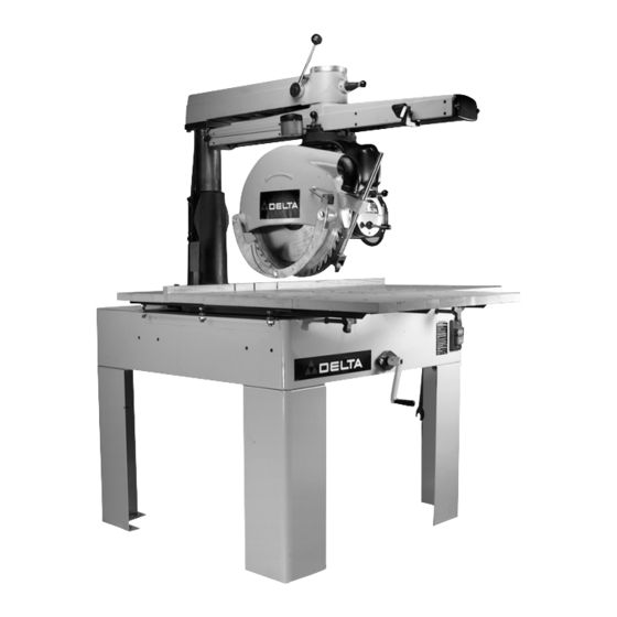
14", 16", and 18"
Long Arm Radial Saws
(Models 33-400, 33-401, 33-402, 33-403,
33-410, 33-411, 33-412, 33-413,
33-420, 33-421, 33-422, 33-423)
PART NO. 424-03-651-0019 - 06-20-05
Copyright © 2004 Delta Machinery
To learn more about DELTA MACHINERY
visit our website at: www.deltamachinery.com.
For Parts, Service, Warranty or other Assistance,
1-800-223-7278 (
1-800-463-3582).
please call
In Canada call
Advertisement
Table of Contents

Related Manuals for Delta 16"


Summary of Contents for Delta 16"
- Page 1 14", 16", and 18" Long Arm Radial Saws (Models 33-400, 33-401, 33-402, 33-403, 33-410, 33-411, 33-412, 33-413, 33-420, 33-421, 33-422, 33-423) PART NO. 424-03-651-0019 - 06-20-05 Copyright © 2004 Delta Machinery To learn more about DELTA MACHINERY visit our website at: www.deltamachinery.com. For Parts, Service, Warranty or other Assistance, 1-800-223-7278 ( 1-800-463-3582).
-
Page 2: Table Of Contents
IMPORTANT SAFETY INSTRUCTIONS ............2 SAFETY GUIDELINES . -
Page 3: Safety Guidelines
SAFETY GUIDELINES - DEFINITIONS It is important for you to read and understand this manual. The information it contains relates to protecting YOUR SAFETY and PREVENTING PROBLEMS. The symbols below are used to help you recognize this information. Indicates an imminently hazardous situation which, if not avoided, will result in death or serious injury. Indicates a potentially hazardous situation which, if not avoided, could result in death or serious injury. -
Page 4: General Safety Rules
READ AND UNDERSTAND ALL WARNINGS AND OPERATING INSTRUCTIONS BEFORE USING THIS EQUIPMENT. Failure to follow all instructions listed below, may result in electric shock, fire, and/or serious personal injury or property damage. 1. FOR YOUR OWN SAFETY, READ THE INSTRUCTION MANUAL BEFORE OPERATING THE MACHINE. -
Page 5: Additional Specific Safety Rules
REMOVE CUT-OFF PIECES AND SCRAPS from the table before starting the saw. The vibration of the machine may cause them to move into the saw blade and be thrown out. After cutting, turn the machine off. Wait for the blade to come to a complete stop before removing any debris. -
Page 6: Functional Description
System. Please refer to its instruction manual for installation guidance. * 460 VOLT OPERATION: If your saw has a dual voltage motor (230/460 volts), and you desire the machine to run at 460 volts, the re-wiring must be done by a qualified electrician and conform to the National Electric Code and all local codes and ordinances. -
Page 7: Unpacking And Cleaning
GUIDE TO PARTS The following is an explanation of the operating controls of the Delta 14", 16" and 18" Radial Arm Saws. All users will benefit by knowing how to set and operate the controls for all cutting operations. To avoid the possibility of damage to the machine and/or injury to the operator, all user’s should become familiar with the operations and the controls before turning the machine “ON’. -
Page 8: Assembly
Remove bolts that fasten the machine to the skid. IMPORTANT: To gain access to the four bolts that fasten the saw to the wooden shipping skid, loosen two table lock knobs (A) Fig. 4. Remove fence (B), angled front table board (C) and at least two table boards (D). - Page 9 CUTTINGHEAD AND CROSS-CUT STOP TO TRACK-ARM 1. Remove two screws (A) and end cap (B) from track- arm, Fig. 8. 2. Hold cuttinghead assembly (D) Fig. 9, with both hands and insert the ball bearings (E) into the track- arm, as shown. Push cuttinghead all the way onto track-arm and tighten clamp knob (F).
- Page 10 1/4-20 weld nuts in the back of the starter box. A cable clamp is supplied to attach the power cord to saw frame. 3. Fig. 14 illustrates the starter box assembled to the base.
- Page 11 Using the spanner wrench (E) Fig. 18 as a feeler gauge, raise or lower track-arm by turning elevating handle (F) Fig. 19 until saw arbor (B) just touches wrench (E). DO NOT RAISE OR LOWER TRACK-ARM ANY FURTHER UNTIL LEVELING ADJUSTMENT IS COMPLETED.
- Page 12 IMPORTANT: To prevent arbor nut from spinning when blade stops, place the 1-1/16" wrench (C) Fig. 23 on flats of arbor and firmly tighten arbor nut (A) with the 1-5/8" box end spanner wrench (D) (left handed thread). Firmly tighten set screw (E). Remove screw (F) Fig.
-
Page 13: Operation
Every Delta Radial Arm Saw is thoroughly tested, inspected and accurately aligned before leaving the factory and, when delivered, is ready for operation after it is assembled. However, regardless of the care with which this or any piece of fine machinery is manufactured, inspected and shipped, it is possible that rough handling in shipment, or wear over a period of time may make minor adjustments necessary. - Page 14 2. Remove end plate and cross cut stop from track- arm. 3. Remove yoke assembly from track-arm and place yoke assembly (C) Fig. 32 on saw table. 4. Pull yoke clamp handle (A) to the position shown in Fig. 32 to loosen, and loosen set screw (D) one turn only.
- Page 15 ADJUSTING TRACK RODS Each track rod (A, B, C, D) Fig. 34 can be adjusted individually to present a new bearing surface. Adjust the track rods one at a time as follows: DISCONNECT MACHINE FROM POWER SOURCE. 1. Remove end cap (E) Fig. 35, cross-cut stop (F) and cutterhead assembly (G), from the track-arm (Fig.
- Page 16 Remove blade guard and place saw blade in cut-off position over fixed portion of table. Place a square (A) Fig. 36, against saw blade. Be sure square is on the table surface, and between the gullets of the teeth, not against the saw teeth.
- Page 17 CAUTION: Do not attempt to rotate completely. Notice that the entire track also moves. When saw blade tracks evenly against steel square, tighten clamp handle (G) Fig. 40 and center cap screw (E) Fig. Check pointer and adjust to 0 degrees, if necessary.
- Page 18 1. Cross-cut a board and see on which side of the cut board saw teeth marks appear. 2. If saw teeth marks appear on the right side, the back end of the saw blade must be shifted toward left side.
-
Page 19: Adjusting Blade Guard
ADJUSTING BLADE GUARD DISCONNECT MACHINE FROM POWER SOURCE. On all ripping and plowing operations, the back part of the blade guard is lowered so that it just clears the material. This will prevent the material from being lifted off the table. Also, lower the kickback rod (A) Fig. 46, so that the kickback fingers are 1/8"... - Page 20 USING A TABLE EXTENSION When a table extension more than 24 inches long is attached to the saw, a sturdy outrigger support should be provided or the stand or bench must be secured to the floor.
-
Page 21: Miter Cutting
The workpiece is placed on the table and butted against the fence. The saw blade should be clear of the fence and table when the machine is turned on. Then the saw blade is lowered until it lightly cuts into the table surface. -
Page 22: Compound Miter Cutting
The cutting-head is positioned on the out-rip scale to the desired setting and clamped in position. The workpiece is fed from the left side of the saw. Fig. 56 shows a typical out-ripping operation on the radial saw. IN-RIPPING In-ripping involves all of the general conditions stated under RIPPING. -
Page 23: Constructing A Push Stick
CONSTRUCTING A PUSH STICK When ripping work less than 4 inches wide, a push stick should be used to complete the feed and could easily be made from scrap material by following the pattern shown in Fig. 58. -
Page 24: Troubleshooting
All Delta Machines and accessories are manufactured to high quality standards and are serviced by a network • of Porter-Cable Delta Factory Service Centers and Delta Authorized Service Stations. To obtain additional information regarding your Delta quality product or to obtain parts, service, warranty assistance, or the location of the nearest service outlet, please call 1-800-223-7278 (In Canada call 1-800-463-3582). -
Page 25: Accessories
A complete line of accessories is available from your Delta Supplier, Porter-Cable • Delta Factory Service Centers, and Delta Authorized Service Stations. Please visit our Web Site for the name of your nearest supplier. Since accessories other than those offered by Delta have not been tested with this product, use of such accessories could be hazardous. - Page 26 NOTES...
- Page 27 NOTES...
- Page 28 Phone: (604) 420-0102 Fax: (604) 420-3522 The following are trademarks of PORTER-CABLE • DELTA (Las siguientes son marcas registradas de PORTER-CABLE • DELTA S.A.) (Les marques suivantes sont des marques de fabriquant de la PORTER-CABLE • DELTA): Auto-Set Contractor’s Saw II™, Delta ®...