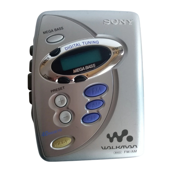
Sony Walkman WM-FX277 Service Manual
Radio cassette player
Hide thumbs
Also See for Walkman WM-FX277:
- Service manual (24 pages) ,
- Operating instructions (2 pages) ,
- Operating instructions (2 pages)
Table of Contents
Advertisement
Advertisement
Table of Contents

Related Manuals for Sony Walkman WM-FX277


Summary of Contents for Sony Walkman WM-FX277
-
Page 1: Specifications
WM-FX277 SERVICE MANUAL E Model Chinese Model Ver 1.0 2001.03 Model Name Using Similar Mechanism MD Mechanism Type MF-WMFX241-114 SPECIFICATIONS RADIO CASSETTE PLAYER Sony Corporation 9-927-695-31 2001C0200-1 Audio Entertainment Group © 2001.3 General Engineering Dept. -
Page 2: Table Of Contents
WM-FX277 TABLE OF CONTENTS Specifications ................1 Flexible Circuit Board Repairing • Keep the temperature of the soldering iron around 270°C during 1. SERVICING NOTE repairing............3 • Do not touch the soldering iron on the same conductor of the circuit board (within 3 times). -
Page 3: Servicing Note
WM-FX277 SECTION 1 SERVICING NOTE In case of adjusting Tape Speed, you can easily to adjust RV601 by removing 7 claws on Window (LCD) and itself as shown in the figure. 1.Insert the precision screwdriver (Cover a point by cloth) in to the slit at claw. 2.Remove the window(LCD). -
Page 4: Disassembly
WM-FX277 SECTION 3 DISASSEMBLY • The equipment can be removed using the following procedure. Cassette holder ASSY Main board Mechanism deck Belt, Capstan/reel motor (M601), Magnetic head (Playback) (HP601) Cabinet (Front) Cassette holder Note : Follow the disassembly procedure in the numerical order given. 3-1. -
Page 5: Mechanism Deck
WM-FX277 3-3. MECHANISM DECK Mechanism deck 1 Claws Cassette holder ASSY 3-4. BELT, CAPSTAN/REEL MOTOR (M601), MAGNETIC HEAD (PLAYBACK)(HP601) 3 Screws (M1.4) 5 Screws (M1.4) 4 Capstan/reel motor Mechanism deck (M601) 6 magnetic head (PLAYBACK) (HP601) 1 Claw 2 Belt Stopper... -
Page 6: Cassette Holder
WM-FX277 3-5. CASSETTE HOLDER 2 Move the hinge away from projection Hinge Projection Projection 3 Move the hinge away from projection Hinge Projection Cabinet (center) Projection Hinge Hinge 4 Spring (torsion) Cassette holder CAUTIONS DURING ASSEMBLY Insert the spring (torsion) to the L shape slot as shown in the figure. 2,3 Insert the hinge of the “Cassette holder ”. -
Page 7: Adjustments
WM-FX277 SECTION 4 ADJUSTMENTS 4-1. MECHANICAL ADJUSTMENTS 4-2. ELECTRICAL ADJUSTMENTS PRECAUTION PRECAUTION 1. Clean the following parts with a denatured-alcohol-moistened • Supplied voltage : 2.5V. swab : • Switch and control position playback head pinch roller MEGA BASS (S709) : OFF capstan rubber belt VOLUME control (RV301) : maximum... - Page 8 WM-FX277 • Repeat the procedures in each adjustment several times, and the 0 dB = 1µV TUNER SECTION frequency coverage and tracking adjustments should be finally AM section done by the trimmer capacitors. no mark : 10kHz step BAND : AM <...
- Page 9 WM-FX277 Adjustment Location : L3 : FM Frequency Coverage Adjustment [MAIN BOARD] (SIDE A) L2 : FM tracking Adjustment L1 : AM Tracking Adjustment T1 : AM IF Adjustment L4 : AM Frequency Coverage Adjustment CT1 : AM Tracking Adjustment...
-
Page 10: Diagrams
WM-FX277 SECTION 5 DIAGRAMS 5-1. EXPLANATION OF IC TERMINALS IC702 LC72348W-9A36 SYSTEM CONTROL Pin No. Pin name Descliption XOUT Crystal oscillator output (75kHz). TEST2 – Not used (Ground). Key input. Key input. Key input. Key input. Key output. Key output. Key output. -
Page 11: Block Diagram
WM-FX277 5-2. BLOCK DIAGRAMS • Abbreviation : Mexican : Chinese : Indication of country of origin (ST/FM MONO) : No Indication of country of origin 5E, 6E : Indication of country of origin (DX/LOCAL) : Taiwan • Signal path. -
Page 12: Printed Wiring Boards - Main Section (Side A)
WM-FX277 5-3. PRINTED WIRING BOARDS – MAIN SECTION (SIDE A) – Semiconductor Location Ref. No. Location MAIN BOARD (SIDE A) IC301 IC701 IC702 Q301 Q501 Q502 Q701 X701 1-680-658- (12) Note: • X : parts extracted from the component side. •... -
Page 13: Printed Wiring Boards - Main Section (Side B)
WM-FX277 5-4. PRINTED WIRING BOARDS – MAIN SECTION (SIDE B) – DRY BATTERY SIZE "AA" Semiconductor (IEC DESIGNATION R6) 2PCS, 3V Location Ref. No. Location MAIN BOARD (SIDE B) D401 D703 B-10 Q401 J301 S702 TUNING+ LCD701 LIQUID CRYSTAL DISPLAY PANEL S705 TUNING–... -
Page 14: Schematic Diagram
WM-FX277 5-5. SCHEMATIC DIAGRAM Refer to page 15 for Notes. Refer to page 15 for Waveforms. Refer to page 16 for IC Block Diagrams. - Page 15 WM-FX277 Note on Schematic Diagram: MAIN SECTION Waveforms • All capacitors are in µF unless otherwise noted. pF: µµF 50 WV or less are not indicated except for electrolytics and tantalums. • All resistors are in Ω and W or less unless otherwise specified.
-
Page 16: Ic Block Diagrams
WM-FX277 • IC BLOCK DIAGRAMS IC1 TA2111F-(EL) Φ Φ DECODER RF AMP DIVIDER AF BUFFER ST/MONO MUTE FM/AM LEVEL AM IF FM IF RF AMP IC301 LB8115W-NA-TLM 48 47 46 45 44 43 FREQ PRE DRIVER CARC. FWD/ OPERATION LOGIC VOLTAGE OPERATION PLUSE DET... -
Page 17: Exploded Views
WM-FX277 SECTION 6 EXPLODED VIEWS NOTE : • Hardware (# mark) list and accessories and packing • -XX, -X mean standardized parts, so they materials are given in the last of this parts list. may have some difference from the original •... -
Page 18: Mechanism Deck Section (Mf-Wmfx241-114)
WM-FX277 6-2. MECHANISM DECK SECTION (MF-WMFX241-114) supplied supplied not supplied supplied supplied supplied supplied supplied M601 HP601 Ref. No. Part No. Description Remark Ref. No. Part No. Description Remark 3-920-990-01 SPRING (UD), COMPRESSION X-3369-749-1 PINCH LEVER (N) ASSY 3-921-335-01 WASHER, LEVER X-3372-619-1 WHEEL ASSY (SP), CAPSTAN 3-019-778-01 SLEEVE (MS) 3-703-816-73 SCREW (M1.4), SPECIAL HEAD... -
Page 19: Electrical Parts List
WM-FX277 SECTION 7 MAIN ELECTRICAL PARTS LIST NOTE : • Due to standardization, replacements in the • Items marked “ * ”are not stocked since they When indicating parts by reference num- parts list may be different from the parts are seldom required for routine service. - Page 20 WM-FX277 MAIN Ref. No. Part No. Description Remark Ref. No. Part No. Description Remark C607 1-125-838-11 CERAMIC CHIP 2.2uF 6.3V 1-414-760-21 FERRITE C701 1-164-361-11 CERAMIC CHIP 0.047uF L401 1-414-760-21 FERRITE C702 1-107-826-11 CERAMIC CHIP 0.1uF L702 1-412-995-21 INDUCTOR 22uH C703 1-162-917-11 CERAMIC CHIP 15PF C704...
- Page 21 WM-FX277 MAIN Ref. No. Part No. Description Remark Ref. No. Part No. Description Remark R401 1-216-845-11 METAL CHIP 100K 1/16W <VIBRATOR> R402 1-216-864-91 SHORT R403 1-216-821-11 METAL CHIP 1/16W 1-795-233-11 FILTER, CERAMIC(10.7MHz) R404 1-216-835-11 METAL CHIP 1/16W X701 1-760-130-11 VIBRATOR, CRYSTAL(75kHz) (E,9E,TW,CH) X701 1-781-592-11 VIBRATOR, CRYSTAL(75kHz) (5E,6E,MX) R501...
- Page 22 WM-FX277 REVISION HISTORY Clicking the version allows you to jump to the revised page. Also, clicking the version at the upper right on the revised page allows you to jump to the next revised page. Ver. Date Description of Revision 2001.03...