Table of Contents
Advertisement
Advertisement
Table of Contents

Related Manuals for Sinclair SCV-50EA


Summary of Contents for Sinclair SCV-50EA
- Page 1 AIR-COOLED MINI CHILLER UNIT SERVICE MANUAL SCV-xxEA AIR CONDITIONING...
-
Page 2: Table Of Contents
Content 1. Outdoor units lineup ............1 2.Features ................2 3. Description of main components ........6 4. Specifications ..............8 5. Dimensions ..............12 6. Piping Diagram ..............13 7. Wiring Diagram ............... 14 ... -
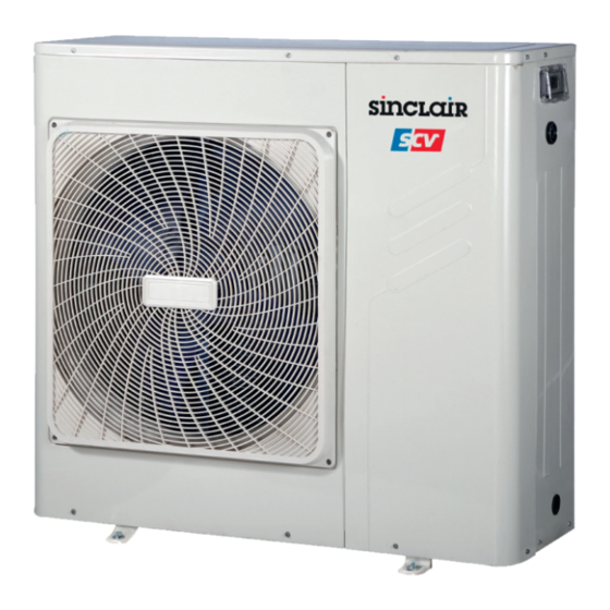
Page 3: Outdoor Units Lineup
1. Outdoor units lineup SCV-50EA, SCV-70EA Power Supply Compressor Heat Hydraulic Model Capacity A/C mode Refrigerant (V/Ph/Hz) type exchanger module SCV-50EA 220-240/1 /50 5.0kW DC Inverter Plate type Heat pump Built-in R410A SCV-70EA 220-240/1/50 7.0kW DC Inverter Plate type Heat pump... -
Page 4: Features
2.Features 2.1 High efficient DC inverter compressor Full DC inverter mini chiller adopts highly intelligent inverter-driven compressor. This advanced technology enables the output of the outdoor unit to be modulated by the real heat load demands.. This advanced system ensures precise temperature regulation and highly efficient energy usage, making a significant contribution to limiting the impact on the environment. - Page 5 2.4 High efficiency 3.39 3.31 3.21 3.23 3.20 3.11 10kW 12kW 14kW 16kW 3.30 3.31 3.24 3.25 10kW 12kW 14kW 16kW .5 Wide operation temperature range Stable and safe running at wide ambient temperature range, cooling performance from -5 ˚C to 46˚C, heating from -15˚C to 27˚C.
- Page 6 a. Metallic protective cabinet with rustproof polyester paint; b. Built-in with voltage protection, current protection, anti-freezing protection, water flow protection and etc., effectively guarantee the system to work safely. 2.7 User friendly remote control Switch SW4_1(10kW) or SW3_1(12-16kW) on the PCB to ON to enable the following remote control functions.
- Page 7 Fast respond resulting in higher efficiency and improved reliability. 100% 2.11 Water pump starts/stops compulsory function Press “Check” button for 3 seconds to start the water pump operating when the unit is standby. Press “Check” button for 3 seconds again to stop the water pump.
-
Page 8: Description Of Main Components
3. Description of main components Structure Panels and base are made from galvanized steel plate painted with epoxy power to ensure total resistance to atmospheric pollution, condensate collection pan as standard. Condenser coils: The coils are made from high performance and seamless copper tuber and high surface area aluminum fins to ensure optimum heat exchange capability. - Page 9 10~16KW 1 Operation panel 11 Electrical panel 12 High pressure switch 2 Water manometer 13 4-ways valve 3 Automatic discharge valve 4 Axial-flow fan 14 Expansion tank 5 Differential pressure switch 15 Pump 6 Condenser 16 Low pressure switch 17 Storage tank 7 Accumulater 18 Compressor 8 Security discharge...
-
Page 10: Specifications
4. Specifications Model SCV-50EA SCV-70EA Power supply V-Ph-Hz 220-240, 1, 50 220-240, 1, 50 Capacity Cooling*(1) Input 1.55 2.25 Capacity 6.57 7.88 Cooling*(2) Input 1.27 1.84 Capacity Heating*(3) Input Capacity 6.32 8.29 Heating*(4) Input 1.52 2.13 EER*(1) kW/kW 3.23 3.11... - Page 11 2. Heating: (*3) warm water inlet/outlet temperature: 40/45°C,outdoor ambient temperature 7°C DB/6°C WB . (*4) warm water inlet/outlet temperature: 30/35°C,outdoor ambient temperature 7°C DB/6°C WB . 3. It is tested 1m away in front of the unit in a semi-anechoic room(sound pressure). 4.
- Page 12 1. Cooling: (*1) chilled water inlet/outlet temperature: 12/7°C,outdoor ambient temperature 35°C DB. (*2) chilled water inlet/outlet temperature: 23/18°C,outdoor ambient temperature 35°C DB. 2. Heating: (*3) warm water inlet/outlet temperature: 40/45°C,outdoor ambient temperature 7°C DB/6°C WB . (*4) warm water inlet/outlet temperature: 30/35°C,outdoor ambient temperature 7°C DB/6°C WB . It is tested 1m away in front of the unit in a semi-anechoic room(sound pressure).
- Page 13 Note: Specifications are based on the following conditions: 1. Cooling: (*1) chilled water inlet/outlet temperature: 12/7°C,outdoor ambient temperature 35°C DB. (*2) chilled water inlet/outlet temperature: 23/18°C,outdoor ambient temperature 35°C DB. 2.Heating: (*3) warm water inlet/outlet temperature: 40/45°C,outdoor ambient temperature 7°C DB/6°C WB . (*4) warm water inlet/outlet temperature: 30/35°C,outdoor ambient temperature 7°C DB/6°C WB .
-
Page 14: Dimensions
5. Dimensions SCV-50EA, SCV-70EA (Unit: mm) SCV-100EA, SCV-120EA, SCV-140EA, SCV-160EA (Unit : mm) -
Page 15: Piping Diagram
6. Piping Diagram SCV-50EA, SCV-70EA HEAT PUMP 1 compressor 6 electronic expansive valve 11 accumulator 2 high pressure switch 7 liquid receiver 12 low pressure switch 3 4-way value(only HEAP PUMP) 8 plate heat exchanger 13 crankcase heater 4 condenser... -
Page 16: Wiring Diagram
7 . Wiring Diagram SCV-50EA, SCV-70EA... - Page 17 SCV-100EA...
- Page 18 SCV-120EA, SCV-140EA, SCV-160EA...
-
Page 19: Electric Characteristics
8. Electric Characteristics Outdoor Unit Power Supply Compressor Model Voltage Phase Min. Max. TOCA SCV-50EA 50Hz 220~240V 198V 264V 10.1 14.6 29.5 0.195 1.65 264V 10.1 15.6 29.5 0.195 1.65 SCV-70EA 50Hz 220~240V 198V SCV-100EA 50Hz 220~240V 198V 264V 15.1 25.0... -
Page 20: Capacity Tables
9. Capacity Tables SCV-50EA Cooling Ambient temp.(℃) 21.00 25.00 30.00 35.00 40.00 46.00 Chilled water outlet temp. (℃) 5.00 5.60 1.37 4.10 5.27 1.41 3.75 4.97 1.45 3.43 4.70 1.50 3.14 4.40 1.57 2.80 4.05 1.65 2.46 6.00 5.79 1.39 4.17... - Page 21 SCV-70EA Cooling Ambient temp.(℃) 21.00 25.00 30.00 35.00 40.00 46.00 Chilled water outlet temp. (℃) 5.00 7.84 1.98 3.95 7.38 2.04 3.61 6.96 2.11 3.31 6.58 2.17 3.03 6.17 2.28 2.70 5.67 2.39 2.37 6.00 8.10 2.01 4.03 7.62 2.07 3.67 7.18 2.14...
- Page 22 SCV-100EA Cooling Ambient temp.(℃) 21.00 25.00 30.00 35.00 40.00 46.00 Chilled water outlet temp. (℃) 5.00 11.20 2.60 4.31 10.54 2.68 3.94 9.95 2.76 3.60 9.40 2.85 3.30 8.81 2.99 2.95 8.10 3.14 2.58 6.00 11.57 2.64 4.39 10.89 2.72 4.00 10.26 2.80...
- Page 23 SCV-120EA Cooling Ambient temp.(℃) 21.00 25.00 30.00 35.00 40.00 46.00 Chilled water outlet temp. (℃) 5.00 12.54 2.98 4.21 11.81 3.07 3.85 11.14 3.16 3.52 10.53 3.26 3.23 9.86 3.42 2.88 9.08 3.60 2.52 6.00 12.96 3.02 4.29 12.19 3.12 3.91 11.49 3.21...
- Page 24 SCV-140EA Cooling Ambient temp.(℃) 21.00 25.00 30.00 35.00 40.00 46.00 Chilled water outlet temp. (℃) 5.00 13.99 3.43 4.07 13.18 3.54 3.72 12.43 3.65 3.41 11.75 3.76 3.12 11.01 3.95 2.79 10.13 4.15 2.44 6.00 14.47 3.49 4.15 13.61 3.60 3.78 12.83 3.71...
- Page 25 SCV-160EA Cooling Ambient temp.(℃) 21.00 25.00 30.00 35.00 40.00 46.00 Chilled water outlet temp. (℃) 5.00 16.23 3.99 4.07 15.29 4.11 3.72 14.42 4.24 3.40 13.63 4.37 3.12 12.77 4.59 2.78 11.75 4.82 2.44 6.00 16.78 4.05 4.14 15.79 4.18 3.78 14.88 4.31...
-
Page 26: Operation Limits
10. Operation Limits COOLING 4 5 7 DELIVERY WATER TEMPERATURE HEATING DELIVERY WATER TEMPERATURE a) Ethylene Glycol Solutions Water and ethylene glycol solutions used as a thermal vector in the place of water reduce the performance of the unit. Multiply the performance figures by the values given in the following table. Freezing point (°C) Percentage of ethylene glycol in weight 0.98... - Page 27 Note: During winter leaving the unit unused, please drain water out completely from unit if no anti-freeze were charged into pipeline, or keep power on (at standby or off status) and ensure that water is contained inside of unit. When ambient temperature lower 5 , ℃...
-
Page 28: Water Pressure Drop
11. Water Pressure Drop SCV-50EA, SCV-70EA SCV-100EA Heat exchanger pressure drop (water side) 研发提供... - Page 29 SCV-120EA SCV-140EA...
- Page 30 SCV-160EA...
-
Page 31: Sound Level
12. Sound Level O u t d o o r U n i t M i c r o 1 . 4 m 1 . 0 m Model Noise level (dB(A)) SCV-50EA SCV-70EA SCV-100EA SCV-120EA SCV-140EA SCV-160EA Note: 1).High/low air flow of outdoor fan motor. -
Page 32: Installation
13. Installation a) Installation of general information General warning These units have been designed to chilled and hot water and must be used in applications compatible with their performance characteristics; these appliances are designed for residential or similar applications. Incorrect installation, regulation and maintenance or improper use absolves the manufacturer from all liability, whether contractual or otherwise, for damage to people, animals or things. - Page 33 b) Installation of outdoor unit Choice of installation site Before installing the unit, agree with the customer the site where it will be installed, taking the following points into consideration: - check that the fixing points are adequate to support the weight of the unit. - pay scrupulous respect to safety distances between the unit and other equipment or structures to ensure that air entering the unit and discharged by the fans is free to circulate.
- Page 34 Installation space (units: mm) Since the gravity center of the unit is not at its physical center, so please be careful when lifting it with a sling. Never hold the inlet of the outdoor unit to prevent it from deforming. ...
- Page 35 A hydraulic safety valve shall be mounted in water system, which should open constantly. 1). Connecting drawing of pipeline system For SCV-50EA & SCV-70EA 1 Pressure gauge Installer connections Factory connections...
- Page 36 If the installation requires a useful head higher than that obtained by installing a pump assembly and storage tank, it is recommended that an additional pump is installed on the unit. Provided the additional pump installed inside of unit, the pump must connected close to plate heat exchanger. Provided the pump installed outside of unit, the pump shall be connected at water pipe’s outlet.
- Page 37 If the system flow is more than the maximum unit flow rate, bypass the evaporator as shown in the diagram to obtain a lower evaporator flow rate. Minimum and maximum water flow rates Item Water flow rate(m Model Minimum Maximum 0.77 SCV-50EA 0.95 SCV-70EA 1.08 1.32 SCV-100EA 1.54 1.89 SCV-120EA 1.72...
- Page 38 the chilled water system shuts down during summer. The lower temperature in a heating system is often the ambient temperature at fill conditions(for example, 50 F or 10℃). h). Water quality control When industrial water is used as chilled water, little furring may occur; however, well water or river water, used as chilled water, may cause much sediment, such as furring, sand, and so on.
- Page 39 Size and position of connections For SCV-50EA & SCV-70EA model water inlet auto-water replenishing orifice security discharge water outlet Water outlet of plate heat exchanger Water Auto-water Security Model (mm) (mm) (mm) (mm) (mm) (mm) (mm) (mm) inlet/outlet (Ø) replenishing (Ø) discharge (Ø)
- Page 40 i). Electrical connection The unitary mini chillers leave the factory already wired, and require the installation of an omni polar thermal overload switch, a lockable mains disconnecting switch for the connection to the mains power supply, and the connection of the flow switch to the corresponding terminals. All the above operations must be carried out by qualified personnel in compliance with the legislation in force.
- Page 41 Electrical Power Connection 1) SCV-50EA, SCV-70EA Power Cable Power Supply Outdoor units Residual Current CIrcuit-breaker For the functional connection of the unit, bring the power supply cable to the electrical panel inside the unit and connect it to terminals L-N and...
- Page 42 3) SCV-120EA, SCV-140EA, SCV-160EA PUMP2 Remote alarm Remote shutdown Remote cooling/heating wire controller Residual Current Circuit-breaker AC 380-415V 50Hz Auxiliary Connection 1) SCV-50EA, SCV-70EA PUMP 2 BOI L ON/OFF 220~240 V 220~240 V AC CAN TACTOR Reserved Switch Addtitiona l pum p 1.“PUMP2”wiring terminal supplies ON/OFF signals only.
- Page 43 2) SCV-100EA, SCV-120EA, SCV-140EA, SCV-160EA a. Additional pump Main control board 220-240V 220-240V AC contactor Additional pump “PUMP2” terminal only provides passive switching signal. Additional water pump must be controlled by the AC contactor. b. Remote alarm Main control board Remote alarm terminal only provides passive switching signal.
- Page 44 ● When connecting wired controller, outdoor unit control panel is mainly used for display which can check parameters and inquiry, can’t be used to set mode and temperature.. The Specification of Power: Type SCV-50EA SCV-70EA SCV-100EA SCV-120EA SCV-140EA SCV-160EA...
-
Page 45: Checking And Starting Up The Unit
14. Checking and Starting Up the Unit Preparing for first start up Restarting after shutting down for long periods The chiller must be started up for the first time by the Technical Service. Before starting up the chillers, make sure that: All safety conditions have been respected. - Page 46 To access the control panel, open the door: -remove the screw 1 and screw 2; -lift the door 3.
-
Page 47: Running And Maintenance
15. Running and Maintenance a) Operating characteristics Set point in cooling mode (factory set) = 12°C, Hysteresis = 3°C. The compressor starts with water temperatures above 12°C. The compressor shuts down with water temperatures of less than 9°C. Set point in heating mode (factory set) = 40°C, Hysteresis = 4°C. - Page 48 Routine maintenance Never perform any cleaning operations before having disconnected the unit from the mains power supply. If the supply cord is damaged, it must be replaced by the manufacturer or its service agent or a similarly qualified manufacturer or its service agent or a similarly qualified. Regular maintenance is fundamental to maintain the efficiency of the unit both in terms of operation and energy consumption.
- Page 49 Prohibition The refrigerant circuit must not be filled with a refrigerant other than that indicated of specification. The use of a different refrigerant may cause serious damage to the compressor. Oxygen, acetylene or other inflammable or poisonous gases must never be used in the refrigerant circuit as they may cause explosion or poisoning.
-
Page 50: Controller
16. Controller 16.1 Standard controller It is built-in with the chiller at the factory. The front panel of the device functions as the user interface and is used to perform all operations relating to the device. ① ② ③ ④ ⑤ ⑥ ⑧... - Page 51 When freezing the keys, this icon will be constantly light. It will be off when unfreezing keys. Temperature unit icon When the control panel displays temperature, this icon will be constantly light. Current unit icon When the control panel displays current, this icon will be constantly light. Time format icon The unit is 12-hour format.
- Page 52 At this moment, last 2 digits of the nixie tube display “01” which means the first group setting begins. ② Press “ ” to the next step. By this time, mode icon will flicker and press “ ” to choose timing on mode. Press “ ”...
- Page 53 simultaneously for 3s to unlock. 16.1.4 Factory Reset In main interface, long press “ ” for 3s, the unit will close and recovers to factory default mode. Display panel will display ”OFF”.
- Page 54 16.2 Optional wired controller (KJR-120F) Features a. Touch key operation; b. LCD displays operation parameters; c. Multiple timer; d. Real-time clock (battery life:5~8 years). 16.2.1 Overview MODE FUNCTIONS (Press for 3sec to (Press for 3sec to cancel timer) unlock) ①.Operation icon ②.Code area ③.Setting temperature ④.Timing On/Off...
- Page 55 2. Mode area: Indicate the main unit operating mode; details refer to its’ manual; 3. Setting temperature: 2 status can be displayed: 4. Timing ON/OFF indication : Indicate the timing information; details refers to page 10 of the manual; 5. Function icon : Displays when the unit controlled by remote switch;...
- Page 56 16.2.2 Operation instructions a. Turn On and Turn Off the main unit 1) Press the On/Off key to control On and Off status of the main unit. 2) Under Off status, press the On/Off key “ ” to run the main unit, at that time the LCD of wired controller will display the operation icon “...
- Page 57 2) Setting water temperature: Method 1:Press the “▲” or “▼” to adjust the water temperature after the controller is powered on. Press “OK” key or wait for 7 seconds to confirm. Method 2:Setting water temperature in parameters function. Press “FUNCTIONS” key under main interface once to enter water temperature setting interface.
- Page 58 WATER TEMP. TIMER MODE Press twice FUNCTIONS (Press for 3sec to (Press for 3sec to cancel timer) unlock) At this time the hour of the clock will flash, which means the current setting is the hour of Timer 1 “On”, press the “▲”...
- Page 59 Example of Timing setting Main page Press “FUNCTIONS” key twice to enter hour setting interface of “Timer 1 On” Press the “▲” or “▼” key to set the hour number of “Timing 1 On” to be 07 Press “ ” key to enter minute setting interface of “Timer 1 On”, adjust the minute number to be 10 Press “...
- Page 60 d. Setting clock WATER TEMP. TIMER MODE Press 3 times FUNCTIONS (Press for 3sec to (Press for 3sec to cancel timer) unlock) Press the “FUNCTION” key 3 times to enter clock setting. The hour of the clock will flash, which means the current setting is the hour of the clock, press the “▲”...
- Page 61 Force opening water pump WATER TEM P. TIMER MODE Press 5 times FUNCTIONS (Press for 3sec to (Press for 3sec to cancel timer) unlock) Press the “FUNCTIONS” key 5 times to force open the water pump. The water pump icon will flash. Press “...
- Page 62 Check content when wired controller setting is 1: (The checking content is the same as the PCB’s checking.) Order Contents Running mode: 0-shutdown,1-Pump mode,2-Cooling,3-Heating,4-Forced cooling, 5-Forced heating. Fan speed:0-Shutdown,1~7-Fan speed. Total capacity requirements. The revised capacity requirements. Cooling/heating temp. setting. T3 temperature value T4 temperature value Tp temperature Value...
-
Page 63: Troubleshooting
17.Troubleshooting 17.1 PCB parts instructions SCV-50EA, SCV-70EA PFC&IPM panel 8 7 9 6 5 4 3 ... - Page 64 Main control panel 13 9 11 8 12 10 14 15 20 21 7 22 6 23 24 25 26 27 5 28 29 ...
- Page 65 DC filter panel 1 2 3 5 4 1. IPM Power supply N 2. IPM Power supply P 3. PFC output power P 4. PFC output power N 5. DC 380V (DC fan power supply port) ...
- Page 66 SCV-100EA Main control panel 27 30 29 1 26 2 25 3 4 24 5.1 5.2 23 6 7.1 22 7.2 8 21 20 9 ...
- Page 67 15. Rectifier bridge input port N 16. Rectifier bridge input port L 17. 8A fuse tube 18. Solenoid valve port(Reserved) 19. Exhaust valve electric heater port 21. Plate heat exchanger electric heater 22. Differential pressure valve electric heater port 23. Built-in water pump port 24.
- Page 68 1. +18V output port 2. Input Port P for IPM 3. Power supply port U of the compressor 4. Power supply port V of the compressor 5. Power supply port W of the compressor 6. PFC output N 7. PFC output P 8.
- Page 69 1. Input port for switching power supply 2. Debugging port 3. Connection port for operation and display panel 4. Tin/Tb1/Tout/Tb2 temperature sensor port Note: Tin: water inlet temperature Tout: water outlet temperature Tb1: Temperature 1 of plate heat exchanger Tb2: Temperature 2 of plate heat exchanger Discharged temperature sensor port (Tp) 6.1 T3 temperature sensor port 6.2 T4 ambient temperature sensor port...
- Page 70 IPM module 8 7 6 5 4 3 +15V output port communication port to main control board IPM input port N Compressor connection port W Compressor connection port V Compressor connection port U...
- Page 71 Filter board 11 1 10 9 2 8 3 7 6 Power supply port L3 Power supply port L2 Power input port L1 Power input port N Ground wire Loaded power supply port for main control board Power supply port for main control board...
- Page 72 For 12-16kW 17.3. Query function for the built-in controller a. To enter parameter checking function Press “ ” and “ ” simultaneously for 3s to enter into the interface of parameter checking function. At this moment, first 2 digits of the digital tube will display sequence number and the last 2 digits is specific parameters.
- Page 73 10-16kW Content Note Clock displays when standby. Inlet water temperature displays when running. dF displays when defrosting. Pb displays when anti-freeze Normal display running. d0 displays when oil return, d8 displays when remote control is off. Display operating frequency when the unit is in cooling mode and Frequency heating mode.
- Page 74 17.4 Error code table 5/7kW Error Note Content Code EEPROM malfunction Communication malfunction between main chip and IPDU. T3,T4 sensor malfunction The same as Voltage protection malfunction 10-16kW DC fan motor malfunction A fan in the A region run for more than 5 minutes in heating mode There are two times E6 fault in 10 minutes (recovery after power off) Inlet water temperature sensor malfunction for 5/7kW models.
- Page 75 10-16kW Error Code Content Note EEPROM malfunction Communication malfunction between main chip and IPDU. T3,T4 sensor malfunction Voltage protection malfunction The same as 5/7kW DC fan motor malfunction A fan in the A region run for more than 5 minutes in heating mode There are two times E6 fault in 10 minutes (recovery after power off) Inlet water temperature sensor malfunction for 10~16kW models.
- Page 76 E9 malfunction: EEPROM malfunction The malfunction may be caused by two reasons: 1) The EEPROM is not inserted well; 2) Outdoor main PCB is broken. LED displays E9 EEPROM malfunction Check whether EEPROM is installed properly. Installed properly again. Replace main PCB. H0 malfunction : Communication malfunction between main chip and IPDU.
- Page 77 E4 malfunction : T3,T4 sensor malfunction HH malfunction : Inlet water temperature sensor malfunction for 5/7kW models. C0 malfunction : Inlet water temperature sensor malfunction for 10-16kW models. EC malfunction: Outlet water temperature sensor malfunction for 5/7kW models. C1 malfunction: Outlet water temperature sensor malfunction for 10-16kW models. C0 malfunction: Temperature sensor malfunction of plate heat exchanger for 5/7kW models F7 malfunction: Sensor temperature 1 of plate heat exchangers for 10-16kW.
- Page 78 E6 malfunction: DC fan motor malfunction LED displays E6 Outdoor unit DC fan cannot work. Refers to the wiring diagram to check whether Connect again. the unit wiring is correct or not. Check the voltage Check whether the power and voltage of the DC between “+”,”-”...
- Page 79 P1 malfunction: High pressure protection LED displays P1 High pressure protection Judge whether the wiring connection is correct. Connect again. Judge wire body is broken or not. To confirm: short-circuit high pressure switch and check whether Replace high pressure switch. the system can operate normally or not.
- Page 80 P2: Low pressure protection LED displays P2 Low pressure protection Connect well again. Whether wiring connection between low pressure switch and PCB is connected well or properly. Whether the low pressure switch is damaged. Short-circuit low pressure switch and check whether the Replace low pressure switch .
- Page 81 P3: Compressor current protection It will protect when input current is more than 22A(31A for 10-16kW ). It will recover when input current is less than 22A (31A for 10-16kW ). It will recover automatically. LED displays P3 Compressor current protection Check whether the input current of the power wire is more than 22A.
- Page 82 P4: Compressor discharged temperature protection When the discharged temperature of the compressor is higher than 115°C, the unit will stop running. When the discharged temperature of the compressor is lower than 83°C , the unit resumes normal operation automatically. LED displays P4 Discharged temperature protection of the compressor Check whether the discharged temperature of the compressor is higher than 115°C.
- Page 83 P5: Condenser high temperature protection When condenser temperature is higher than 62 degrees, the unit will stop operating. When pipe temperature outside is lower than 52 degrees, the unit will resume operate. LED displays P5 Condenser high temperature protection Check whether condenser temperature is higher than 62 degrees Check whether the resistance of condenser Replace the temperature sensor...
- Page 84 P6: IPM Module protection LED displays P6 IPM module protection Check whether the input power is Adjust to the right range. correct. The power is 220-240V, 1N, Then check whether the Check whether P-N voltage on the IPM module 50Hz. system runs normally.
- Page 85 P8: Typhoon protection LED displays P8 Typhoon protection Check if strong wind blows outdoor unit or two Stop the unit to prevent strong wind outdoor units blows each other. to blow the outdoor fan. Replace the outdoor main PCB Check whether the fan motor is damaged. Replace outdoor fan motor.
- Page 86 Note: when the ambient temperature is less than 8℃, inlet water temperature and temperature of plate heat exchanger is less than 2℃, crankcase heater of plate works. CP appears. If inlet water temperature and temperature of plate heat exchanger is more than 7℃, crankcase heater stops working and CP code disappears.
- Page 87 C8 malfunction: System water flow protection CP malfunction: Anti-idling protection for water pump LED displays C8/CP System water flow protection or anti-idling protection for water pump Repair the leaks and add the water again. Whether system water flow leaks. Whether the water pipe is too long and not To configure external water pump connected to water pump.
-
Page 88: Optional Accessories
18. Optional Accessories Remark Name Specification Wired controller KJR-120F Customized... - Page 89 Appendix Accessories Item Name of accessory Shape Installation and operation manual Rubber sealed ring Outlet connection pipe Straight screwdriver -----...
- Page 90 Temperature-Resistance characteristic sheet for pipe temperature sensor, ambient temperature sensor,inlet water temperature sensor and outlet water temperature sensor. Unit:Temp:℃--K, Ratio:KΩ Sensor characteristic sheet Temp. Ratio Temp. Ratio Temp. Ratio Temp. Ratio 115.266 12.6431 2.35774 0.62973 108.146 12.0561 2.27249 0.61148 101.517 11.5 2.19073 0.59386...
-
Page 91: Exploded View
Exploded view of unit SCV-50EA 22.2 22.1 22.3 22.5 22.4 22.7 22.6... - Page 92 Description Part Code Note Qty Price Code MODEL: SCV-50EA Grille 201195190167 Front panel 201275590083 Axial fan ass'y 201100320624 Side plate ass'y of front 201248700326 Handle 201148700009 Base plate parts 201290490105 Compressor 201401500350 Crankcase electric heater 202403100104 Base supporter 201290490142 Liquid accumulator ass'y 201690490423 10.1...
- Page 93 Description Part Code Note Qty Price Code MODEL: SCV-50EA Motor bracket 201275590219 Partition board 201290490144 DC motor 202400300063 Pipe temp. sensor ass'y 202301300808 Pipe Temp. sensor ass'y 202301300437 Discharge Temp. sensor ass'y 202301300130 Room Temp. sensor ass'y 202301300196 The data are subject to change without notice.
- Page 94 Exploded view of unit SCV-70EA 22.2 22.1 22.3 22.5 22.4 22.7 22.6...
- Page 95 Description Part Code Note Qty Price Code MODEL: SCV-70EA Grille 201195190167 Front panel 201275590083 Axial fan ass'y 201100320624 Side plate ass'y of front 201248700326 Handle 201148700009 Base plate parts 201290490105 Compressor 201401500350 Crankcase electric heater 202403100104 Base supporter 201290490142 Liquid accumulator ass'y 201690490423 10.1 Accumulator...
- Page 96 Description Part Code Note Qty Price Code MODEL: SCV-70EA Motor bracket 201275590219 Partition board 201290490144 DC motor 202400300063 Pipe temp. sensor ass'y 202301300808 Discharge Temp. sensor ass'y 202301300130 Pipe Temp. sensor ass'y 202301300437 Room Temp. sensor ass'y 202301300196 The data are subject to change without notice.
- Page 97 Exploded view of unit SCV-100EA 25.6 25.9 25.1 25.7 25.2 25.3 25.8 25.5 25.4...
- Page 98 Description Part Code Note Qty Price Code MODEL: SCV-100EA Right-front plate ass'y 201290490129 Four-way valve 201690490407 Four-way valve assembly 201600630915 Pressure switch 202301820042 Welded parts of base 201290490128 Gas return pipe subassembly 201690490410 Pressure switch 202301800118 Liquid tank ass'y 201690490387 Fixed plate ass'y of compressor 201290490125 Compressor...
- Page 99 Description Part Code Note Qty Price Code MODEL: SCV-100EA Axial fan 201100300524 Front panel 201295190281 Outlet grille 201195190168 Handle 201195190001 The data are subject to change without notice.
- Page 100 Exploded view of unit SCV-120EA 25.4 25.9 25.1 25.5 25.2 25.3 25.6 25.10 25.8 25.7 25.11...
- Page 101 Description Part Code Note Qty Price Code MODEL: SCV-120EA Right-front plate ass'y 201290490129 Four-way valve 201690490407 Four-way valve assembly 201600630915 Pressure switch 202301820042 Welded parts of base 201290490128 Gas return pipe subassembly 201690490410 Pressure switch 202301800118 Liquid tank ass'y 201690490387 Fixed plate ass'y of compressor 201290490125 Compressor...
- Page 102 Description Part Code Note Qty Price Code MODEL: SCV-120EA Top cover ass'y 201295190305 Expansion vessel 201601330001 Left supporting board, rear 201295190084 Motor bracket ass'y 201295190080 DC Motor 202400300216 Axial fan 201100300524 Front panel 201295190281 Outlet grille 201195190168 Handle 201195190001 The data are subject to change without notice.
- Page 103 Exploded view of unit SCV-140EA 25.4 25.9 25.1 25.5 25.2 25.3 25.6 25.10 25.8 25.7 25.11...
- Page 104 Description Part Code Note Qty Price Code MODEL: SCV-140EA Right-front plate ass'y 201290490129 Four-way valve 201690490407 four-way valve assembly 201600630915 Pressure switch 202301820042 Welded parts of base 201290490128 Gas return pipe subassembly 201690490410 Pressure switch 202301800118 Liquid tank ass'y 201690490387 Fixed plate ass'y of compressor 201290490125 Compressor...
- Page 105 Description Part Code Note Qty Price Code MODEL: SCV-140EA Top cover ass'y 201295190305 Expansion vessel 201601330001 Left supporting board, rear 201295190084 Motor bracket ass'y 201295190080 DC Motor 202400300216 Axial fan 201100300524 Front panel 201295190281 Outlet grille 201195190168 Handle 201195190001 The data are subject to change without notice.
- Page 106 Exploded view of unit SCV-160EA 25.4 25.9 25.1 25.5 25.2 25.3 25.6 25.10 25.8 25.7 25.11...
- Page 107 Description Part Code Note Qty Price Code MODEL: SCV-160EA Right-front plate ass'y 201290490129 Four-way valve 201690490407 four-way valve assembly 201600630915 Pressure switch 202301820042 Welded parts of base 201290490128 Gas return pipe subassembly 201690490410 Pressure switch 202301800118 Liquid tank ass'y 201690490387 Fixed plate ass'y of compressor 201290490125 Compressor...
- Page 108 Description Part Code Note Qty Price Code MODEL: SCV-160EA 201295190305 Top cover ass'y 201601330001 Expansion vessel 201295190084 Left supporting board, rear 201295190080 Motor bracket ass'y 202400300216 DC Motor 201100300524 Axial fan 201295190281 Front panel 201195190168 Outlet grille 201195190001 Handle The data are subject to change without notice.
- Page 109 SINCLAIR CORPORATION Ltd. 1-4 Argyll St. London W1F 7LD Great Britain www.sinclair-world.com This product was manufactured in China (Made in China). REPRESENTATIVE SINCLAIR EUROPE spol. s r.o. Purkynova 45 612 00 Brno Czech Republic TECHNICAL SUPPORT NEPA spol. s r.o. Purkynova 45...