JRC JCY-1850 Instruction Manual
Simplified
voyage data recorder
Hide thumbs
Also See for JCY-1850:
- Brochure (2 pages) ,
- Installation manual (197 pages) ,
- Instruction manual (154 pages)
Table of Contents
Advertisement
Advertisement
Table of Contents

Related Manuals for JRC JCY-1850


Summary of Contents for JRC JCY-1850
- Page 1 SIMPLIFIED VOYAGE DATA RECORDER INSTRUCTION MANUAL CODE: 7ZPJD0389A...
-
Page 5: Preface
Preface Thank you for buying JRC JCY-1850 Simplified Voyage Data Recorder (S-VDR). This equipment helps to detect the cause of marine accident to prevent the recurrence in the future. The equipment records voyage data, as required by the International Standard, during the navigation and the hull data of the vessel. - Page 6 Before Operation SYMBOL MARKS In this manual, and on the product, we use international warning signs to call your attention to important items that, if not handled correctly, could present danger to yourself or property. These warning note classifications are shown below. Understand the meanings of the signs before proceeding to read the manual.
- Page 7 Before Operation Never short-circuit the + and – pins. Never disassemble, modify, destroy, throw into fire, heat, use with non-specified applications and use after the expiry date. Above acts may cause leakage of fluid, generation of heat, fire, explosion, destruction, or injury by heat. The Power Supply Unit (NBL-327) of this equipment incorporates a battery.
- Page 8 Before Operation If water enters into the equipment, turn off the power supply switch, pull out the plug from the outlet, and contact the Sales Department, the nearest branch company, branch office, sales office, or any agent of Japan Radio Co., Ltd. The water inside the equipment may result in a fire, an electric shock, or a fault.
- Page 9 Before Operation Do not remove, damage, or alter the labels attached to the equipment. Do not install the equipment, if the location is infringed by water, humid, dusty, or with soot. Ignoring the caution may result in a fire, an electric shock, or a malfunction. Hands off the equipment if your hand or glove is wet either with freshwater or seawater.
-
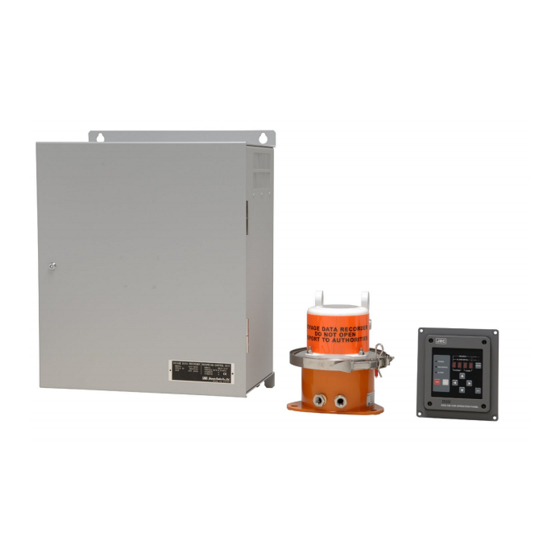
Page 10: Outlook Of System Components
Outlook of system components Recording Control Unit Protective capsule Unit Operation Panel Unit... -
Page 11: Table Of Contents
Contents Contents Preface ............................. i Precautions Before Operation .......................ii Outlook of System Components....................vi Abbreviations ..........................ix Glossary ............................x 1. Operation..........................1 Outline of the Equipment ....................1 Configuration........................1 1.2.1 System Diagram ......................3 Starting and Stopping the System ..................4 1.3.1 Starting the System ..................... - Page 12 Contents General Environmental Condition ................... 35 2.8.1 Location ........................35 2.8.2 Power supply environment ..................36 2.8.3 Environment....................... 36 3. Maintenance and Inspection ......................37 Daily Maintenance ......................37 3.1.1 Cleaning........................37 3.1.2 Check of the expiry date of the battery ..............37 Periodic Inspection ......................
-
Page 13: Abbreviations
Abbreviations Abbreviations S-VDR: Simplified-Voyage Data Recorder IMO: International Maritime Organization IEC: International Electrotechnical Commission PCU: Protective Capsule Unit RCU: Recording Control Unit CF CARD: Compact Flash Card FAN ABN. LED: Fan Abnormal LED FGB: Frame Grabber Board OPU: Operation Panel Unit PCMCIA: Personal Computer Memory Card International Association HDD:... -
Page 14: Glossary
Glossary Glossary MSC.163(78): IMO Performance Standard for S-VDR IEC61996-2: Performance Requirements for S-VDR IEC60945: General Requirements IEC61162: Digital Interfaces Standard HDT: Heading true sentence header ID of IEC61162-1 VBW: Dual ground/water speed sentence header ID of IEC61162-1 UXGA: Ultra eXtended Graphics Array (1600 x 1200: High resolution pixel) -
Page 15: Operation
1. Operation 1.1 Outline of the Equipment This equipment helps to detect the cause of marine accident to prevent the recurrence in the future. The equipment records voyage data, as required by the International Standard, during the navigation and the hull data of the vessel. 1.2 Configuration The standard configuration of the equipment is shown in Table 1. - Page 16 1. Operation The options configuration of the equipment is shown in Table 2. Table 2: Options Configuration Name of Optional Component Type Name Function To use an “Exposed” type, remove the flange of Microphone Unit NVT-161 “Built in the ceiling” one. Maximum nine sets of microphones can be installed, inclusive of standard configuration.
-
Page 17: System Diagram
1. Operation 1.2.1 System Diagram Figure 1 The system diagram of the equipment. Figure 1: System Diagram... -
Page 18: Starting And Stopping The System
1. Operation 1.3 Starting and Stopping the System 1.3.1 Starting the System ATTENTION To operate the Recording Control Unit, the front door has to be unlocked and opened. To turn on the equipment, after all units are connected, follow the procedure described below. 1. - Page 19 1. Operation 6. Checking the System Operation When the Recording Control Unit, the Operation Panel Unit, the Protective Capsule Unit, the Microphone Unit and the option unit are all on, and when they operate normally, LEDs on the Main Control Board, the Power Supply Unit in the Recording Control Unit and the Operation Panel Unit display as follows.
-
Page 20: Stopping The System
1. Operation 1.3.2 Stopping the System To stop the equipment, follow the procedures described below. ATTENTION To operate the Recording Control Unit, the front door has to be unlocked and opened. ATTENTION Do not turn off the breaker of the power distribution board while the system is active. -
Page 21: Operational Description
1. Operation 1.4 Operational Description In this section the basics of operation are explained. The operations can be performed on the Main Control Board of the Recording Control Unit. (To use the Recording Control Unit, the front door has to be unlocked and opened.) 1.4.1 To Stop Recording Data onto the Protective Capsule Unit Do not stop recording data into the Protective Capsule Unit unless any of the ATTENTION... -
Page 22: Actions To Be Taken At The Time Of An Accident (Guidelines)
6) After the copy has been finished, insert the CF CARD into the CARD slot on the Main Control Board. (Be sure that the JRC-label side is pointing right on the CF CARD.) 7) Make sure that the CARD LED lights up. -
Page 23: Stopping The Audible Alarm On The Operation Panel Unit
1. Operation Case 2: Carrying on the voyage is not possible as the accident is serious… Step Actions Operation of RCU Ref. Stop recording data onto the S-VDR Press the REC STOP SWITCH. Section when voyage is stopped by the accident. Make sure that the REC LED is 1.4.1 turned off. -
Page 24: Recording Control Unit (Ndv-1850)
1. Operation alarms are detected. 1.5 Recording Control Unit (NDV-1850) 1.5.1 Names of Parts of the Recording Control Unit (NDV-1850) 1) Keyhole Figure 2: The Recording Control Unit (The front door is closed) 2) Power Supply Unit 3) Data Processor Unit 4) I/F for connecting external signals (Connection ports are located herein.) 5) Battery... - Page 25 1. Operation Table 3: Names and Functions of the Recording Control Unit Names and Functions Keyhole: Used for opening and closing the front door. Power Supply Unit: Incorporated into the Recording Control Unit. It has an external battery and supplies power to the Protective Capsule Unit, the Operation Panel Unit and the Microphone Unit in case of a blackout.
-
Page 26: Power Supply Unit
1. Operation 1.5.2 Power Supply Unit 1.5.2.1 Names and functions of each part of the Power Supply Unit 1) POWER SWITCH 3) POWER LED 8) BATTERY VOLTAGE TEST TERMINAL 7) BLACKOUT 9) FAN TEST SWITCH 2) FUSE 4) BATTERY ABN. LED 5) BATTERY OP. - Page 27 1. Operation 1.5.2.2 How to operate the Power Supply Unit 1. Starting the power source: 1) Turn on the POWER SWITCH. 2) Then the POWER LED lights up. 2. Stopping the power source: 1) Before turning off the power source, press the CARD STOP SWITCH to stop the backup of CF CARD.
- Page 28 1. Operation 4. If the FAN ABN. LED lights up: Follow the procedures described in 3.3: Trouble Shooting. CAUTION If the FAN ABN. LED lights up, either of the two fans of the Power Supply Unit is out of order and needs to be replaced. Ignoring the caution may result in failures. Please contact the Sales Department, the nearest branch company, branch office, sales office, or any agent of Japan Radio Co., Ltd.
-
Page 29: Data Processor Unit
5) MEDIA LED 3) REC STOP SWITCH 6) CARD STOP SWITCH 10) HUB (VDR-LAN) 14) LAN CONNECTOR (VDR-LAN) 11) LAN CONNECTOR (JRC-LAN) (Option) MAIN CONTROL BOARD FRAME GRABBER BOARD (AUDIO RECORDING BOARD on MCB) Figure 5: The Data Processor Unit... - Page 30 1. Operation Table 6: Names and Functions of the Data Processor Unit Names and Functions REC LED (MCB): Lights up when the data are being successfully recorded into the Protective Capsule Unit. REC START SWITCH (MCB): Used to restart recording the data into the Protective Capsule Unit. REC STOP SWITCH (MCB): Used to stop recording the data into the Protective Capsule Unit.
- Page 31 6) After the copy has been finished, insert the CF CARD into the CARD slot on the Main Control Board. (Be sure that the CF CARD JRC-label side is pointing right.) 7) Make sure that the CARD LED lights up.
- Page 32 1. Operation 9) The old data which had been recorded over 13.5 hours previously in the CF CARD is erased. ATTENTION When the CARD LED is left turned off for 10 minutes or more, the MEDIA LED lights up on the Main Control Board and the Operation Panel Unit gives the alarm with ALARM BUZZER.
-
Page 33: Operation Panel Unit (Ncg-169)
1. Operation 1.6 Operation Panel Unit (NCG-169) 1.6.1 Names and functions of each part of the External Operation Board 7) HEADING LED 8) ALARM DETAIL LED HEADING ALARM DETAIL 1) POWER LED 9) MODE SWITCH POWER MODE 2) RECORDING LED 10) ERROR CODE LED RECORDING... - Page 34 1. Operation Names and Functions HEADING LED: Lights when the Operation Panel Unit is operated in NSK mode. The HEADING LED blinks when the initial value of heading is not registered. The NSK mode is usable when the NSK-I/F Board is activated. If the NSK-I/F Board is not activated, the HEADING LED is turned off all the time.
-
Page 35: How To Operate The Operation Panel Unit (Normal Mode)
1. Operation 1.6.2 How to operate the Operation Panel Unit (Normal mode) 1. If an error is detected: 1) The ALARM BUZZER sounds if an error is detected in the S-VDR. 2) The ALARM LED blinks. 3) The four digit ERROR CODE LEDs blink. 4) Press the ALARM ACK SWITCH until the buzzer stops. - Page 36 1. Operation 8) If the blackout is restored in less than 2 hours, the Recording Control Unit returns to normal operation automatically. 4. To adjust the brightness of LEDs: 1) Press the DIMMER SWITCH to adjust the brightness of the LEDs. 2) Press the switch again then the LEDs become darker.
- Page 37 1. Operation Table 8: ERROR code table of the Operation Panel Unit (2/3) ALARM DETAIL CONTENTS CATEGORY SYSYTEM CODE MCB Initialize error An abnormality has been detected in the Main Control Board. CF CARD alarm Ten minutes or more has passed since the CF CARD was taken out.
- Page 38 1. Operation Table 8: ERROR code table of the Operation Panel Unit (3/3) ALARM DETAIL CONTENTS CATEGORY SYSYTEM CODE CH1 Radar image data error The FGB does not receive RGB signals from Radar connected to CH1. CH2 Radar image data error The FGB does not receive RGB signals from Radar connected to CH2.
- Page 39 1. Operation Table 9: The conversion table of a code and equipment A connection channel is displayed when the equipment which is not defined by the following table is connected. The codes from 01 to 16 identify connection channel. ALARM DETAIL Equipment SYSYTEM CODE...
-
Page 40: How To Operate The Operation Panel Unit (On Nsk Mode)
1. Operation 1.6.3 How to operate the Operation Panel Unit (on NSK mode) The NSK mode is usable only when the NSK-I/F Board is activated. The board is needed to receive ship’s heading angle either in Synchro or in step mode or to input log speed in pulse. When the NSK-I/F Board is not activated, the Operation Panel Unit is not operated in NSK mode. -
Page 41: Specification
2. Specification 2.1 Protective Capsule Unit: PCU (NDH-317) (1) Function: The Protective Capsule Unit (PCU) is not a float-free type but a fixed type. The PCU records navigation data, hull data, conversation in the bridge, conversation over VHF radio, and radar image data to the recording medium in the PCU. When submerged, the Underwater Acoustic Beacon with PCU, which is battery-powered, transmits pulsed acoustic signal for capsule searchers. -
Page 42: Recording Control Unit: Rcu (Ndv-1850)
When radar images cannot be recorded, the output data of AIS must be recorded as a substitute. However, JCY-1850 can also record both AIS data and radar images. If the sensor outputs no data by IEC61162, items 5)-12) are not recorded. - Page 43 Radar image data input (input of No1. X band radar is recommended): 1) Input channel: 2 (channels) Auto selection of a radar image from both channels (If the radar is of JRC make, automatic selection of on-operation radar is possible.) 2) Input interface: analog RGB/Hs/Vs - RGB: 0.7Vp-p (video signal)
-
Page 44: Power Supply Unit: Psu
2. Specification 2.2.3 Power Supply Unit: PSU (1) Function: a) Power supply to RCU and PCU in normal operation b) Power supply to RCU and PCU for 2 hours on blackout. (2) Performance: a) Input voltage range: 100 - 120VAC +/- 10% 1-phase 50/60Hz +/-5% 200 - 240VAC +/- 10% 1-phase 50/60Hz +/-5% (Auto switching) b) Output voltage:... -
Page 45: Nsk Interface
(2) Performance: Radar switching recording function supports for connecting two non-JRC radars (refer to 2 and 3 below). However, for non-JRC radars, we do not recommend using switching recording function because automatic identification of the working radar is not functional under the normal operation conditions. - Page 46 2. Specification b) Switching SW connection Recording modes can be selected by connecting the switching SW of the following specification to the dry contact input (PI_1 and PI_2 of TB406) of Recording Control Unit (RCU). AUTO mode: Images of CH to which the synchronized signals are outputted are automatically selected and recorded.
-
Page 47: Operation Panel Unit: Opu (Ncg-169)
2. Specification 2.3 Operation Panel Unit: OPU (NCG-169) (1) Function: Visible indication and audible alarm for VDR system alarm in the Wheelhouse Display of the cause of an error Input of Heading initial value (2) Performance: a) Type: Flush mount type or Wall mount type b) Power supply: Supplied from the Recording Control Unit NDV-1850 c) Indication:... -
Page 48: Connection Box (Nqe-3163)
2. Specification 2.5 Connection Box (NQE-3163) (1) Function: Waterproofed type junction box which connects RCU with a PCU. (2) Performance: a) Connection device: Built-in terminal blocks (3) Environmental condition: a) Operating temperature: -25 deg. to +55 deg. (IEC 60945 exposed type) b) Temperature and humidity: +40°C, 93% 2Hz to 13.2Hz ±1.0mm... -
Page 49: General Environmental Condition
2. Specification (2) Performance: a) Basic performance: It is the same as the Radar image input specification of the Recording Control Unit. b) Communication port To the NDV-1850 RCU via Ethernet (3) Environmental condition: a) Operating temperature: -15 deg. to +55 deg. (IEC 60945 protected type) b) Temperature and humidity: +40°C, 93% c) Vibration:... -
Page 50: Power Supply Environment
2. Specification 2.8.2 Power supply environment a) AC power supply input range: 1) AC100/110/115/120V ±10% 2) AC200/220/240V ±10% b) AC power supply frequency fluctuation range: 1) 50Hz ±5% 2) 60Hz ±5% 2.8.3 Environment a) Exposed type equipment (Protective Capsule Unit, Waterproof Microphone Unit) 1) Operation temperature range: -25 °... -
Page 51: Maintenance And Inspection
3. Maintenance and Inspection WARNING Do not attempt checking or repairs on the internal part of the equipment by yourself. Checking or repairs by anyone other than our professional maintainer may result in a fire or an electric shock. Ask for checking or repairs of the inside of the equipment to the Sales Department, the nearest branch company, a branch office, a sales office, or any agent of Japan Radio Co., Ltd. -
Page 52: Periodic Inspection
3. Maintenance and Inspection 3.2 Periodic Inspection Yearly inspections are recommended on the inside of the equipment and on its connections with the Power Supply Unit and the other devices. For these inspections, you will be charged. Annual maintenance is requested by the Ship Class, please contact the Sales Department, the nearest branch company, a branch office, a sales office, or any agent of Japan Radio Co., Ltd. - Page 53 3. Maintenance and Inspection (2) Symptom Table for The Data Processor Unit (NDL-46) Symptom Causes Actions to be taken REC LED fails to The Recording Control Unit is off. Check the switchboard. light. The power is not supplied to the Turn on the Power Supply Unit.
-
Page 54: The Operation Panel Unit (Ncg-169)
3. Maintenance and Inspection 3.3.2 The Operation Panel Unit (NCG-169) All failures of the Recording Control Unit are indicated by the Operation Panel Unit as an error code. Symptom Causes Actions to be taken All LEDs blink and The software of the Recording Control Reboot the Recording Control Unit. - Page 55 3. Maintenance and Inspection Symptom Causes Actions to be taken Faulty wiring between the Recording Check the Connection Box. ERROR CODE: “20__” lights up. Control Unit and the Protective Capsule Unit Fault in the Recording Control Unit Reboot the Recording Control Unit, and see if the symptom persists.
- Page 56 3. Maintenance and Inspection Symptom Causes Actions to be taken Fault in the Audio Recording Board Reboot the Recording Control Unit, ERROR CODE: “40__”/“41__”/ and see if the symptom persists or not. If yes, contact us. “42__” lights up. Fault in RGB signals from a RADAR Check the RADAR.
-
Page 57: After-Sales Service
Trouble conditions (as detailed as possible. Refer to “S-VDR Failure Check List” in the next page) c) Name of shipping company/organization, address and telephone number For further details of after-sales service, contact the JRC Offices in the list at the end of this manual. - Page 58 4. After-sales service S-VDR Failure Check List When placing an order for repair of the product, you are kindly requested to check “Yes” “No” boxes on the list shown below and send the sheet back to our office. If there is any unclear items, contact the vessel on which the product is installed, and make the uncertainly clear.
-
Page 59: Disposal Of Unit
4. After-sales service Disposal of unit When disposing of this unit, abide the local laws and regulations. Contact the Sales Department, the nearest branch company, branch office, sales office, or any agent of Japan Radio Co., Ltd. and ask them to replace it without discarding the battery. - Page 60 4. After-sales service This page is intentionally left blank...
-
Page 61: Outline Drawings
5. Outline Drawings 5.1 Recording Control Unit: NDV-1850 The Outline Drawing of the Recording Control Unit... -
Page 62: Operation Panel Unit: Ncg-169
5. Outline Drawings 5.2 Operation Panel unit: NCG-169 NCG-169 VDR OPERATION PANEL The Outline Drawing of the Operation Panel Unit... -
Page 63: Protective Capsule Unit: Ndh-317
5. Outline Drawings 5.3 Protective Capsule Unit: NDH-317 VOYAGE DATA RECORDER TA RECORDER DO NOT OPEN T OPEN REPORT TO AUTHORITIES AUTHORITIES L 3 The Outline Drawing of the Protective Capsule Unit... -
Page 64: Connection Box: Nqe-3163
5. Outline Drawings Connection Box: NQE-3163 The Outline Drawing of the Connection Box... -
Page 65: Microphone Unit: Nvt-161
5. Outline Drawings 5.5 Microphone Unit: NVT-161 The Outline Drawing of the Microphone Unit... -
Page 66: Waterproof Microphone Unit: Nvt-162
5. Outline Drawings Waterproof Microphone Unit: NVT-162 Option The Outline Drawing of the Waterproof Microphone Unit... -
Page 67: Radar Interface Unit: Nwp-46
5. Outline Drawings Radar Interface Unit: NWP-46 Option The Outline Drawing of the Radar Interface Unit... - Page 68 5. Outline Drawings This page is intentionally left blank...
-
Page 69: Block Diagrams
6. Block Diagrams 6.1 Recording Control Unit NDV-1850 The Block Diagram of Recording Control Unit... -
Page 70: Operation Panel Unit Ncg-169
6. Block Diagrams Operation Panel Unit NCG-169 The Block Diagram of Operation Panel Unit... -
Page 71: Microphone Unit Nvt-161
6. Block Diagrams 6.3 Microphone Unit NVT-161 The Block Diagram of Microphone Unit... -
Page 72: Waterproof Microphone Unit Nvt-162
6. Block Diagrams 6.4 Waterproof Microphone Unit NVT-162 Option The Block Diagram of Waterproof Microphone Unit... -
Page 73: Radar Interface Unit Nwp-46
6. Block Diagrams Radar Interface Unit NWP-46 Option The Block Diagram of Radar Interface Unit...