Table of Contents
Advertisement
Advertisement
Table of Contents

Related Manuals for Simrad NAC-2


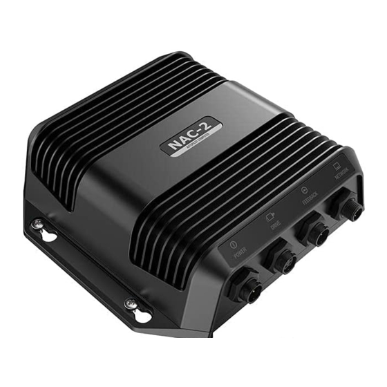
Summary of Contents for Simrad NAC-2
- Page 1 NAC-2/NAC-3 Commissioning Manual ENGLISH www.bandg.com | www.simrad-yachting.com...
- Page 3 Marine Electronics Association. Copyright Copyright © 2016 Navico Holding AS. Warranty The warranty card is supplied as a separate document. In case of any queries, refer to the product's web site on www.simrad-yachting.com or www.bandg.com. Preface | NAC-2/NAC-3 Commissioning Manual...
- Page 4 The requirements of level 2 devices of Radiocommunications (Electromagnetic Compatibility) standard The relevant Declaration of conformity is available in the product's section on www.simrad-yachting.com or www.bandg.com. About this manual The manual assumes that the user has basic knowledge of navigation, nautical terminology and practices.
-
Page 5: Table Of Contents
Contents Introduction NAC-2 and NAC-3 autopilot computers Autopilot controllers Autopilot computer setup 10 Dockside setup Data source selection Boat characteristics Drive configuration Rudder setup 16 Sea trial Compass setup Transition speed Set rudder zero position Set turn rate Tuning the autopilot... - Page 6 37 Dimensional drawings NAC-2 NAC-3 38 Supported data NMEA 2000 PGNs NMEA 0183 sentences NMEA 2000 PGN description Contents | NAC-2/NAC-3 Commissioning Manual...
-
Page 7: Introduction
NMEA 2000 devices. The NAC-2 is designed for boats up to 10 metres (33 feet) in length and is suitable for low-current pumps, mechanical drive units, or solenoid valves (8 amps continuous/16 amps peak). - Page 8 (default) values. A notification will be displayed, and a complete setup has to be made. Failure to do so correctly may prohibit the autopilot from functioning properly! Introduction | NAC-2/NAC-3 Commissioning Manual...
- Page 9 Drive Set turn rate low speed con guration Check rudder Tune steering feedback source parameters low selection speed Set turn rate high Rudder feedback speed calibration Tune steering Rudder test Operational autopilot system Introduction | NAC-2/NAC-3 Commissioning Manual...
-
Page 10: Dockside Setup
Used if no speed info is available. It is used by the autopilot system to calculate steering parameters. Drive configuration The drive configuration controls how the autopilot computer operates the steering system. Refer to your drive unit documentation for relevant specifications. Dockside setup | NAC-2/NAC-3 Commissioning Manual... -
Page 11: Drive Engage
Output activated when autopilot computer is in Auto, NoDrift or Navigation modes. For manual rudder control (Standby, NFU and FU) the output is not activated. Typically used to switch between two rudder speeds on a continuous running pump, used when Dockside setup | NAC-2/NAC-3 Commissioning Manual... -
Page 12: Minimum Rudder
A wide deadband will cause inaccurate steering. It is recommended to check rudder stability in AUTO mode at cruising speed to get pressure on the rudder. (Slight hunting observed dockside may disappear at cruising speed.) Dockside setup | NAC-2/NAC-3 Commissioning Manual... -
Page 13: Rudder Setup
Stand clear of the helm and do not attempt to take manual control of the rudder during this test! Rudder source The correct rudder source has to be selected before the rudder feedback calibration can be performed. Rudder source selection, MFDs Dockside setup | NAC-2/NAC-3 Commissioning Manual... -
Page 14: Rudder Feedback Calibration
• Run the rudder test as described in the on-screen instructions - Rudder should make a small movement within 10 seconds, then follow up with travelling both directions Dockside setup | NAC-2/NAC-3 Commissioning Manual... - Page 15 To perform the VRF calibration you must be able to view the movement of the rudder. • Follow the on-screen guided steps until the VRF calibration is completed. Dockside setup | NAC-2/NAC-3 Commissioning Manual...
-
Page 16: Sea Trial
The setup needs to be done from an appropriate display unit. Depending on the unit, access to the compass setup is available from the compass’s device dialog, or from a dedicated Calibration option in the unit’s Settings menu. Device dialog, MFDs Sea trial | NAC-2/NAC-3 Commissioning Manual... -
Page 17: Transition Speed
10 knots (= Transition speed plus 1 knot) • The system changes from High profile to Low profile when the speed decreases to 8 knots (= Transition speed minus 1 knot) Sea trial | NAC-2/NAC-3 Commissioning Manual... -
Page 18: Set Rudder Zero Position
The captured turn rate will be stored in the active steering profile. This setting must therefore be repeated for each steering profile. Tuning the autopilot Ú Note: Tuning of the autopilot must be done separately for low and high speed profiles. Sea trial | NAC-2/NAC-3 Commissioning Manual... - Page 19 Autotuning can be stopped at any time by pressing the STBY key on the autopilot controller. The autotuning takes approximately 3 minutes to complete. When completed the autopilot automatically switches to Standby mode, and the rudder must be controlled manually. Sea trial | NAC-2/NAC-3 Commissioning Manual...
-
Page 20: Manual Tuning
(well clear of the transition speed) to avoid profile switching during tuning. Then activate the Rudder gain option. Adjust the value according to the descriptions below. If required, adjust slightly the Counter rudder option. • Tuning parameters, MFDs Sea trial | NAC-2/NAC-3 Commissioning Manual... - Page 21 Counter rudder is the amount of counteracting (opposite) rudder applied to stop the turn at the end of a major course change. The settings depend on vessel’s characteristics, inertia, hull shape and rudder efficiency. Sea trial | NAC-2/NAC-3 Commissioning Manual...
- Page 22 (due to propeller rotation direction), do the course changes in both directions. You may end up with a compromise setting of Counter rudder that gives a little overshoot to one side and a bit creeping response to the other. Sea trial | NAC-2/NAC-3 Commissioning Manual...
-
Page 23: User Settings
Steering profile settings The NAC-2 and NAC-3 include two steering profiles (High and Low), used for high and low boat speed. The initial parameters are automatically assigned when you select your vessel type. -
Page 24: Sailing Parameters
If the course change is greater than this set limit, you are prompted to verify that the upcoming course change is acceptable. Sailing parameters Ú Note: Only available if the boat type is set to SAIL. User settings | NAC-2/NAC-3 Commissioning Manual... -
Page 25: Turn Pattern Settings
Sail. All turn patters, except the U-turn, have associated turn pattern settings. Depending on the autopilot controller these turn pattern settings can be adjusted before you start the turn or during the turn. User settings | NAC-2/NAC-3 Commissioning Manual... - Page 26 Steers the vessel in a circle. • Turn variable: - Rate of turn. Increasing the value makes the vessel turn a smaller circle. U-turn Changes the current set heading to be 180° in the opposite direction. User settings | NAC-2/NAC-3 Commissioning Manual...
- Page 27 - Leg distance Lazy-S turn Makes the vessel yaw around the main heading. • Turn variables: - Course change (C) - Turn radius (D) Depth contour tracking (DCT) Makes the autopilot follow a depth contour. User settings | NAC-2/NAC-3 Commissioning Manual...
- Page 28 AUTO mode. It is recommended to turn ON the AP Depth Data Missing alarm when using DCT. When this alarm is activated an alarm will be raised if the depth data is lost during DCT. User settings | NAC-2/NAC-3 Commissioning Manual...
-
Page 29: Installation Verification
"Drive configuration" on page 10 calibrated "Compass setup" on page 16 Compass calibrated Seatrial completed (manual or "Sea trial" on page 16 autotune) Boat specific settings Boat Settings Boat type Boat length Cruising speed Transition sped Installation verification | NAC-2/NAC-3 Commissioning Manual... - Page 30 Manual deadband Minimum output Maximum output Sailing parameters Settings Wind mode Tack time Tack angle Manual speed Steering profiles Settings Low Speed High Speed Turn Rate Rudder gain Counter rudder Autotrim Init rudder Rudder limit Installation verification | NAC-2/NAC-3 Commissioning Manual...
- Page 31 Course change confirm angle Turn Pattern settings Settings Continuous Rate of turn Spiral Initial radius Change/turn Zigzag Course change Leg distance Square Leg distance Lazy-S Course change Turn radius Depth contour Depth gain Installation verification | NAC-2/NAC-3 Commissioning Manual...
-
Page 32: Maintenance
You can check the autopilot computer's software version from the display unit's Device list. The latest software is available for download from the product website on www.simrad-yachting and www.bandg.com. Resetting the autopilot computer You can reset the autopilot to factory default settings. - Page 33 The first time the autopilot computer is started after reset, it will run through the automatic setup-procedure. Ú Note: Unless you need to clear all values set during the installation set-up procedure, you should not perform a reset of the autopilot computer. Maintenance | NAC-2/NAC-3 Commissioning Manual...
-
Page 34: Technical Specifications
Drive 12/24 V DC, min 10 mA, max 3 A Rudder Feedback Variable voltage/resistive 0‐5 V NMEA 2000 PGNs See "NMEA 2000 PGNs" on page 38 Physical Dimensions See "NAC-2" on page 37 Weight 0.6 kg (1.3 lbs) Compass Safe Distance 500 mm (20 inches) Warranty... -
Page 35: Nac-3
• On/off solenoid control of rudder. 12/24 V DC, common, load range 10 mA to 10 A, off current <1 mA Engage Output for bypass/clutch. 12/24 V DC, min 10 mA, max 3 A Technical specifications | NAC-2/NAC-3 Commissioning Manual... - Page 36 Alarm External alarm output for buzzer/relay. Max 100 mA, voltage level as local supply Physical Dimensions See "NAC-3" on page 37 Weight 0.7 kg (1.6 lbs) Compass Safe Distance 500 mm (20 inches) Warranty 2 years Technical specifications | NAC-2/NAC-3 Commissioning Manual...
-
Page 37: Dimensional Drawings
Dimensional drawings NAC-2 204.0 mm (8.1”) 57.0 mm (2.2”) 183.0 mm (7.2”) 169.0 mm (6.63”) NAC-3 211.0 mm (8.31”) 65.5 mm (2.58”) 195.0 mm (7.68”) Dimensional drawings | NAC-2/NAC-3 Commissioning Manual... -
Page 38: Supported Data
• MD: Main Device • RF: Rudder Feedback • VRF: Virtual Rudder Feedback 59392 59904 60160 60416 60928 65240 65305 65323 65341 65342 126208 126996 127237 127245 127250 127251 127257 127258 128259 128267 129025 Supported data | NAC-2/NAC-3 Commissioning Manual... - Page 39 129026 129029 129283 129284 130306 130577 130821 130840 130845 130846 130850 130851 130856 130860 Supported data | NAC-2/NAC-3 Commissioning Manual...
- Page 40 CD: Control Device TX RX TX RX TX RX TX RX TX RX 59392 59904 60160 60416 60928 65240 65305 65323 65341 65342 126208 126996 127237 127245 127250 127251 127257 127258 128259 128267 129025 129026 129029 Supported data | NAC-2/NAC-3 Commissioning Manual...
-
Page 41: Nmea 0183 Sentences
TX RX TX RX TX RX TX RX TX RX 129283 129284 130306 130577 130821 130840 130845 130846 130850 130851 130856 130860 NMEA 0183 sentences NMEA 2000 PGN 129284 130850 129283 129284 129285 129284 129284 128267 129025 129029 129025 129029 127250 Supported data | NAC-2/NAC-3 Commissioning Manual... -
Page 42: Nmea 2000 Pgn Description
** When true heading source. NMEA 2000 PGN description 59392 ISO Acknowledgement 59904 ISO Request 60160 ISO Transport protocol, Data transfer 60416 ISO Transport protocol, Connection management, RTS group function 60928 ISO Address claim 65240 ISO Commanded address Supported data | NAC-2/NAC-3 Commissioning Manual... - Page 43 129025 Position, Rapid update 129026 COG & SOG, Rapid update 129029 GNSS Position data 129283 Cross Track Error 129284 Navigation data 129283 Cross Track Error 129284 Navigation data 130306 Wind data 130577 Direction data Supported data | NAC-2/NAC-3 Commissioning Manual...
- Page 44 Supported data | NAC-2/NAC-3 Commissioning Manual...
- Page 45 Index Compatibility standard 4 About NAC-2 and NAC-3 7 Data source selection 10 User interface 7 Drawings Autopilot NAC-2 Dimensions 37 Autotuning 19 NAC-3 dimensions 37 Controllers 7 Drive Functions 7 Configuration 10 Manual tuning 20 Engage, Clutch, Auto 11...
- Page 46 Manual speed 25 connectors 32 Sailing parameters 24 Preventive Tack angle 25 maintenance 32 Tack time 25 Update Track approach angle 24 Software, NAC-2 and Turn patterns 25 NAC-3 32 Wind mode Auto Apparent True 25 Setup Compass, Device dialog,...