Table of Contents
Advertisement
Instruction Manual
D200126X012
Fisher
2502 Controllers
™
Contents
. . . . . . . . . . . . . . . . . . . . . . . . . . . . . . . . .
. . . . . . . . . . . . . . . . . . . . . . . . . . . . .
. . . . . . . . . . . . . . . . . . . . . . . . . . . . . . . . .
. . . . . . . . . . . . . . . . . . . . . . . . . . . . . . .
. . . . . . . . . . . . . . . . . . . . . . . . . . . . . . . . . .
. . . . . . . . . . . . . . . . . . . . . . . . . . . . . . . .
. . . . . . . . . . . . . . . . . . . . . . . . . . . . . . . . . .
. . . . . . . . . . . . . . . . . . . . . . . . . . . .
. . . . . . . . . . . . . . . . . . . . . . . . . . .
. . . . . . . . . . . . . . . . . . . . . . . . . . . . . . .
. . . . . . . . . . . . . . . . . . . . . . . . . . . . . . . . . .
. . . . . . . . . . . . . . . . . . . . . . . . .
. . . . . . . . . . . . . . . . . . . . . . . . .
. . . . . . . . . . . . . . . . . . . . . . . . .
. . . . . . . . . . . . . . . . . . . . . . . . . . . . . . . . . . . . .
. . . . . . . . . . . . . . . . . . . . . . . . . . . .
2502F Controller with Reset
. . . . . . . . . . . . . . . . . . . . . . . . . . . . . .
. . . . . . . . . . . . . . . . . . . . . . . . . . . . . . . .
. . . . . . . . . . . . . . . . . . . . . . . . . . . .
www.Fisher.com
. . . . . . . . . . . . . . . . . . . . . . . . .
. . . . . . . . . . . . . . . . . . . . . . . .
. . . . . . . . . . . . . . . . . . . . . .
. . . . . . . . . . . . . . . . . . . . .
. . . . . . . . . . . . . . . . . . .
. . . . . . . . . . . . . . . . . . . . .
. . . . . . . . . . . . . . . . . . . .
. . . . . . . . . . . . . . . . . . . .
. . . . . . . . . . . .
. . . . . . . . . . . . . . . . . . . . . . .
. . . . . . . . . . . . .
. . . . . . . . . . . . . . . . .
. . . . . . . . . . . . . . . . . . . . . . . .
. . . . . . . . . . . . . . . . . . . . . . .
. . . . . . . . . . . . . . . . . . . . . . . .
. . . . . . . . . . . . .
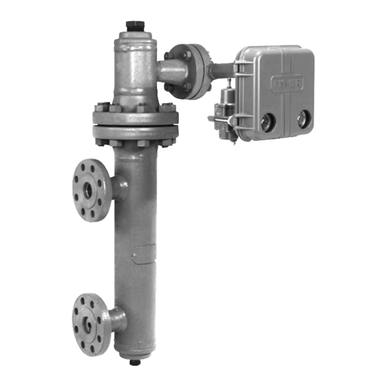
Figure 1. Fisher 2502 Controller Mounted on 249B
Sensor
2
2
2
2
2
4
5
5
6
6
7
9
9
10
11
12
13
13
13
14
15
15
15
15
W8334
15
16
16
17
18
19
21
21
22
23
. . . . . . . . . . . . . . . . . . . . . . . . . . . . . . . . . . .
24
. . . . . . . . . . . . . . . . . . . . . . . . . . . . . . . . . . .
2502 Controllers
2502 CONTROLLER
249B SENSOR
. . . . . . . . . . . . . . . . .
. . . . . . . . . . . . . . . .
. . . . . . . . . . . . . . . . . .
. . . . . . . . . . . . . . . . . . . . .
. . . . . . . . . . . . . . . . . . . . . . . . . . . . .
. . . . . . . . . . . . . . . . . . . . . . . . . .
. . . . . . . . . . . . . . . . . . . . . . . . . . .
. . . . . . . . . . . . . . . . . . . . . . . . . . . . . . .
June 2017
25
26
27
27
27
27
28
29
29
29
Advertisement
Table of Contents

Related Manuals for Emerson Fisher 2502


Summary of Contents for Emerson Fisher 2502
-
Page 1: Table Of Contents
2502 Controllers ™ Contents Figure 1. Fisher 2502 Controller Mounted on 249B Sensor Introduction ....... . . -
Page 2: Introduction
Introduction Scope of Manual This instruction manual provides installation, operating, calibration, and maintenance procedures for Fisher 2502 pneumatic controllers (figure 1) used in combination with Fisher 249 level sensors. This manual does not include regulator or sensor installation or maintenance procedures. For this information, refer to the instruction manual for the appropriate regulator and 249 level sensor. - Page 3 Instruction Manual 2502 Controllers D200126X012 June 2017 Table 1. Specifications Available Configurations Supply Pressure Requirement 1.4 bar (20 psig) for 0.2 to 1.0 bar (3 to 15 psig) 2502: A direct‐acting controller which provides output signal or 2.4 bar (35 psig) for 0.4 to 2.0 bar proportional‐plus‐reset control (6 to 30 psig) output signal 2502C: A 2502 with a level indicator assembly...
-
Page 4: Installation
Instruction Manual 2502 Controllers June 2017 D200126X012 Table 1. Specifications (continued) Hazardous Area Classification Declaration of SEP 2502 controllers comply with the requirements of Fisher Controls International LLC declares this ATEX Group II Category 2 Gas and Dust product to be in compliance with Article 4 paragraph 3 of the PED Directive 2014/68/EU. -
Page 5: 249 Sensors
Instruction Manual 2502 Controllers D200126X012 June 2017 WARNING Personal injury or property damage may result from fire or explosion if natural gas is used as the supply medium and preventive measures are not taken. Preventive measures may include, but are not limited to, one or more of the following: Remote venting of the unit, re‐evaluating the hazardous area classification, ensuring adequate ventilation, and the removal of any ignition sources. -
Page 6: Controller Orientation
Instruction Manual 2502 Controllers June 2017 D200126X012 Caged sensors will be shipped with the displacer installed in the cage. If the sensor is ordered with a tubular gauge glass, the gauge glass will be crated separately and must be installed at the site. Be certain that the cage equalizing connections are not plugged with foreign material. -
Page 7: Mounting Caged Sensors
Instruction Manual 2502 Controllers D200126X012 June 2017 Figure 4. Cage Head Mounting Positions RIGHT‐HAND MOUNTING LEFT‐HAND MOUNTING 67CFR FILTER/REGULATOR. AH9150-A A2613-2 Mounting Caged Sensor Note The cage must be installed plumb so that the displacer does not touch the cage wall. Should the displacer touch the cage wall, the unit will transmit an erroneous output signal. - Page 8 Instruction Manual 2502 Controllers June 2017 D200126X012 Figure 5. Cage Connection Styles STYLE 2: TOP STYLE 1: TOP STYLE 3: UPPER STYLE 4: UPPER AND LOWER SIDE AND BOTTOM AND LOWER SIDE SIDE AND BOTTOM SCREWED: S1 SCREWED: S2 SCREWED: S3 SCREWED: S4 FLANGED: F1 FLANGED: F2...
-
Page 9: Mounting Cageless Sensors
Instruction Manual 2502 Controllers D200126X012 June 2017 Mounting Cageless Sensor Note If a stillwell is used, it must be installed plumb so that the displacer does not touch the wall of the stillwell. Should the displacer touch the wall while the unit is in service, the unit will transmit an erroneous output signal. Since the displacer hangs inside the vessel, provide a stillwell around the displacer if the liquid is in a state of continuous agitation to avoid excessive turbulence around the displacer. -
Page 10: Top-Mounted Sensor
Instruction Manual 2502 Controllers June 2017 D200126X012 Figure 7. Cageless Sensor Mounting TOP MOUNTED SIDE MOUNTED W9517‐1 SIDE VIEW (SHOWING STILLWELL) CF5380‐A A3893 SIDE VIEW (WITHOUT STILLWELL) If an extension is used between the displacer spud and the displacer stem end piece, make sure the nuts are tight at each end of the displacer stem extension. -
Page 11: Supply Pressure
While use and regular maintenance of a filter that removes particles larger than 40 micrometers in diameter will suffice in most applications, check with an Emerson Automation Solutions field office and industry instrument air quality standards for use with corrosive gas or if you are unsure about the proper amount or method of air filtration or filter maintenance. -
Page 12: Prestartup Checks
Instruction Manual 2502 Controllers June 2017 D200126X012 Vent Assembly WARNING Personal injury or property damage could result from fire or explosion of accumulated gas, or from contact with hazardous gas, if a flammable or hazardous gas is used as the supply pressure medium. Because the instrument case and cover assembly do not form a gas‐tight seal when the assembly is enclosed, a remote vent line, adequate ventilation, and necessary safety measures should be used to prevent the accumulation of flammable or hazardous gas. -
Page 13: Adjustments
Instruction Manual 2502 Controllers D200126X012 June 2017 the sensor is to the right of the controller, remove the two mounting screws, turn the dial over so the arrow points to the right, then reinstall the mounting screws. On a controller with optional level indicator assembly the travel indicator plate is printed on both sides. If the sensor is to the left of the controller (right‐hand mounting), use the side of the plate that has the arrow pointing to the left. -
Page 14: Reset Adjustment
Instruction Manual 2502 Controllers June 2017 D200126X012 adjustment is performed by opening the controller cover and turning the percent proportional band knob (just below the RAISE LEVEL dial). Reset Adjustment To adjust reset action (figure 9) turn the knob clockwise to decrease reset time (the minutes per repeat). Turn the knob counterclockwise to increase the minutes per repeat. -
Page 15: Differential Relief Adjustment
Instruction Manual 2502 Controllers D200126X012 June 2017 Differential Relief Adjustment The differential relief valve protrudes from the back of the controller case on a construction with an F in the type number. Although normally factory‐set to relieve when the differential between the proportional and reset bellows reaches 5 psi, the differential may be reduced down to 2 psi by turning the adjustment screw clockwise or increased up to 7 psi by turning the screw counterclockwise. -
Page 16: Controller And Torque Tube Arm Disassembly
Determining Suspended Weight for Calibration CAUTION To avoid overloading a torque tube sized for interface or density applications under dry conditions, consult your Emerson sales office or Local Business Partner for the maximum allowable substitute weight W that can be used with your particular construction. -
Page 17: Calibration Procedure
Instruction Manual 2502 Controllers D200126X012 June 2017 = Weight of the displacer, in pounds (determine by weighing displacer). 0.0361 = Weight of one cubic inch of water (specific gravity = 1.0), in pounds. V = Volume of the displacer in cubic inches, that would be submerged at the level required by the calibration procedure. -
Page 18: Startup
Instruction Manual 2502 Controllers June 2017 D200126X012 1. Connect a supply pressure source to the controller and provide a supply pressure suitable for the sensing element range: 1.4 bar (20 psig) for a 0.2 to 1.0 bar (3 to 15 psig) output pressure range or 2.4 bar (35 psig) for a 0.4 to 2.0 bar (6 to 30 psig) output pressure range. -
Page 19: Principle Of Operation
Instruction Manual 2502 Controllers D200126X012 June 2017 4. Slowly open the downstream and upstream manual control valves in the pipeline and close the manual bypass valve if one is used. 5. With the controller set at the desired control point, narrow the proportional band until a cycling condition exists. Then broaden the proportional band slightly until stable control is obtained. - Page 20 Instruction Manual 2502 Controllers June 2017 D200126X012 Figure 10. Direct‐Acting Right‐Hand‐Mounted Fisher 2502‐249 Controller TORQUE TUBE SHAFT PROPORTIONAL BELLOWS FIXED MOVABLE PIVOT LEVEL SET PIVOTING ADJUSTMENT CROSS SPRINGS FIXED BEAM AND NOZZLE PIVOT FLAPPER RESET RESET BELLOWS VALVE PROPORTIONAL VALVE...
-
Page 21: 2502 Controller
Instruction Manual 2502 Controllers D200126X012 June 2017 The area ratio of the large diaphragm to the small diaphragm is 3 to 1. A 0.8 bar (12 psig) pressure change on the small diaphragm need only be balanced by a 0.3 bar (4 psig) change on the large diaphragm. A change in liquid level, interface level, or density changes the buoyant force exerted on the sensor displacer, which in turn imparts a rotary motion through the torque tube shaft. -
Page 22: Maintenance
Instruction Manual 2502 Controllers June 2017 D200126X012 Figure 11. Fisher 2502F Controller with Differential Relief Valve LEVEL SET MOVABLE PROPORTIONAL ADJUSTMENT BELLOWS RELIEF VALVE INNER CHAMBER DIFFERENTIAL FIXED RELIEF VALVE PIVOT BEAM AND PIVOTING DIAPHRAGM FLAPPER CROSS ASSEMBLY NOZZLE SPRINGS RESTRICTION RELIEF RESET... -
Page 23: Troubleshooting
The output signal measuring device should have a corresponding accuracy. Table 3 lists some common operating faults, their probable causes, and corrective action. Table 3. Troubleshooting Chart for Fisher 2502 Controllers Fault Possible Cause... -
Page 24: Removing Controller From Sensor
Instruction Manual 2502 Controllers June 2017 D200126X012 Table 4. Troubleshooting Chart for Fisher 2502 Controllers (continued) Fault Possible Cause Check Correction 2. Controller controlling off setpoint 2.1 Supply pressure not set 2.1 Make sure regulator supply 2.1 Reset the supply regulator or switching point. -
Page 25: Changing Mounting Method
Instruction Manual 2502 Controllers D200126X012 June 2017 CAUTION If the hex nut has not been loosened according to step 2, attempting to remove the controller from the sensor may bend the rotary shaft or operating arm and linkage. Be careful that the back of the controller case or the heat insulator does not drop down and bend the rotary shaft or shaft extension. -
Page 26: Installing Controller On Sensor
Instruction Manual 2502 Controllers June 2017 D200126X012 1. Remove the controller as described previously. 2. A controller is attached to the sensor in one or the other of the mounting positions shown in figure 4. Right hand mount is with the case to the right of the displacer when looking at the front of the case. Left hand mount is with the case to the left of the displacer. -
Page 27: Changing Proportional, Reset, Or Differential Relief Valve
Instruction Manual 2502 Controllers D200126X012 June 2017 5. Install and tighten the bearing assembly (key 12, figure 14) in the case (key 1, figure 14). Secure the operating arm base or pointer assembly to the rotary shaft by tightening the hex nut (key 40, figure 14). Connect the supply and output pressure tubing and perform the calibration procedure. -
Page 28: Reversing Action
Instruction Manual 2502 Controllers June 2017 D200126X012 4. Install each bellows by screwing it down over the stud (key 97, not shown) protruding from each end of the spacer. Secure with a bellows frame screw, and install the relay according to the Changing Relay section. 5. -
Page 29: Parts Ordering
Use only genuine Fisher replacement parts. Components that are not supplied by Emerson Automation Solutions should not, under any circumstances, be used in any Fisher instrument. Use of components not supplied by Emerson Automation Solutions may void your warranty, might adversely affect the performance of the instrument, and could cause personal injury and property damage. - Page 30 Instruction Manual 2502 Controllers D200126X012 June 2017 Description Description 44 Machine Screw, steel, pl (4 req'd) 9 Drive Pin, (2 req'd) 45 Machine Screw, stainless steel (2 req'd) 11 Relay Tubing, stainless steel 47 Spring (not shown), stainless steel 12* Ball Bearing Ass'y, brass, pl 49 Machine Screw, stainless steel (13 req'd) 13...
- Page 31 Instruction Manual 2502 Controllers D200126X012 June 2017 Figure 14. Fisher 2502 Controller Constructions 30A8942‐H TYPICAL CONTROLLER DETAIL OF RELIEF VALVE ASSEMBLY DETAIL OF LEVEL INDICATOR ASSEMBLY ON 2502F CONTROLLER ON 2502C CONTROLLER 30A8943‐H 43A2366‐H...
- Page 32 Responsibility for proper selection, use, and maintenance of any product remains solely with the purchaser and end user. Fisher is a mark owned by one of the companies in the Emerson Automation Solutions business unit of Emerson Electric Co. Emerson Automation Solutions, Emerson, and the Emerson logo are trademarks and service marks of Emerson Electric Co.