Samson 3730-2 Mounting And Operating Instructions
Series 3730
electropneumatic positioner
Hide thumbs
Also See for 3730-2:
- Mounting and operating instructions (176 pages) ,
- Quick manual (2 pages) ,
- Operating instructions manual (132 pages)

Related Manuals for Samson 3730-2


Summary of Contents for Samson 3730-2
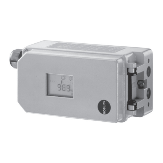
- Page 1 Series 3730 Electropneumatic Positioner Type 3730-2 Fig. 1 · Type 3730-2 Mounting and Operating Instructions EB 8384-2 EN Firmware version 1.4x Edition August 2007...
-
Page 2: Table Of Contents
Contents Page Contents Design and principle of operation ....8 Additional equipment......9 Technical data . - Page 3 Contents Initialization ......49 5.6.1 Initialization modes ......51 Fault/failure .
- Page 4 Safety instructions General safety instructions The positioner may only be assembled, started up or operated by trained and experienced personnel familiar with the product. According to these mounting and operating instructions, trained personnel refers to individuals who are able to judge the work they are assigned to and recognize possible dangers due to their specialized training, their knowledge and experience as well as their knowledge of the relevant standards.
- Page 5 Versions Type 3730-2 X X X X X 0 0 X 0 X 0 0 X 0 X X Article code Explosion protection Without II 2 G EEx ia IIC T6/II 2 D IP 65 T 80 °C acc. to ATEX...
- Page 6 Firmware modifications Modifications of positioner firmware in comparison to previous versions Previous 1.01 1.10 Via the serial interface and the serial interface adapter, the positioner can be configured and operated using TROVIS-VIEW software. The following additional status alarms were implemented: Code 76 - No emergency mode Code 77 - Program loading error Displays number of zero calibrations performed since the last initialization.
- Page 7 These Mounting and Operating Instructions EB 8384-2 EN are valid for positioners with firm- ware versions 1.40 to 1.49. The latest edition of these instructions, detailing the firmware version and modifications com- pared to the previous version, are available on the Internet at http://www.samson.de. EB 8384-2 EN...
-
Page 8: Design And Principle Of Operation
The positioner basically consists of a travel The positioner is equipped with an interface sensor system that functions proportional to to allow the SAMSON TROVIS-VIEW Con- the resistance, an analog i/p module with figuration and Operator Interface software downstream booster as well as the electronic to transmit data and parameters over an unit with a microcontroller. -
Page 9: Additional Equipment
Design and principle of operation Refer to Data Sheet T 8388 EN for more de- Version with solenoid valve tails on EXPERT valve diagnostics. Instruc- If the operating voltage for the solenoid tions on how to operate the software can be valve (12) fails, the supply pressure for the found in Mounting and Operating Instruc- i/p module is vented to the atmosphere. - Page 10 Design and principle of operation Since this signal is issued independent of the positioner’s input signal (min. current 3.8 mA), the actual travel/angle of rotation is controlled in real-time. Additionally, the position transmitter provides the possibility of signaling a positioner fault over a signal current of <2.4 mA or >21.6 mA.
-
Page 11: Technical Data
Design and principle of operation Technical data Type 3730-2 Positioner Travel, adjustable Direct attachment to Type 3277 Actuator: 3.6 to 30 mm Attachment according to IEC 60534-6-1: 3.6 to 200 mm Rotary actuators: 24° to 100° opening angle Travel range Adjustable within the initialized travel/opening angle ·... - Page 12 FM/CSA Intrinsically safe Class I, II, III, Division 1, Group A, B, C, D, E, F, G, T6 FM/CSA Non incendive Class I, Division 2, Group A, B, C, D, T6 Communication (local) SAMSON SSP interface and serial interface adapter Software requirements (SSP) TROVIS-VIEW with database module 3730-2...
- Page 13 Design and principle of operation Optional accessories for Type 3730-2 Positioner Solenoid valve ⋅ Approval according to IEC 61508/SIL Input 24 V DC · Reverse-polarity protection · Static destruction limit 40 V − 56 Power consumption I = (corresponds to 4.5 mA at 24 V) Ω...
-
Page 14: Attachment To The Control Valve - Mounting Parts And Accessories
– mounting parts and accessories The positioner can be attached either di- rectly to a SAMSON Type 3277 Actuator or according to IEC 60534-6 (NAMUR) to con- trol valves with cast yokes or rod-type yokes as well as to rotary actuators according to VDI/VDE 3845. - Page 15 Max. position 3277-5 25.0 3277 120/240/350 35.4 Actuators 10.0 50.0 Travel table for attachment according to IEC 60534-6 (NAMUR) SAMSON valves Non-SAMSON valves/actuators Associated pin Required lever cm² Rated travel Min. travel Max. position 60 and 120 with 17.7 Type 3510 Valve 25.0...
- Page 16 Lever For actuators Order no. Type 3271-5 with 60/120 cm² on Type 3510 Micro Valve (see Fig. 7) 1400-7457 Non-SAMSON and Type 3271 Actuators with 120 to 700 cm² 5 to 50 Without 1400-7454 Lever M mounted to basic unit...
- Page 17 VDI/VDE 3845 for all dimensions of fixing level 2, heavy version 1400-9244 parts Mounting parts for rotary actuators VDI/VDE 3845 (level 1), heavy-duty version 1400-9526 SAMSON Type 3278 160 cm² / VETEC Type S160 and Type R, heavy-duty version 1400-9245 AIR TORQUE 10 000, heavy-duty version 1400-9542 Connecting plate G ¼: 1400-7461 ·...
-
Page 18: Direct Attachment
Attachment to the control valve – mounting parts and accessories Direct attachment 4. Mount cover plate (10) with narrow side of the cut-out opening (Fig. xx, on the 2.1.1 Type 3277-5 Actuator left) pointing towards the signal pressure connection. Make sure that the bonded For the required mounting parts and acces- gasket (14) points towards the actuator sories with their order numbers, refer to Ta-... - Page 19 Attachment to the control valve – mounting parts and accessories Lever Symbols 1.1 Nut Switchover plate (9) 1.2 Disk spring Actuator stem Follower pin extends Follower clamp Screw plug Attachment left Attachment right Stopper Connecting plate Actuator stem 6.1 Seal rings retracts Pressure gauge bracket Signal pressure...
-
Page 20: Type 3277 Actuator
Attachment to the control valve – mounting parts and accessories 2.1.2 Type 3277 Actuator of the follower clamp (3). Adjust the le- ver (1) correspondingly and open the For the required mounting parts and acces- positioner cover to hold the positioner sories with their order numbers, refer to Ta- shaft in position at the cap or the switch ble 2 on page 16. - Page 21 Attachment to the control valve – mounting parts and accessories Lever Connection block 1.1 Nut 12.1 Screw 1.2 Disk spring 12.2 Stopper or connection for external piping Follower pin Switch plate Follower clamp Gasket Cover plate Formed seal Cover Gasket Lever M Cut-out of cover plate (10)
-
Page 22: Attachment According To Iec 60534-6
Attachment to the control valve – mounting parts and accessories Attachment according to sure both seal rings (6.1) are seated properly. IEC 60534-6 4. Select required lever size (1) M, L or XL The positioner is attached to the control valve and pin position according to the actua- using a NAMUR bracket (10). - Page 23 Attachment to the control valve – mounting parts and accessories Attachment to rod-type yokes, rod Ø 20 to 35 mm Attachment to NAMUR rib Additional bracket for 2800 cm² actuators with travel ≥ 60 mm Levers XL and L Lever 1.1 Nut 1.2 Disk spring Follower pin...
-
Page 24: Attachment To Type 3510 Micro-Flow Valve
Attachment to the control valve – mounting parts and accessories Attachment to Type 3510 Mi- cro-flow Valve The positioner is attached to the valve yoke using a bracket. For the required mounting parts and acces- sories with their order numbers, refer to Ta- ble 3 on page 16. - Page 25 Attachment to the control valve – mounting parts and accessories Lever Disk spring Follower pin Clamp Connecting plate Seal rings Pressure gauge bracket Pressure gauge mounting kit Bracket Note! Always use the connecting plate (6) included in the accessories to connect supply and output.
-
Page 26: Attachment To Rotary Actuators
Before attaching the positioner to the bore for pin position 90°. SAMSON Type 3278 Rotary Actuator, you 7. Place positioner on the top pair of have to mount the associated adapter (5) to the free end of the rotary actuator shaft. - Page 27 Attachment to the control valve – mounting parts and accessories Note! Always use the connect- ing plate (6) included in the accessories to con- nect supply and output. Never screw threaded Control valve opens counterclockwise parts directly into the housing. Slot Legend Figs.
-
Page 28: Reversing Amplifier For Double-Acting Actuators
Attachment to the control valve – mounting parts and accessories Reversing amplifier for dou- Note! ble-acting actuators Do not unscrew the sealing plug (1.5) from the reversing amplifier of the Type 3730 For use with double-acting actuators, the Positioner! positioner must be fitted with a reversing The rubber seal (1.4) is not required and amplifier. - Page 29 Attachment to the control valve – mounting parts and accessories From the positioner Control signals to the actuator Reversing amplifier Connecting plate 1.1 Special screws 6.1 O-rings 1.2 Gasket 6.2 Screws 1.3 Special nuts 1.4 Rubber seal 1.5 Sealing plug 1.6 Filter Fig.
-
Page 30: Attaching An External Position Sensor
Attachment to the control valve – mounting parts and accessories Attaching an external posi- tion sensor For mounting parts and accessories required for the external position sensor, refer to Ta- ble 6 on page 35. For accessories required for pneumatic connection to the positioner housing, refer to Table 7. - Page 31 Attachment to the control valve – mounting parts and accessories Type 3277 Actuator with 240 to 700 cm² 2. Screw the position sensor (20) onto the mounting plate (21). The signal pressure is routed to the connec- 3. Depending on the actuator size and rated tion at the side of the actuator yoke for ver- travel of the valve, determine the required sion "Actuator stem extends".
-
Page 32: Mounting The Position Sensor With Attachment According To Iec 60534-6
Attachment to the control valve – mounting parts and accessories 2.6.2 Mounting the position sensor Place the lever (1) in mid-position and hold it in place. Screw on the nut (1.1). with attachment according to 5. Place the follower clamp (3) on the actu- IEC 60534-6 ator stem, align and fasten it, making For the required mounting parts and acces-... -
Page 33: Mounting The Position Sensor To Type 3510 Micro-Flow Valve
Attachment to the control valve – mounting parts and accessories For other actuator sizes or travels, select the Place the lever (1) in mid-position and lever and pin position from the travel table hold it in place. Screw on the nut (1.1). on page 15. -
Page 34: Mounting The Position Sensor To Rotary Actuators
Attachment to the control valve – mounting parts and accessories 2.6.4 Mounting the position sensor 4. Place the lever (1) and disk spring (1.2) on the sensor shaft. to rotary actuators Place the lever (1) in mid-position and For the required mounting parts and acces- hold it in place. - Page 35 Version with CrNiMo steel bracket, see Fig. 15 Attachment to rotary actuators VDI/VDE 3845 for all dimensions of fixing level 2, heavy version 1400-9384 SAMSON Type 3278 160 cm²/VETEC Type S160 and Type R, 1400-9385 heavy version Positioner accessories Order no.
-
Page 36: Attaching Positioners With Stainless Steel Housings
Attachment to the control valve – mounting parts and accessories Attaching positioners with Air purging function for sin- stainless steel housings gle-acting actuators Positioners with stainless steel housings re- The exhaust air from the positioner can be quire mounting parts that are completely used to provide corrosion protection for the made of stainless steel or free of aluminum. -
Page 37: Connections
Connections If other valve accessories that vent the actua- Connections tor (e.g. solenoid valve, volume booster, quick exhaust valve) are used, this exhaust Pneumatic connections air must also be included in the purging function. The connection over the adapter at Caution! the positioner must be protected with a The threads in the positioner housing are not... -
Page 38: Signal Pressure Gauges
Connections 3.1.1 Signal pressure gauges d = Seat diameter [cm] Δp = Differential pressure across the To monitor the supply air (supply) and sig- valve [bar] nal pressure (output), we recommend to at- A = Actuator diaphgragm area [cm²] tach pressure gauges (see accessories in Ta- = Upper bench range value of the ac- bles 1 to 4). -
Page 39: Electrical Connections
Connections Electrical connections Caution! The terminal assignment specified in the cer- For electrical installation, you are re- tificate must be adhered to! Switching the quired to observe the relevant assignment of the electrical terminals may electrotechnical regulations and the cause the explosion protection to become in- accident prevention regulations that effective! Do not loosen enameled screws in apply in the country of use. - Page 40 Connections Note! The minimum permissible reference Caution! variable must not fall below 3.8 mA to oper- The erroneous connection of a voltage ate the positioner. source of only around 7 V (or around 2 V Accessories: when connected to the wrong pole) can al- Plastic cable gland, M20 x 1.5: ready damage the positioner.
-
Page 41: Switching Amplifiers
Connections 3.2.1 Switching amplifiers For operation of the limit switches, switching amplifiers must be connected in the output circuit. To ensure the operating reliability of the positioner, the amplifiers should comply with the limit values for output circuits ac- cording to EN 60947-5-6. If the positioner is to be installed in hazard- ous areas, the relevant regulations must be observed. -
Page 42: Operation
Operation switch position and re-initialize the Operation positioner. The switch position is prompted prior to an Note! initialization. After an initialization has been A summary about operation and start-up completed, changing the switch position can be found in section 8 on page 66. A does not have any effect on the operation of leaflet including the same summary is also the positioner. - Page 43 Operation Displays and their meaning AUtO Automatic mode Maximum range tEStinG Test function active Clockwise Not available Initialization in progress TunE Counterclockwise Rated travel Available Error Zero calibration ää Escape Increasing/increasing äæ ix greater than 21.6 mA OVERLOAD w > 22 mA Increasing/decreasing ix smaller than 2.4 mA Reset...
-
Page 44: Enabling And Selecting Parameters
Operation Enabling and selecting pa- Note! rameters To cancel a value that you have just entered under a code, turn the button until ESC The codes marked with an asterisk (*) in sec- appears on the display and press to con- tion 12 from page 71 onwards must be en- firm. -
Page 45: Operating Modes
Operation Operating modes Switching to manual operating mode Over Code 0 , press the button, AUtO 4.3.1 Automatic and manual oper- appears in the display, Code 0 blinks. ating modes Turn the button until MAN appears. Before initialization If the positioner has not been initialized yet, the automatic operating AUtO cannot be se- lected. -
Page 46: Safe - Fail-Safe Position
Start-up and settings 4.3.2 SAFE – fail-safe position Start-up and settings If you want to move the valve to fail-safe po- Note! sition, proceed as follows: A summary about operation and start-up can be found in section 8 on page 66. A leaflet including the same summary is also Select Code 0 , press the button. -
Page 47: Setting Volume Restriction Q
The position of volume restriction Q also de- pends on how the signal pressure is routed at the actuator in SAMSON actuators: Turn the button until Code 2 appears, and press the button to confirm. -
Page 48: Limiting The Signal Pressure
Start-up and settings Turn the button until the display is ad- 3. Turn the button until Code 1 appears. justed to the desired direction, then confirm Confirm Code 1 by pressing the but- reading direction by pressing the button. ton. The hand symbol and Code 1 blink. 4. -
Page 49: Initialization
Start-up and settings Simplified start-up For most applications, the positioner with its default settings is ready for operation, provided it has been properly attached. After the fail-safe position and the volume restriction have been set, the positioner only needs to be initialized by pressing the INIT key. Caution! Prior to starting the initialization procedure, check the maximum permissible supply pressure of the control valve to prevent the valve from being damaged. - Page 50 Start-up and settings The time required for an initialization pro- After a successful initialization, the cess depends on the transit time of the actu- positioner starts control operation indicated ator and may take several minutes. by the symbol. Positioners with EXPERT diagnostic func- The control position in % predetermined by the tions start plotting the reference graphs after...
-
Page 51: Initialization Modes
Start-up and settings An unsuccessful plotting of the reference After enabling configuration: graphs is indicated on the display by Code 81 (see error code list). After the initialization has been successfully Default MAX completed, the positioner still works prop- erly, even though the reference graph plot- ting has not been completed successfully. - Page 52 Start-up and settings If you want the display to indicate mm/°, Note! proceed as follows after configuration has The maximum possible travel must always been enabled: be greater than the nominal travel entered. → Code 4 , press Turn If this is not the case, the initialization is canceled (error indication Code 52) be- →...
- Page 53 Start-up and settings Enable configuration: Default MAX Default OFF → Code 6 , press Turn → NOM , press → Code 3 , press Turn Turn → ON , press Press INIT key to start initialization. Turn After enabling configuration: The initialization procedure may →...
- Page 54 Start-up and settings that the plant continues to operate with this valve position. The spare positioner should not be initial- ized. If necessary, reset the spare positioner using Code 36 . After the old positioner has been replaced Turn until the valve reaches its OPEN po- with a new one, the following parameters sition.
- Page 55 Start-up and settings Enable configuration: Default ää Default OFF → Code 7 , press Turn → Retain direction of action ää or → Code 3 , press Turn Turn select äæ. Press → ON , press Turn After enabling configuration: Default 100.0 Default OFF →...
- Page 56 EB 8384-2 EN...
- Page 57 Start-up and settings The positioner switches to automatic opera- tion. The current valve position is indicated in %. Note! If the positioner shows a tendency to oscil- late in automatic operating mode, the pa- rameters K and T must be slightly cor- rected.
-
Page 58: Fault/Failure
Start-up and settings Fault/failure Display indicating an error All status and fault alarms are assigned a code classified status in the positioner. To provide a better overview, the classified alarms are summarized in a condensed sta- After an error code has occurred, first try to tus for the positioner (see section 6). -
Page 59: Zero Calibration
Start-up and settings Zero calibration The valve briefly moves from the cur- rent travel/angle of rotation position In case of discrepancies with the closing po- to closed position. sition of the valve, e.g. with soft-sealed plugs, it may become necessary to recalibrate the zero point. -
Page 60: Start-Up Using Local Interface (Ssp)
Status and diagnostic alarms 5.10 Start-up using local inter- Status and diagnostic alarms face (SSP) The Type 3730-2 Positioner contains inte- grated diagnostics to generate classified sta- The positioner must be supplied with at least tus and diagnostic alarms. 4 mA. -
Page 61: Extended Expert
Status and diagnostic alarms For positioners with firmware version 1.30 Extended EXPERT or higher, EXPERT can be activated subse- diagnostics quently. To do so, order an activation code, specifying the positioner's serial number. In addition to the standard EXPERT diagnos- tic features, the optional EXPERT extended Classification of status... - Page 62 Status and diagnostic alarms Classification process in the positioner Status modification An alarm is assigned to one of following The classification of the status alarms can be classified states in the table: changed as required. They can be modified using TROVIS-VIEW Condensed status software over the local SSP interface.
- Page 63 Status and diagnostic alarms Logging and displaying diagnostic func- tions/alarms The last 30 alarms are logged in the positioner. However, it is important to note that the same alarm is only logged once when it first occurs. The alarms and the condensed states ap- pear on the display as described in the code list (section 12).
-
Page 64: Adjusting The Limit Switch
+41/–42. valve positions. The device is set up accordingly when deliv- ered ex works SAMSON. The desired switching function, i.e. whether the output relay shall be picked up or re- leased when the tag has entered the field,... - Page 65 Adjusting the limit switch Setting the switching point: For OPEN position: 1. Initialize positioner. Note! 2. Use the MAN function to move the During adjustment or testing, the switching positioner to 95 % (see LCD). point must always be approached from 3.
-
Page 66: Quick Start-Up Guide
Mounting Make sure the lever can still move. Direct attachment Attachment to rotary actuators to SAMSON Type 3277 Actuator Lever M pin position 90° Travel [mm] Actuator [cm²] Pin position Move the valve to CLOSED position, de- termine the opening direction. -
Page 67: Start-Up
Quick start-up guide Start-up Operation Selecting the parameters or values Connect pneumatic supply air (1.4 to Each parameter has a code number which 6 bar). is shown in the display. Apply an electrical reference variable (4 to Use the button to select. 20 mA). -
Page 68: Initialization
Quick start-up guide → Code 5 . ↵ turn Initialization Enter rated travel/angle. ↵ Note! → Code 6 , ↵ Turn Perform a reset (Code 36) before each ini- select NOM . ↵ tialization. Press INIT key. → Code 3 , ↵ Turn 8.3.3 Manual method (MAN) →... -
Page 69: Upgrading Options
Upgrading options Upgrading options Retrofitting an inductive limit switch Required retrofit kit: Limit switch order no. 1400-7460 Note! When working on explosion-protected devices, make sure the requirements specified in section 11 are complied with. 1. Take off the rotary pushbutton (3) and cap (1), unthread the five fixing screws (2) and lift off the plastic cover (9). -
Page 70: Activating The Optional Expert
Maintenance Activating the optional Servicing explosion-protected EXPERT diagnostics devices The optional extended EXPERT diagnostics If a part of the positioner on which the ex- can be activated subsequently. plosion protection is based needs to be ser- viced, the positioner must not be put back The required activation code is order num- into operation until an expert has inspected ber 1400-9318. -
Page 71: Code List
Code list Code list Parameter – Display, values Code Description [default setting] Note! Codes marked with an asterisk (*) must be enabled with Code 3 prior to configuration. Operating mode AUtO = Automatic mode MAN = Manual mode SAFE = Fail-safe position ESC = Escape [MAN] AUtO... - Page 72 Code list Nominal range For initialization using NOM or SUb, the nominal travel/angle of rotation of the valve must be entered. [15.0] mm or angle ° The permissible adjustment range depends on the pin position according to the table for Code 4. After initialization has been successfully completed, the maximum nominal travel/angle reached on initialization is displayed.
- Page 73 Code list Upper x-range value Upper range travel/angle of rotation in the nominal or operating range. Value is displayed or must be entered. 20.0 to 100.0 [100.0] % The characteristic is adapted. nominal range, Example: The operating range is modified, for example, to limit Specified in mm or angle °, provided the range of a control valve which has been sized too large.
- Page 74 Code list Final position w < If w approaches up to 1 % towards the final value that causes the valve to close, the actuator is immediately completely vented 0.0 to [1.0] % (with AIR TO OPEN) or filled with air (with AIR TO CLOSE). of the span adjusted via This action always lead to maximum tight-closing of the valve.
- Page 75 7: Segmented ball valve linear 3: Butterfly valve linear 8: Segmented ball valve eq. p. 4: Butterfly valve eq. percentage 9: User-defined * * Definition over SAMSON TROVIS-VIEW software w-ramp Open The time required to pass through the operating range when the valve opens.
- Page 76 Code list Alarm mode Switching mode of software limit switches alarm A1 and A2 in responding state (when positioner initialized). 0 to 3 [2] 1) Explosion-protected version according to EN 60947-5-6 0: A1 ≥ 2.1 mA A2 ≤ 1.2 mA 1: A1 ≤...
- Page 77 Code list Position transmitter x/ix Operating direction of the position transmitter; indicates how the travel/angle position is assigned to the output signal i, based on [ää] CLOSED position. äæ The operating range (see Code 8) of the valve is represented by the 4 to 20 mA signal.
- Page 78 Code list Blocking position Entering the blocking position. Distance up to CLOSED position. [0] mm/° /% Only necessary in initialization mode SUb. Reset Resets all start-up parameters to default (factory setting). Note: After setting RUN, the positioner must be re-initialized. [OFF] Display only, Position transmitter...
- Page 79 Code list Solenoid valve info Display only, indicates whether a solenoid valve is installed. If voltage is applied to the terminals of the integrated solenoid valve, YES and HIGH appear in alternating sequence. When there is no voltage applied (actuator vented, fail-safe posi- tion indicated by S symbol on display) YES and LOW appear in alternating sequence.
- Page 80 Code list Error codes – Remedy Condensed status alarm active, when prompted, Err appears. Initialization error (indicated on the display by the condensed status with the corresponding classification) x < range The value supplied by the measuring signal is either too high or too low, the measuring sensor is close to its mechanical limit.
- Page 81 Code list Init – Solenoid valve 1) A solenoid valve is installed (Code 45 = YES) and was not or not properly connected so that an actuator pressure could not be built up. The message appears when you attempt to initialize the positioner. 2) If you attempt to initialize the device from the fail-safe position (SAFE).
- Page 82 Remedy Return the positioner to SAMSON AG for repair. w too small The reference variable is much smaller than 4 mA (0 %); occurs if the power source that drives the positioner does not comply with the standard.
- Page 83 Remedy Confirm error and return to the automatic operating mode, or perform a reset and re-initialize the device. If this is not successful, return device to SAMSON AG for repair. Data memory The writing of data to the data memory does not work anymore, e.g.
- Page 84 Remedy Confirm error, perform reset and re-initialize the positioner. Internal device error 1 Internal device error Remedy Return the positioner to SAMSON AG for repair. Parameter info Error in the parameter info which is not critical for the control. Remedy Confirm error.
- Page 85 Code list Diagnostic parameters Error which is not critical for control. Remedy Confirm error. Check and, if necessary, start new reference run. Reference graphs Error on plotting the reference graphs of drive signal y steady-state or drive signal y hysteresis. •...
-
Page 86: Setup With Trovis-View Software - Parameter List
Internet link to SAMSON’s activation server where a unique activation code will then be generated and displayed. Enter this activation code into TROVIS-VIEW’s Activation dialog box. The soft- ware is now ready for use without any restrictions in the purchased scope. -
Page 87: Starting Trovis-View And Performing Basic Settings
Setup with TROVIS-VIEW software – parameter list 13.2 Starting TROVIS-VIEW and performing basic settings Settings may be entered into the TROVIS-VIEW operator interface when either the positioner is connected or not connected. When the positioner is connected, the data uploaded from the positioner can be overwritten. - Page 88 Setup with TROVIS-VIEW software – parameter list 1. Start TROVIS-VIEW. Make required settings in the View menu by activating or deactivating functions. When the Trend Viewer is activated, all operating data are uploaded cyclically from the positioner in online mode and shown in the form of graphs. Right-click on the graph to edit the graph format or to copy the logged data to a file.
- Page 89 Setup with TROVIS-VIEW software – parameter list 3. Select communication from the Options menu > Communication . 4. Click on Port settings and select port as well as server settings. 5. Select Convert in the File menu to select the firmware version of the positioner. It must match the version specified in the bar at the top.
-
Page 90: Setting Parameters
Setup with TROVIS-VIEW software – parameter list 13.3 Setting parameters Click on one of the folders listed in the left column to open a window listing the settings of the corresponding parameters. Place the mouse arrow on the parameter name to open a tool tip providing information about that particular parameter. -
Page 91: Parameter List
Freely available text fields Message Text field 1 to 5 Positioner serial Serial number of the positioner number Positioner product 3730-2 xxx Manufacturer model number of the positioner number Firmware version x.xx Current firmware version of device, Code 43 Diagnosis level... - Page 92 Setup with TROVIS-VIEW software – parameter list Identification – Positioner Device type 3730-2 Indicates exact model designation Identification – Positioner – Actuator Type identification Manufacturer ID number of the actuator that the actuator positioner is mounted upon Actuator type Single-acting...
- Page 93 Setup with TROVIS-VIEW software – parameter list Parameter Values Default Description Flow characteristic Linear 30:1/ Linear 50:1 Valve characteristic: Flow to valve travel Eq. perc. 30:1/ Linear 50:1/ Eq. perc. 50:1/ Other Valve dimensions DIN/ANSI Valve dimensions according to DIN or ANSI standard Nominal size DN 8...2100...
- Page 94 Setup with TROVIS-VIEW software – parameter list Status Condensed state Summarized state of the positioner. The condensed status is made up from the var- ious states. The condensed status can take on the following states: No alarm Maintenance required Maintenance demanded Maintenance alarm Function check The condensed states “Maintenance required”...
- Page 95 Setup with TROVIS-VIEW software – parameter list Parameter Value Default Description Positioner – Reference variable Direction of action Increasing/ Increasing/ Code 7 increasing >> increasing >> Incr./decr. <> Lower reference 0.0...75.0 % 0.0 % Code 12 range value Upper reference 25.0...100.0 % 100.0 % Code 13...
- Page 96 Setup with TROVIS-VIEW software – parameter list Positioner – Characteristic Linear Code 20 Characteristic Linear selection Equal percentage Eq. perc. reverse SAMSON butterfly valves linear eq. perc. VETEC rotary plug valves linear eq. perc. Segmented ball valves linear eq. perc.
- Page 97 Setup with TROVIS-VIEW software – parameter list Example for user-defined characteristic • Select User defined characteristic in Characteristic selection parameter. • Double-click on Edit, open or save characteristic to open a window where the characteristic can be edited. Click on the Characteristic button on the bottom right to open and save a characteristic. EB 8384-2 EN...
- Page 98 Setup with TROVIS-VIEW software – parameter list Parameter Values Default Description Positioner – Performance characteristics Desired propor- 0...17 Code 17 tional-action coeffi- cient KP (step) Proportional-action Code 17 coefficient K (step) Desired deriva- Off/1/2/3/4 Code 18 tive-action time T (step) Derivative-action Code 18 time T...
- Page 99 Setup with TROVIS-VIEW software – parameter list Enable limit value On/Off Code 26 Limit value A1 0.0...100.0 % 2.0 % Code 26 Enable limit value On/Off Code 27 Limit value A2 0.0...100.0 % 98.0 % Code 27 Fault alarm with Yes/No Code 32 “Function check”...
- Page 100 Setup with TROVIS-VIEW software – parameter list x > range Code 50 Delta x < range Code 51 Attachment Code 52 Initialization time Code 53 Determines the individual status exceeded for each alarm Initialization/ Code 54 solenoid valve with symbol Transit time not Code 55 achieved...
- Page 101 Setup with TROVIS-VIEW software – parameter list Positioner – Start-up Reading direction Pneumatic con- Pneumatic Code 2 nection right/left connection right Pin position Code 4 17/25/35/50/ 70/100/200 mm 90° Initialization mode Nominal range Maximum Code 6 range Maximum range Manual adjust- ment Substitution Pressure limit...
- Page 102 Setup with TROVIS-VIEW software – parameter list Initialization can- Running initialization procedure has been can- celed celed. The control valve moves to its fail-safe position. Target operating Automatic Automatic Code 0 mode Manual SAFE Current operating Indicates current operating mode of positioner mode Initialization error x >...
- Page 103 Setup with TROVIS-VIEW software – parameter list Parameter folder Values Default Description Positioner – Simulation Alarm test A1 Code 28 Alarm test A2 Code 28 Alarm test A3 Code 28 (alarm fault output) Diagnosis Diagnosis level set- EXPERT ting Current op. mode Automatic Indicates current operating mode of positioner Diagnosis –...
- Page 104 Setup with TROVIS-VIEW software – parameter list Number of zero Number of zero calibrations performed since calibrations last initialization Number of Number of initializations performed initializations Zero point limit Limit for zero point monitoring Operation Control loop Code 57 Zero point Code 58 Autocorrection Code 59...
- Page 105 Setup with TROVIS-VIEW software – parameter list Data memory Control parameter Code 68 Poti parameter Code 69 Calibration param- Code 70 eter General parameters Code 71 Alarm Internal device Code 73 error 1 Info parameter Code 75 Option parameter Code 78 Diagnostic Code 80 parameters...
- Page 106 Setup with TROVIS-VIEW software – parameter list Reset initialization error Reset Code 50 x > range Reset Code 51 Delta x < range Reset attachment Code 52 Reset Code 53 initialization ex- ceeded Resetting corresponding alarms Reset Code 54 initialization/ solenoid valve Reset Code 55...
- Page 107 Setup with TROVIS-VIEW software – parameter list Reset statistical information Reset data logger Measured data in the data logger buffer memory are deleted EB 8384-2 EN...
-
Page 108: Dimensions In Mm
Dimensions in mm Dimensions in mm Pressure gauge bracket or connecting plate External NAMUR attachment position sensor Lever [mm] S = 17 M = 50 L = 100 XL = 200 Direct attachment M20 x 1.5 Attachment to rotary actuators VDI/VDE 3845 for all dimensions of fixing level 2 Connecting... -
Page 109: Certificates
EB 8384-2 EN... - Page 110 EB 8384-2 EN...
- Page 111 EB 8384-2 EN...
- Page 112 EB 8384-2 EN...
- Page 113 EB 8384-2 EN...
- Page 114 EB 8384-2 EN...
- Page 115 EB 8384-2 EN...
- Page 116 EB 8384-2 EN...
- Page 117 EB 8384-2 EN...
- Page 118 EB 8384-2 EN...
- Page 119 EB 8384-2 EN...
- Page 120 EB 8384-2 EN...
- Page 121 EB 8384-2 EN...
- Page 122 EB 8384-2 EN...
- Page 123 EB 8384-2 EN...
- Page 124 EB 8384-2 EN...
- Page 125 EB 8384-2 EN...
- Page 126 EB 8384-2 EN...
- Page 127 EB 8384-2 EN...
- Page 128 SAMSON AG · MESS- UND REGELTECHNIK Weismüllerstraße 3 · 60314 Frankfurt am Main Phone: +49 69 4009-0 · Fax: +49 69 4009-1507 EB 8384-2 EN Internet: http://www.samson.de...