Samson 3730-2 Mounting And Operating Instructions
Electropneumatic positioner
Hide thumbs
Also See for 3730-2:
- Mounting and operating instructions (176 pages) ,
- Quick manual (2 pages) ,
- Operating instructions manual (132 pages)

Related Manuals for Samson 3730-2


Summary of Contents for Samson 3730-2
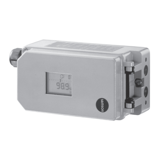
- Page 1 Electropneumatic Positioner Type 3730-2 Fig. 1 · Type 3730-2 Mounting and Operating Instructions EB 8384-2 EN Firmware version 1.3x Edition April 2005...
-
Page 2: Table Of Contents
Contents Contents Page Design and principle of operation ....8 Additional equipment ......9 Technical data . - Page 3 Contents Reset to default values ......54 Start-up via local interface (SSP) ....55 Status and diagnostic alarms .
- Page 4 Proper shipping and appropriate storage are assumed. Note! The device with a CE marking fulfils the requirements of the Directives 94/9/EC (ATEX) and 89/336/EEC (EMC). The declaration of conformity can be viewed and downloaded on the Internet at http://www.samson.de. EB 8384-2 EN...
- Page 5 Versions Type 3730-2 X X X X X 0 0 X 0 X 0 0 X 0 X X Article code Explosion protection Without II 2 G EEx ia IIC T6/II 2 D IP 65 T 80 °C acc. to ATEX...
- Page 6 Firmware modification Modifications of positioner firmware in comparison to previous versions Previous 1.01 1.10 Via the serial interface and the serial interface adapter, the positioner can be configured and operated using TROVIS-VIEW software. The following additional status indications were implemented: Code 76 - No emergency mode Code 77 - Program loading error Displays number of zero calibrations performed since the last initialization.
- Page 7 Firmware modification EB 8384-2 EN...
-
Page 8: Design And Principle Of Operation
The positioner basically consists of a travel The positioner is equipped with an interface sensor system that functions proportional to to allow the SAMSON TROVIS-VIEW Con- the resistance, an analog i/p module with figuration and Operator Interface software downstream booster as well as the electronic to transmit data and parameters over an unit with a microcontroller. -
Page 9: Additional Equipment
Design and principle of operation found in the Operating Instructions control valve moves to the fail-safe position EB 8388 EN. determined by the actuator, independent of the reference variable. Additional equipment Positioner with position transmitter As an option, the device can be additionally The position transmitter (13) is a two-wire equipped with a solenoid valve for forced transmitter and issues the travel sensor sig-... -
Page 10: Technical Data
Design and principle of operation Version with inductive limit switch The rotary shaft of the positioner carries an adjustable tag which actuates the installed proximity switch. The optional inductive limit switch (11) leads to A1 and the software limit switch, which remains in operation, leads to A2. - Page 11 FM/CSA non incendive Class I, Division 2, Group A, B, C, D, T6 Degree of protection IP 65 Communication (local) SAMSON SSP interface and serial interface adapter Software requirements TROVIS-VIEW with database module 3730-2 1 fault alarm contact, Binary contacts...
- Page 12 Design and principle of operation Solenoid valve SIL 4 approval acc. to IEC 61508 24 V DC reverse polarity protection, static destruction limit 40 V; − 5.6 V Input Current consumption I = (corresponding to 4.5 mA at 24 V) Ω...
-
Page 13: Attachment To The Control Valve - Mounting Parts And Accessories
The positioner can be attached either di- The positioner is standard equipped with the rectly to a SAMSON Type 3277 Actuator or lever M (pin position 35). according to IEC 60534-6 (NAMUR) to con- trol valves with cast yokes or rod-type yokes... - Page 14 Attachment to the control valve – Mounting parts and accessories Table 1 Direct attachment to Type 3277-5 Actuator, see Fig. 3 Order no. Mounting parts For actuators with 120 cm effective diaphragm area 1400-7452 Switchover plate (old) for Actuator Type 3277-5xxxxxx.00 (old) 1400-6819 Switchover plate new for Actuator Type 3277-5xxxxxx.01 (new) 1400-6822...
- Page 15 Attachment to the control valve – Mounting parts and accessories Attachment to NAMUR ribs or control valves with rod-type yokes (rod diameter Ø 35 mm or smaller) Table 3 according to IEC 60534-6, see Fig. 5 Travel in mm Lever For actuators Order no.
-
Page 16: Direct Attachment
Attachment to the control valve – Mounting parts and accessories Direct attachment left) pointing towards the signal pressure connection. Make sure that the bonded 2.1.1 Type 3277-5 Actuator gasket (14) points towards the actuator yoke. Refer to Table 1 on page 14 for the required 5. - Page 17 Attachment to the control valve – Mounting parts and accessories Lever Symbols 1.1 Nut Switchover plate (9) 1.2 Disk spring Actuator stem Follower pin extends Follower clamp Vent plug Attachment left Attachment right Stopper Connecting plate Actuator stem 6.1 Seal rings retracts Pressure gauge bracket Press.
-
Page 18: Type 3277 Actuator
Attachment to the control valve – Mounting parts and accessories 2.1.2 Type 3277 Actuator rests on the top of the follower clamp (3). Adjust the lever (1) correspondingly Refer to Table 2 on page 14 or the required and open the positioner cover to hold mounting parts as well as the accessories the positioner shaft in position at the cap with their order numbers. - Page 19 Attachment to the control valve – Mounting parts and accessories Lever 12.1 Screw 1.1 Nut 12.2 Stopper or connection for external piping 1.2 Disk spring Switch plate Follower pin Gasket 10 14 Follower clamp Formed seal 10 Cover plate Gasket 11 Cover 12 Connection block Lever M...
-
Page 20: Attachment According To Iec 60534-6
Attachment to the control valve – Mounting parts and accessories Attachment according to (8) on the positioner, making sure both seal rings (6.1) are seated properly. IEC 60534-6 4. Select required lever size (1) M, L or XL The positioner is attached to the control and pin position according to the actua- valve with a NAMUR bracket (10). - Page 21 Attachment to the control valve – Mounting parts and accessories Attachment to rod-type yoke Rods with Ø max. 35 mm Attachment to NAMUR rib Additional bracket for actuators with 2800 cm Lever XL and L and travel ≥ 60 mm Lever Disk spring 14.1...
-
Page 22: Attachment To Type 3510 Micro-Flow Valve
Attachment to the control valve – Mounting parts and accessories Attachment to Type 3510 Micro-flow Valve The positioner is attached to the valve yoke using a bracket. Refer to Table 3 on page 15 for the required mounting parts as well as the accessories with their order numbers. - Page 23 Attachment to the control valve – Mounting parts and accessories Lever Disk spring Follower pin Clamp Connecting clamp Seal rings Pressure gauge bracket Pressure gauge mounting kit Bracket Screw Important! Always use the connecting plate (6) included in the accessories to connect supply and output.
-
Page 24: Attachment To Rotary Actuators
(Ø5) included in the Prior to the attachment of the positioner to mounting kit and screw tight into the the SAMSON Type 3278 Rotary Actuator, bore for pin position 90°. you have to mount the associated adapter 7. - Page 25 Attachment to the control valve – Mounting parts and accessories (7, 8) 10.1 Important! Always use the connecting plate (6) included in the accessories to connect supply and output. Never screw threaded Control valve opens counterclockwise parts directly into the housing.
-
Page 26: Reversing Amplifier For Double-Acting Actuators
Attachment to the control valve – Mounting parts and accessories Reversing amplifier for Note! double-acting actuators The sealing plug (1.5) in the Type 3730 Positioner should not be unscrewed out of For the use with double-acting actuators, the the reversing amplifier. positioner must be fitted with a reversing The rubber seal (1.4) is not required and amplifier. - Page 27 Attachment to the control valve – Mounting parts and accessories From the positioner Output 38 Supply 9 Control signals to the actuator Connecting ring Reversing amplifer 1.1 Special screws 6.1 O-rings 1.2 Gasket 6.2 Screws 1.3 Special nuts 1.4 Rubber seal 1.5 Sealing plug 1.6 Filter Fig.
-
Page 28: Attaching An External Position Sensor
Attachment to the control valve – Mounting parts and accessories Attaching an external position sensor Refer to Table 6 on page 33 for a list of the mounting parts as well as the accessories re- quired for mounting the position sensor. Accessories for the pneumatic connection to the positioner housing can be found in Ta- ble 7. - Page 29 Attachment to the control valve – Mounting parts and accessories Type 3277 Actuator with 240 to 700 cm 2. Screw the position sensor (20) onto the mounting plate (21). The signal pressure is routed to the connec- 3. Depending on the actuator size and tion at the side of the actuator yoke for the rated travel of the valve, determine the version "Actuator stem extends".
-
Page 30: Mounting The Position Sensor With Attachment According To Iec 60534-6
Attachment to the control valve – Mounting parts and accessories 2.6.2 Mounting the position sensor Place the lever (1) in mid-position and hold it in place. Screw on the nut (1.1). with attachment according to 5. Place the follower clamp (3) on the actu- IEC 60534-6 ator stem, align and fasten it, making For the required mounting parts as well as... -
Page 31: Mounting The Position Sensor To Type 3510 Micro-Flow Valve
Attachment to the control valve – Mounting parts and accessories For other actuator sizes or travels, select the Place the lever (1) in mid-position and lever and pin position from the travel table hold it in place. Screw on the nut (1.1). on page 13. -
Page 32: Mounting The Position Sensor To Rotary Actuators
Attachment to the control valve – Mounting parts and accessories 2.6.4 Mounting the position sensor 4. Place the lever (1) and disk spring (1.2) on the sensor shaft. to rotary actuators Place the lever (1) in mid-position and For the required mounting parts as well as hold it in place. - Page 33 Attachment to the control valve – Mounting parts and accessories Table 6 Mounting parts for position sensor Order no. Direct attachment Mounting parts for actuators with 120 cm see Fig. 11 left 1400-7472 G 1/8 1400-6820 Connecting plate (9, old) for Actuator Type 3277-5xxxxxx.00 1/8 NPT 1400-6821...
-
Page 34: Connections
Connections Connections 3.1.1 Signal pressure gauges To monitor the supply air (Supply) and sig- Pneumatic connections nal pressure (Output), we recommend that pressure gauges be attached (see accesso- Caution! ries in Tables 1 to 4). The threads in the positioner housing are not designed for direct air connection! 3.1.2 Supply pressure The required supply air pressure depends... -
Page 35: Electrical Connections
Connections Electrical connections d = Seat diameter [cm] ∆p = Differential pressure across the valve [bar] For electrical installation, you are re- A = Actuator diaphragm area [cm quired to observe the relevant = Upper bench range of the actuator electrotechnical regulations and the [bar] accident prevention regulations that... - Page 36 Connections For the interconnection of equipment to en- Caution! ergy-limited circuits with type of protection The erroneous connection of a voltage EEx nL IIC, the permissible maximum values source of just around 7 V (or around 2 V specified in the statement of conformity or when connected to the wrong pole) can the addenda to the statement of conformity damage the positioner.
-
Page 37: Switching Amplifiers
Connections Connection for version with external posi- 3.2.1 Switching amplifiers tion sensor The terminal assignment is fixed by the con- For operation of the limit switches, switching nector of the connecting lead. amplifiers must be connected in the output circuit. To ensure the operating reliability of Shorten the connecting lead to the re- the positioner, the amplifiers should comply quired length and strip the insulation off. -
Page 38: Operation
Operation Operation Volume restriction Q The volume restriction is used to adapt the air delivery to the actuator size. Two fixed Note! settings are possible depending on how the A summary about operating and start up air is routed at the actuator: can be found in section 8 on page 61. - Page 39 Operation Displays and their meaning AUtO Automatic mode TunE Initialization in progress Maximum range Clockwise Available Not available Counterclockwise Zero calibration Nominal travel Error ää Escape Increasing/increasing äæ ix greater than 21.6 mA Increasing/decreasing Reset ix smaller than 2.4 mA Start Blinking Controlled operation w too low...
-
Page 40: Enabling And Selecting Parameters
Operation Enabling and selecting Note! parameters To cancel a value that you have just entered under a code, turn the button until ESC The codes which are marked with an aster- appears on the display and press to con- isk (*) in section 12 on page 66 onwards firm. -
Page 41: Operating Modes
Operation Operating modes Switching to manual operating mode Over Code 0 , press the button, AUtO 4.3.1 Automatic and manual appears in the display, Code 0 blinks. operating modes Turn button until MAN appears. Prior to initialization: If the positioner has not been initialized yet, the automatic operating AUtO cannot be se- lected. -
Page 42: Safe - Fail-Safe Position
Start-up and settings 4.3.2 SAFE – Fail-safe position Start-up and settings If you want to move the valve to fail-safe po- Note! sition, proceed as follows: A summary about start-up and operation can be found in section 8 on page 61. A leaflet including the same summary is also Select Code 0 , press the button, AUtO or... -
Page 43: Setting The Volume Restriction Q
Start-up and settings does not have any effect on the operation of Turn button until the display is ad- the positioner. justed to the desired direction, then con- firm reading direction by pressing the button. Setting the volume restriction Q For actuators smaller than 240 cm with Limiting the signal pressure... - Page 44 Start-up and settings confirm selected operating mode by Note! pressing the button. If the selected pin position is smaller than in- 3. Turn the button until Code 1 appears, tended for the respective travel range, the confirm Code 1 by pressing button.
-
Page 45: Initialization
Start-up and settings the initialization process has been com- Initialization pleted. See note at the end of this section. During initialization the positioner adapts it- self optimally to the friction conditions and Warning! the signal pressure demand of the control During initialization, the control valve. -
Page 46: Initialization Modes
Start-up and settings A malfunctioning leads to the process being The reference graphs are required for the canceled automatically. The initialization er- extended diagnostic functions of EXPERT ror appears on the display according to how it has been classified by the condensed 5.5.1 Initialization modes status. - Page 47 Start-up and settings Enable configuration: Note! For MAX initialization, the positioner cannot indicate nominal travel/angle of rotation in mm/°, Code 5 remains disabled. Default OFF In addition, the lower (Code 8) and the up- per (Code 9) x-range value can only be dis- played and modified in %.
- Page 48 Start-up and settings During the initialization procedure, the positioner checks whether the control valve can move through the indicated nominal Default 15 range (travel or angle) without collision. In case of a positive result, the indicated nominal range is adopted with the limits of →...
- Page 49 Start-up and settings MAN – Initialization based on a manually selected range Default MAX (with default upper x-range value by means of manual adjustment). Initialization mode just as NOM , however, for starting up valves with unknown nominal → Code 0 , press Turn range.
- Page 50 Start-up and settings After setting the AIR TO OPEN/CLOSE switch for the fail-safe position, setting the (substitute configuration, without initializa- volume restriction and pressing the INIT key, tion) the positioner calculates its configuration This initialization mode is an emergency data on the basis of the blocking position mode.
- Page 51 Start-up and settings Default MAX Default 7 → Code 6 , press → Code 17 Turn Turn → SUb , press turn Retain default. Proceed as follows only if known: → Select K Press , turn Default ää press → Code 7 , press Turn Default 2 →...
- Page 52 Start-up and settings be canceled and the positioner must be set to automatic operation AUtO as follows: Default 0.0 → Code 1 , press Press turn in order to move the valve slightly past the blocking position, then cancel me- →...
-
Page 53: Fault/Failure
Start-up and settings Fault/failure Display indicating an All status and fault alarms are assigned a error code classified status in the positioner. To provide a better overview, the classified alarms are summarized in a condensed After an error code has occurred, first try to status for the positioner (see section 6). -
Page 54: Zero Calibration
Start-up and settings Zero calibration Reset to default values In case of discrepancies with the closing po- This function resets all parameters to the fac- sition of the valve, e.g. with soft-sealed tory default values (see list of codes in sec- plugs, it may become necessary to tion 12). -
Page 55: Start-Up Via Local Interface (Ssp)
Status and diagnostic alarms Start-up via local interface Status and diagnostic alarms (SSP) The Type 3730-2 Positioner contains an in- tegrated diagnostic approach to generate The positioner must be supplied with at least classified status and diagnostic alarms. 4 mA. -
Page 56: Extended Expert + Diagnostics
Status and diagnostic alarms the positioner. Additionally, it is possible to Extended EXPERT diagnos- activate EXPERT at a later point in time in tics an existing positioner. For this purpose, an activation code can be In addition to the standard EXPERT diagnos- ordered, specifying the serial number of the tic features, the optional EXPERT extended... - Page 57 Status and diagnostic alarms Classification process in the positioner Status modification An alarm is assigned to one of following The classification of the status alarms can be classified states in the table: changed as required. They can be modified using TROVIS-VIEW Condensed status software over the local SSP interface.
- Page 58 Status and diagnostic alarms Logging and displaying diagnostic functions/alarms The last 30 alarms are logged in the positioner. However, it is important to note that the same alarm is only logged once when it first occurs. The alarms and the condensed states ap- pear on the display as described in the code list (section 12).
- Page 59 EB 8384-2 EN...
-
Page 60: Adjusting The Limit Switch
Adjusting the limit switch Setting the switching point: For CLOSED position: 1. Initialize positioner. Important! 2. Use the MAN function to move the During adjustment or testing, the switching positioner to 5 % (see LC display). point must always be approached from 3. -
Page 61: Quick Start-Up Guide
Mounting Make sure the lever can still move. Direct attachment Attachment to rotary actuators to SAMSON Type 3277 Actuator Lever M pin position 90° Travel mm Actuator cm Pin position Put the valve into the closed position, de- termine the opening direction. -
Page 62: Start-Up
Quick start-up guide Start-up Operation Selecting the parameters or values Connect pneumatic supply air (1.4 to Each parameter has a code number which 6 bar). is shown in the display. Use the button to Apply an electrical reference variable (4 to select. -
Page 63: Initialization
Quick start-up guide → Code 4, ↵ turn Initialization Select pin position, ↵ → Code 5 , ↵ turn Important! Perform a reset (Code 36) prior to each ini- Enter nominal travel/range, ↵ tialization → Code 6 , ↵ turn select NOM , ↵... -
Page 64: Retrofitting An Inductive Limit Switch
Retrofitting an inductive limit switch Retrofitting an inductive limit switch Required retrofit kit: Limit switch Order no. 1400-7460 1. Take off the rotary pushbutton (3) and cap (1), unthread the five fixing screws (2) and lift off the plastic cover (9). 2. -
Page 65: Maintenance
Maintenance Maintenance Servicing explosion-protected devices The positioner does not require any mainte- nance. If a part of the positioner on which the ex- plosion protection is based needs to be ser- There are filters with a 100 µm mesh size in viced, the positioner must not be put back the pneumatic connections for supply and into operation until an expert has inspected... -
Page 66: Code List
Code list Code list Parameter – Display, values Code Description [default setting] Important! Codes with marked with an asterisk (*) must be enabled with Code 3 prior to configuration. Operating mode AUtO = Automatic mode MAN = Manual mode SAFE = Fail-safe position ESC = Escape [MAN]... - Page 67 Code list Nominal range For initialization using NOM or SUb, the nominal travel/angle of rotation of the valve must be entered. [15.0] mm or angle ° The permissible adjustment range depends on the pin position according to the table for Code 4. After initialization has been successfully completed, the maximum nominal travel/angle reached on initialization is displayed.
- Page 68 Code list Upper x-range value Upper range travel/angle of rotation in the nominal or operating range. Value is displayed or must be entered. 20.0 to 100.0 [100.0] % The characteristic is adapted. nominal range, Example: The operating range is modified, for example, to limit Specified in mm or angle °...
- Page 69 Code list Final position w < If w approaches up to 1 % towards the final value that causes the valve to close, the actuator is immediately completely vented 0.0 to [1.0] % (with AIR TO OPEN) or filled with air (with AIR TO CLOSE). of the span adjusted via This action always lead to maximum tight-closing of the valve.
- Page 70 7: Segmented ball valve linear 3: Butterfly valve linear 8: Segmented ball valve eq. p. 4: Butterfly valve eq. percentage 9: User-defined * * Definition over SAMSON TROVIS-VIEW software w-ramp Open The time required to pass through the operating range when the valve opens.
- Page 71 Code list Alarm mode Switching mode of software limit switches alarm A1 and A2 in responding state (when positioner initialized). 0 to 3 [2] 1) Explosion-protected version according to EN 60947-5-6 0: A1 ≥ 2.1 mA A2 ≤ 1.2 mA 1: A1 ≤...
- Page 72 Code list Position transmitter x/ix Operating direction of the position transmitter; indicates how the travel/angle position is assigned to the output signal i, based on [ää] the closed position. äæ The operating range (see Code 8) of the valve is represented by the 4 to 20 mA signal.
- Page 73 Code list Reset Resets all parameters to default (factory setting). Note: After setting RUN, the positioner must be re-initialized. [OFF] Position transmitter Display only, indicates whether the position transmitter option is installed. Yes No Indicates whether the inductive limit switch option is installed or Inductive alarm not.
- Page 74 Code list Diagnostics Diagnostic parameters d0 Current temperature Operating temperature [°C] inside the positioner –55 to 125 d1 Minimum temperature The lowest temperature below 20 °C that has ever occurred. [20] d2 Maximum temperature The highest temperature above 20 °C that has ever occurred. [20] d3 Number of zero The number of zero calibrations since the last initialization.
- Page 75 Code list Error codes – Remedy Condensed status alarm active, when prompted, Err appears. Initialization error (indicated on the display by the condensed status with the corresponding classification) x < range The value supplied by the measuring signal is either too high or too low, the measuring sensor is close to its mechanical limit.
- Page 76 Init – Solenoid valve 1) A solenoid valve is installed (Code 45 = YES) and was not or not properly connected so that an actuator pressure could not be built up. The message appears when you attempt to initialize the positioner. 2) If you attempt to initialize the device from the fail-safe position (SAFE).
- Page 77 Remedy Return the positioner to SAMSON AG for repair. The reference variable is much smaller than 4 mA (0 %); occurs if...
- Page 78 Additional message at the fault Valve moves to the fail-safe position. alarm contact! Remedy Return the positioner to SAMSON AG for repair. The hardware positioner is monitored by means of a test calcula- Test calculation tion.
- Page 79 Code list Internal device error 1 Internal device error Remedy Return the positioner to SAMSON AG for repair. Parameter info Error in the parameter info which is not critical for the control. Remedy Confirm error. Check and, if necessary, reset required parameters.
-
Page 80: Setting With Trovis-View Software - Parameter List
Internet link to SAMSON’s activation server where a unique activation code will then be generated and displayed. Enter this activation code into TROVIS-VIEW’s Activation dialog box. The soft- ware is now ready for use without any restrictions in the purchased scope. - Page 81 Setting with TROVIS-VIEW software – Parameter list When the positioner is not connected, the default settings appear on the operator interface display or, alternatively, a stored TROVIS-VIEW file (*.tro) can be loaded and written over in the File menu by selecting Open . Connection to the positioner is established by clicking the symbols on top right on the button bar: Upload data from the positioner and displayed in the operator interface...
- Page 82 Setting with TROVIS-VIEW software – Parameter list 1. Start TROVIS-VIEW Make required settings in View menu by activating or deactivating functions. When the Trend Viewer is activated, all operating data are uploaded cyclically from the positioner in online mode and shown in the form of graphs. Right-click on the graph to edit the graph format or to copy the logged data to a file.
- Page 83 Setting with TROVIS-VIEW software – Parameter list 3. Select Communication from the Options menu and choose. communication settings. 4. Click on Port settings and select port as well as server setting. 5. Select Convert in the File menu to select the firmware version of the positioner.
-
Page 84: Setting The Parameters
Setting with TROVIS-VIEW software – Parameter list 13.3 Setting the parameters Click on one of the folders listed in the left column to open a window listing the settings of the corresponding parameters. Place the mouse arrow on the parameter name to open a tool tip providing information about that particular parameter. -
Page 85: Parameter List
Date that can be entered. Stored in the Date (month) January positioner Date (year) 1900...2155 2003 Certification Indicates whether the positioner can be used in hazardous area Identification – Positioner Device type 3730-2 Indicates exact model designation EB 8384-2 EN... - Page 86 Setting with TROVIS-VIEW software – Parameter list Identification – Positioner – Actuator Type identification Manufacturer ID number of the actuator that the actuator positioner is mounted upon Actuator type Single-acting Single-acting Actuator with or without spring return Double-acting mechanism Attachment Integral/ Integral Defines the attachment of the positioner on the...
- Page 87 Setting with TROVIS-VIEW software – Parameter list Parameter Values Default Description Valve dimensions DIN/ANSI Valve dimensions according to DIN or ANSI standard Nominal size DN 8...2100 Nominal size in mm (DIN) or inch (ANSI) Kvs coefficient 0.0001... 1.0000 Kv Valve flow coefficient 20000.0000 Kvs unit Kv/cv...
- Page 88 Setting with TROVIS-VIEW software – Parameter list Status Condensed state Summarized state of the positioner. The condensed status is made up from the var- ious states. The condensed status can take on the following states: No alarm Maintenance requirement Maintenance demand Failure Function check The condensed states “Maintenance require-...
- Page 89 Setting with TROVIS-VIEW software – Parameter list Parameter Value Default Description Positioner – Reference variable Direction of action Increasing/ Increasing/ Code 7 increasing >> increasing >> Incr./decr. <> Lower reference 0.0...75.0 % 0.0 % Code 12 range value Upper reference 25.0...100.0 % 100.0 % Code 13...
- Page 90 Setting with TROVIS-VIEW software – Parameter list Positioner – Characteristic Linear Code 20 Characteristic Linear selection Equal percentage Eq. perc. reverse SAMSON butterfly valves linear eq. perc. VETEC rotary plug valves linear eq. perc. Segmented ball valves linear eq. perc.
- Page 91 Setting with TROVIS-VIEW software – Parameter list Example for user-defined characteristic • Select User defined characteristic in Characteristic selection parameter. • Double-click on Edit, open or save characteristic to open a window where the characteristic can be edited. Click on Characteristic button on the bottom right to open and save a characteristic. EB 8384-2 EN...
- Page 92 Setting with TROVIS-VIEW software – Parameter list Parameter Values Default Description Positioner – Performance characteristics Required propor- 0...17 Code 17 tional-action coeffi- cient KP (step) Proportional-action Code 17 coefficient KP (step) Required deriva- Off/1/2/3/4 Code 18 tive-action time TV (step) Derivative-action Code 18 time TV (step)
- Page 93 Setting with TROVIS-VIEW software – Parameter list Enable limit value On/Off Code 26 Limit value A1 0.0...100.0 % 2.0 % Code 26 Enable limit value On/Off Code 27 Limit value A2 0.0...100.0 % 98.0 % Code 27 Fault alarm Yes/No Code 32 special functions Fault alarm...
- Page 94 Setting with TROVIS-VIEW software – Parameter list x > range Code 50 Delta x < range Code 51 Attachment Code 52 Initialization time Code 53 Determines the individual status exceeded for each alarm Initialization/ Code 54 solenoid valve with symbol Transit time not Code 55 achieved...
- Page 95 Setting with TROVIS-VIEW software – Parameter list Positioner – Start-up Reading direction Pneumatic Pneumatic Code 2 connection connection right/left right Pin position Code 4 17/25/35/50/ 70/100/200 mm 90° Initialization mode Nominal range Maximum Code 6 range Maximum range Manual adjust- ment Substitution Pressure limit...
- Page 96 Setting with TROVIS-VIEW software – Parameter list Positioner – Start-up – Initialization Initialization mode Nominal range Maximum Code 6 range Maximum range Manual adjust- ment Substitution Device initialized Status of device initialization Initialization Starting of initialization procedure. The initialization mode parameter must be first set to the required initialization procedure.
- Page 97 Setting with TROVIS-VIEW software – Parameter list Positioner – Maintenance Start zero calibration Zero calibration Starts zero calibration Initialization status Status of running initialization procedure Initialization Running initialization procedure has been can- canceled celed. The control valve moves to fail-safe posi- tion.
- Page 98 Setting with TROVIS-VIEW software – Parameter list Diagnosis – Status alarms Status Condensed status Alarm symbol Summarized condensed status. Made up from various states. Operating hours Time elapsed since first initialization counter Device in closed Time elapsed in closed loop since first initializa- loop tion Device switched on...
- Page 99 Setting with TROVIS-VIEW software – Parameter list Operation Control loop Code 57 Zero point Code 58 Autocorrection Code 59 Fatal error Code 60 Alarm w too small Code 63 Total valve travel Status of total valve travel limit exceeded Temperature Status alarm resulting from diagnosis analysis exceeded Hardware...
- Page 100 Setting with TROVIS-VIEW software – Parameter list Data memory Control parameter Code 68 Poti parameter Code 69 Calibration param- Code 70 eter General parameters Code 71 Alarm Internal device Code 73 error 1 Info parameter Code 75 Option parameter Code 78 Diagnostic Code 80 parameters...
- Page 101 Setting with TROVIS-VIEW software – Parameter list Diagnosis – Status alarms – Reset Reset absolute total Reset counter for absolute total valve travel travel back to 0 Reset Set back default values flag to 0 default values flag Resetting corresponding Reset Reset device status bit alarms...
- Page 102 Setting with TROVIS-VIEW software – Parameter list Reset data error Reset control pa- Code 68 rameter Reset poti param- Code 69 eter Resetting corresponding alarms Reset Code 71 general parameters Reset options pa- Code 78 rameter Reset diagnostic Code 80 parameters Reset statistical information Reset data logger...
-
Page 103: Dimensions In Mm
Dimensions in mm Dimensions in mm or connecting plate Pressure gauge External bracket position sensor NAMUR attachment Lever mm S = 17 M = 50 L = 100 XL = 200 Direct attachment M20 x 1.5 Output (38) Supply (9) Attachment to rotary actuators VDI/VDE 3845 for all sizes of fixing level 2... -
Page 104: Test Certificates
EB 8384-2 EN... - Page 105 EB 8384-2 EN...
- Page 106 EB 8384-2 EN...
- Page 107 EB 8384-2 EN...
- Page 108 EB 8384-2 EN...
- Page 109 EB 8384-2 EN...
- Page 110 EB 8384-2 EN...
- Page 111 EB 8384-2 EN...
- Page 112 EB 8384-2 EN...
- Page 113 EB 8384-2 EN...
- Page 114 EB 8384-2 EN...
- Page 115 EB 8384-2 EN...
- Page 116 EB 8384-2 EN...
- Page 117 EB 8384-2 EN...
- Page 118 EB 8384-2 EN...
- Page 119 EB 8384-2 EN...
- Page 120 SAMSON AG · MESS- UND REGELTECHNIK Weismüllerstraße 3 · 60314 Frankfurt am Main · Germany Phone: + 49 69 4009-0 · Fax: +49 69 4009-1507 EB 8384-2 EN Internet: http://www.samson.de...