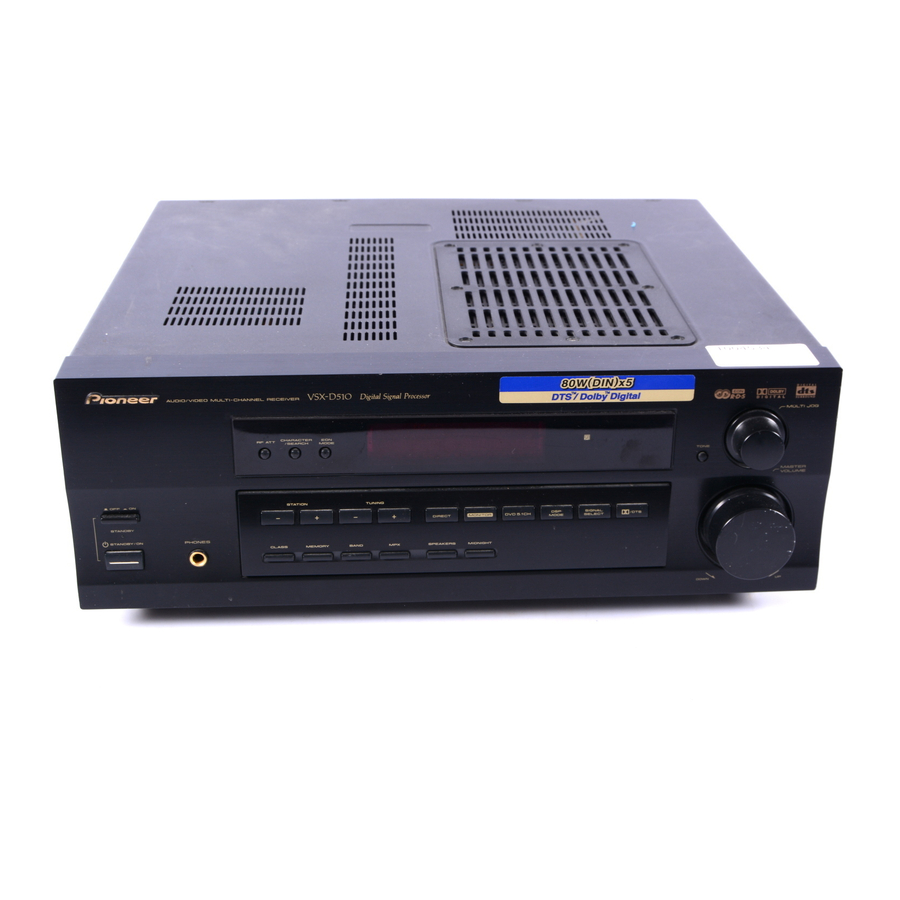
Pioneer VSX-D510 Operating Instructions Manual
Audio/video multi-channel receiver
Hide thumbs
Also See for VSX-D510:
- Operating instructions manual (72 pages) ,
- Service manual (61 pages) ,
- Manual (80 pages)
Table of Contents
Advertisement
Advertisement
Table of Contents

Related Manuals for Pioneer VSX-D510


Summary of Contents for Pioneer VSX-D510
- Page 1 AUDIO/VIDEO MULTI-CHANNEL RECEIVER VSX-D510 Operating Instructions...
-
Page 2: Important Notice
WARNING TO PREVENT FIRE OR SHOCK HAZARD, DO NOT EXPOSE THIS APPLIANCE TO RAIN OR MOISTURE. IMPORTANT The lightning flash with arrowhead symbol, within an equilateral triangle, is intended to alert the user to the presence of uninsulated "dangerous voltage" within the product's enclosure that may be of sufficient magnitude to constitute a risk of electric shock to persons. -
Page 3: Important Safety Instructions
IMPORTANT SAFETY INSTRUCTIONS READ INSTRUCTIONS — All the safety and operating instructions should be read before the product is operated. RETAIN INSTRUCTIONS — The safety and operating instructions should be retained for future reference. HEED WARNINGS — All warnings on the product and in the operating instructions should be adhered to. -
Page 4: Introductory Information
• Dry cell batteries (AA size IEC R6P) • Remote control • Operating instructions Using this Manual This manual is for the VSX-D510 audio/video multi- channel receivers. It is divided into two main sections: Set up This section covers installing your receiver and connecting up all the other components in your home theater system to it. -
Page 5: Table Of Contents
Contents Congratulations on buying this fine Pioneer product. Please read through these operating instructions so you will know how to operate your model properly. After you have finished reading the instructions, put them away in a safe place for future reference. -
Page 6: Connecting Your Equipment
Connecting Your Equipment Before making or changing the connections, switch off the power and disconnect the power cord from the AC outlet. Audio/Video Cords Use audio/video cords (not supplied) to connect the video components and a video cord to connect the monitor TV. -
Page 7: Connecting Audio Components
Connecting Audio Components To begin set up, connect your audio components to the jacks as shown below. These are all analog connections and your analog audio components (like a cassette deck) use these jacks. Remember that for components you want to record with, you need to hook up four plugs (a set of stereo ins and a set of stereo outs), but for components that only play, you only need to hook up one set of stereo plugs (two plugs). -
Page 8: Connecting Video Components
Connecting Your Equipment Connecting Video Components Connect your video components to the jacks as shown below. Regarding digital video components (like a DVD player), you must use the analog connections pictured on this page for the video signal but in order to hear a digital source (like a DVD) you should hook up their audio to a digital input (see page 6). -
Page 9: Connecting Your Equipment 6
Connecting Antennas Connect the AM loop antenna and the FM wire antenna as shown below. To improve reception and sound quality, connect external antennas (see Using external antennas, below). Always make sure that the receiver is switched off and unplugged from the wall outlet before making or changing any connections. AM LOOP ANTENNA CONTROL... -
Page 10: Connecting Speakers
Connecting Your Equipment Connecting Speakers A full complement of six speakers is shown here but, naturally, everyone’ s home setup will vary. Simply connect the speakers you have in the manner described below. The receiver will work with just two stereo speakers (called “front” speakers in the diagram) but using at least three speakers is recommended, and all five is best. -
Page 11: Speaker Terminals
Speaker terminals Use good quality speaker wire to connect the speakers to the receiver. 1 Twist around 1/2 inch of bare wire strands together. 2 Unclip the speaker terminal and insert the wire. 3 Snap shut the speaker terminal to secure. 1/2 inches Caution: Make sure that all the bare speaker wire is twisted together and inserted fully into the speaker terminal. -
Page 12: Ac Outlet [Switched 100 W (0.8 A) Max]
A damaged power cord can cause a fire or give you an electrical shock. Check the power cord once in a while. When you find it damaged, ask your nearest PIONEER authorized service center or your dealer for a replacement. Operating Other Pioneer Components By connecting a control cord (optional), you can control other Pioneer equipment using this remote control unit. -
Page 13: Preparations
Preparations Setting Up for Surround Sound Switch the power of this unit on (The STANDBY indicator goes out). To ensure the best possible surround sound, be sure to complete the following set up operations. This is particularly important when using the 2 (Dolby) surround mode. -
Page 14: Speakers Setting Mode
Preparations SPEAKERS (Front, Center, Surround) setting mode This setting establishes the configuration of the speaker system and size of each set of speakers you have connected. So, for example, here you set whether you have connected surround speakers or not, and how big they are. -
Page 15: Center Speaker Distance Setting
MEMO: • The initial setting is “ ”. 100 Hz • If all speakers (front, center, and surround) are set to “Large” in SPEAKERS setting mode, the crossover frequency cannot be set because there are no “Small” speakers ( appears in the display). LFE attenuator setting mode Dolby Digital and DTS audio sources include ultra-low bass tones. -
Page 16: Dual Mono Setting
Preparations SURROUND speakers distance setting mode Use to set the SURROUND speakers distance. Like the CENTER speaker position, the SURROUND speakers may be set in a location closer or farther than the FRONT speakers. Set the distance of the SURROUND speakers accurately to hear sounds coming from both FRONT and SURROUND speakers at the same time. -
Page 17: Setting The Volume Level Of Each Channel
Coaxial digital input setting Here you tell the receiver what component you have hooked up to the coaxial digital input jack. Press % or fi to select the coaxial digital input (DVD, TV, CD, CD-R, VCR or OFF). After you assign a component to the digital jack, whenever you select that component, for example a DVD player, the receiver will automatically change to the digital input setting. -
Page 18: Displays & Controls
Displays & Controls Front Panel ST ANDBY ST ANDBY/ON 1 STATION (+/–) buttons (see page 27) Selects station memories when using the tuner. 2 TUNING buttons (see page 26) Selects the frequency when using the tuner. 3 DIRECT button Use to switch DIRECT playback on or off. This mode bypasses the tone controls and channel levels for the most accurate reproduction of a source. -
Page 19: Display
Display SIGNAL SELECT DIGITAL DTS ANALOG DIGITAL 1 SIGNAL SELECT indicators Lights to indicate the type of input signal assigned for the current component : 2 DIGITAL : Lights when a DOLBY DIGITAL signal is played. DTS : Lights when a source with DTS audio signals is played. -
Page 20: Remote Control
Displays & Controls Remote Control MULTI CONTROL DVD/LD TV/SAT VCR/DVR RECEIVER TUNER DSP MODE MIDNIGHT 5.1CH CHANNEL TEST SELECT TONE CHANNEL LEVEL FUNC TV CONTROL MENU SOURCE CLASS D.ACCESS ¡ LOUDNESS FUNCTION MUTING RECEIVER DIMMER AUDIO/VIDEO PRE-PROGRAMMED REMOTE CONTROL UNIT 1 MULTI CONTROL buttons Use to put the receiver/remote control in the stated mode. - Page 21 7 THE FOLLOWING BUTTONS ARE BOTH CONTROLS FOR OTHER COMPONENTS (LIKE A DVD PLAYER) AND DEDICATED TUNER CONTROLS. THE TUNER CONTROLS ARE EXPLAINED HERE. YOU CAN USE THEM AFTER YOU HAVE PUSHED THE TUNER MULTI CONTROL BUTTON. CLASS button (see page 27) Use to switch between the three banks (classes) of station memories.
-
Page 22: Sound Modes
Sound Modes Learning about the Sound Modes The sound modes are explained here. There are two cinema modes: STANDARD, and ADVANCED THEATER. These are designed to be used with multi channel surround sound audio/visual sources (like DVDs and LDs). Intrinsic to home theater, these modes can deliver realistic and powerful surround sound that recreates the movie theater experience. -
Page 23: Switching Analog/Digital Signal Input
Switching ANALOG/DIGITAL Signal Input When you select a function (for example CD) that is only hooked up by a digital connection, then the ANALOG/DIGITAL signal input switch will automatically choose digital. If you have that function hooked up by both digital and analog connections this switch lets you choose which to listen to. -
Page 24: Selecting A Sound Mode
Sound Modes Selecting a Sound Mode To ensure the best possible surround sound, be sure to complete the set up procedures described in “Setting Up for Surround Sound” (starting on page 13) before using the sound modes. This is particularly important when using the 2 (Dolby) surround mode. -
Page 25: Advanced Theater Mode (Dolby/Dts Mode)
ADVANCED THEATER Mode (Dolby/DTS mode) Switch on the Dolby/DTS mode by pressing the 2 button. When Dolby/DTS mode is ON, Dolby Pro Logic, Dolby Digital and DTS, and signal processing is performed automatically corresponding to the input signal. Use this button to cycle through the various modes. -
Page 26: Using The Tuner
Using the Tuner Finding a Station The following steps show you how to tune in to FM and AM radio broadcasts using the automatic (search) and manual (step) tuning functions. If you already know the exact frequency of the station you want to listen to, see Tuning Directly to a Station below. -
Page 27: Memorizing Stations
This saves the effort of manually tuning in each time. The VSX-D510 can memorize up to 30 stations, stored in three banks, or classes, (A, B and C) of 10 stations each. -
Page 28: Making A Recording
Making a Recording Making an Audio or a Video Recording The following steps show you how to make an audio or a video recording from the built in tuner, or from an audio or video source connected to the receiver (such as a CD player or TV). -
Page 29: Controlling The Rest Of Your System
Controlling the Rest of Your System Setting Up the Remote Control Recalling preset codes The following steps show you how to recall preset codes for each button. Once the preset code MULTI CONTROL is assigned, pressing the button will automatically set the remote to operate the respective component. -
Page 30: Clearing All The Remote Control Settings
Controlling the Rest of Your System MEMO • When operating a PIONEER DVD/LD player, set the manufacturer code to “ • All codes enrolled in the manufacturer code list can be set even if a code is not displayed. • TUNER cannot be preset. -
Page 31: Cd/Md/Cd-R/Vcr/Dvd/Ld/Dvr Player/Cassette Deck Controls
CD/MD/CD-R/VCR/DVD/LD/DVR Player/Cassette Deck Controls This remote control can control these components after entering the proper codes (see p.29-30). Use the buttons to put the remote control in the stated mode. MULTI CONTROL o l l ¢ ¡ l l i y l t o l l fi... -
Page 32: Cable Tv/Satellite Tv/Tv/Dtv Controls
– / MEMO: • The first four buttons for the VSX-D510 are dedicated to control the TV assigned to the only have one TV to hook up to this system assign it to the assign the main TV to the be accessible. -
Page 33: Preset Code List
Preset Code List Controlling the Rest of Your System... -
Page 34: Additional Information
If the trouble cannot be rectified even after exercising the checks listed below, ask your nearest PIONEER authorized service center or your dealer to carry out repair work. The power does not turn ON. -
Page 35: Specifications
Specifications Amplifier Section Continuous average power output of 100 watts* per channel, min., at 8 ohms, from 20 Hz to 20,000 Hz with no more than 0.2 %** total harmonic distortion (front). Continuous Power Output Front ... 100 W per channel (1kHz, 1.0 %, 8 ) Center ... - Page 36 PIONEER ELECTRONICS OF CANADA, INC. PIONEER EUROPE NV Haven 1087, Keetberglaan 1, B-9120 Melsele, Belgium TEL: 03/570.05.11 PIONEER ELECTRONICS AUSTRALIA PTY. LTD. PIONEER ELECTRONICS DE MEXICO S.A. DE C.V. <TSWZW/00K00001> We Want You Listening For A Lifetime Want You Used wisely, your new sound equipment will provide a lifetime of...