Advertisement
Quick Links
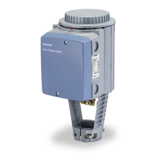
SKD62UA Series Electronic Valve Actuator,
Advanced Features
Product Description
The SKD62UA electronic valve actuator requires a 24
Vac supply and receives a 0 to 10 Vdc or 4 to 20 mA
control signal to proportionally control a valve. These
actuators are designed to work with the Flowrite™
VF599 series valves, or other manufacturer's valves
with fitted with the appropriate Universal Valve Retrofit
Kit.
Product Numbers
SKD62UA
Warning/Caution Notations
WARNING:
CAUTION:
Required Tools
•
5 mm hex wrench
•
Small and medium flat-blade screwdrivers
Expected Installation Time
20 minutes for factory installed actuator
45 minutes for field replacement of actuator
Prerequisites
WARNING:
If mounting the actuator to a valve
already in line, either close the shut-off
valves in the piping (upstream first,
then downstream) or switch off the
pump to allow the differential and static
pressure in the valve to drop.
Item Code: 129-369, Rev. 011
Personal injury or loss of life
may occur if you do not follow a
procedure as specified.
Equipment damage, or loss of
data may occur if you do not
follow a procedure as specified.
Installation Instructions
Mounting Positions
Figure 1. Acceptable Mounting Positions.
Using the Weather Shield
The SKD62UA must be in the vertical position.
Complete instructions for the mounting of the weather
shield are included with that product.
NOTE: Use the top knockout position when installing
the Weather Shield. See Figure 13.
VENTILATION
OPENINGS
Figure 2. Weather Shield Installation Position.
Document No. 129-369
October 16, 2002
Not allowed with the
Weather Shield
Not allowed in
any circumstance
VENTILATION
OPENINGS
Page 1 of 6
Advertisement

Related Manuals for Siemens SKD62UA


Summary of Contents for Siemens SKD62UA
- Page 1 Advanced Features Product Description Mounting Positions The SKD62UA electronic valve actuator requires a 24 Vac supply and receives a 0 to 10 Vdc or 4 to 20 mA control signal to proportionally control a valve. These actuators are designed to work with the Flowrite™...
-
Page 2: Installation
«AUTO « ≈5 x 360° 5 mm Figure 4. NOTE: Make sure the yoke nuts are loose enough to allow the actuator to slip over the bonnet. See Figure 5. Figure 8. Page 2 of 6 Siemens Building Technologies, Inc. -
Page 3: Wiring Diagrams
0 to 10 Vdc Default (Factory Settings) *Changing the default setting will modify an equal percentage valve to a linear flow characteristic. When set to default, the flow characteristic is determined by the valve body. Siemens Building Technologies, Inc. Page 3 of 6... -
Page 4: Connecting Terminals
24 Vac. The calibration procedure can be repeated as often as necessary. To initiate the calibration procedure, short circuit the contacts inside the slot located on the printed circuit board (with a screwdriver). Page 4 of 6 Siemens Building Technologies, Inc. -
Page 5: Manual Operation
(19) Document Technical Instruction Number EA599-18 Flowrite 599 Series SKB/C/D 62UA Series Electronic Valve Actuator, 24 155-717 (126) Vac Proportional Control Advanced Features Figure 13. 599-10071 Weather Shield Dimensions in Inches (Millimeters). Siemens Building Technologies, Inc. Page 5 of 6... - Page 6 Information in this publication is based on current specifications. The company reserves the right to make changes in specifications and models as design improvements are introduced. Flowrite is a trademark of Siemens Building Technologies, Inc. Other product or company names mentioned herein may be the trademarks of their respective owners.