Dell EMC PowerEdge T440 Installation And Service Manual
Hide thumbs
Also See for EMC PowerEdge T440:
- Installation and service manual (115 pages) ,
- Simple operation manual (9 pages) ,
- Manual (150 pages)

Related Manuals for Dell EMC PowerEdge T440


Summary of Contents for Dell EMC PowerEdge T440
- Page 1 Dell EMC PowerEdge T440 Installation and Service Manual Regulatory Model: E30S Series Regulatory Type: E30S002...
- Page 2 A WARNING indicates a potential for property damage, personal injury, or death. Copyright © 2017 Dell Inc. or its subsidiaries. All rights reserved. Dell, EMC, and other trademarks are trademarks of Dell Inc. or its subsidiaries. Other trademarks may be trademarks of their respective owners.
-
Page 3: Table Of Contents
Ports and connectors specifications..........................35 USB ports................................... 35 NIC ports..................................35 VGA ports................................... 35 Serial connector................................. 35 Internal Dual microSD Module or vFlash card......................36 Video specifications................................. 36 Environmental specifications............................36 Standard operating temperature..........................37 Dell EMC PowerEdge T440 Installation and Service Manual Contents... - Page 4 Removing the system feet............................70 Installing the system feet............................71 Caster wheels – optional..............................72 Removing caster wheels............................72 Installing caster wheels..............................73 System cover..................................74 Removing the system cover............................. 74 Installing the system cover............................75 Dell EMC PowerEdge T440 Installation and Service Manual Contents...
- Page 5 Expansion card holder..............................113 Removing the expansion card holder........................113 Installing the expansion card holder........................114 Expansion cards................................114 Expansion card installation guidelines........................114 GPU card installation guidelines..........................116 Removing a expansion card............................. 116 Dell EMC PowerEdge T440 Installation and Service Manual Contents...
- Page 6 8 Using system diagnostics........................... 149 Dell Embedded System Diagnostics..........................149 Running the Embedded System Diagnostics from Boot Manager..............149 Running the Embedded System Diagnostics from the Dell Lifecycle Controller..........149 System diagnostic controls............................. 150 Dell EMC PowerEdge T440 Installation and Service Manual...
- Page 7 Disabling forgotten password..........................152 System board jumpers and connectors........................153 10 Getting help..............................155 Contacting Dell................................155 Accessing system information by using QRL......................155 Quick Resource Locator for T440.......................... 156 Receiving automated support with SupportAssist ....................156 Dell EMC PowerEdge T440 Installation and Service Manual Contents...
-
Page 8: Dell Emc Poweredge T440 Overview
Front view of the system • Back view of the system Supported configurations for the PowerEdge T440 system The Dell EMC PowerEdge T440 system supports the following configurations: Dell EMC PowerEdge T440 Installation and Service Manual Dell EMC PowerEdge T440 overview... - Page 9 Figure 1. Supported configurations for a PowerEdge T440 system Dell EMC PowerEdge T440 Installation and Service Manual Dell EMC PowerEdge T440 overview...
-
Page 10: Front View Of The System
Front view of the system The front panel view of the systems. Figure 2. Front panel view of a 4 x 3.5 inch cabled drive system Dell EMC PowerEdge T440 Installation and Service Manual Dell EMC PowerEdge T440 overview... - Page 11 Figure 3. Front panel view of a 8 x 3.5-inch hot swappable drive system Dell EMC PowerEdge T440 Installation and Service Manual Dell EMC PowerEdge T440 overview...
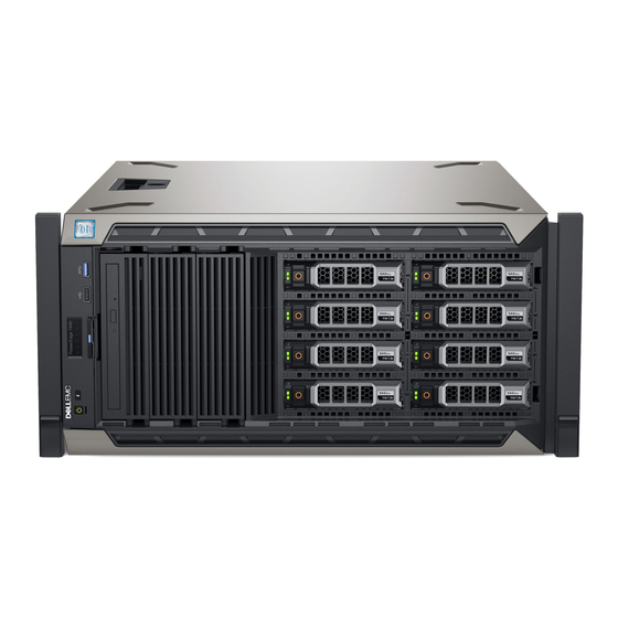
- Page 12 Figure 4. Front panel view of a 8 x 3.5-inch hot swappable drive system in rack mode Dell EMC PowerEdge T440 Installation and Service Manual Dell EMC PowerEdge T440 overview...
- Page 13 The System Identification (ID) button is available on the front and back of the systems. Press the button to identify a system in a rack by turning on the button Dell EMC PowerEdge T440 Installation and Service Manual Dell EMC PowerEdge T440 overview...
-
Page 14: Status Led Indicators
Enables you to convert the tower system to a rack system. Related link Status LED indicators Technical specifications Status LED indicators NOTE: The indicators display solid amber if any error occurs. Figure 6. Status LED indicators Dell EMC PowerEdge T440 Installation and Service Manual Dell EMC PowerEdge T440 overview... - Page 15 If the problem persists, see the Getting help section. NOTE: For more information about the supported PCIe cards, see the Expansion card installation guidelines section. Related link Getting help Expansion card installation guidelines Dell EMC PowerEdge T440 Installation and Service Manual Dell EMC PowerEdge T440 overview...
-
Page 16: System Health And System Id Indicator Codes
Blinking amber Indicates that the system is experiencing a fault. Check the System Event Log for specific error messages. For more information about error messages, see the Dell Event and Error Messages Reference Guide at Dell.com/openmanagemanuals > OpenManage software. Related link... -
Page 17: Drive Indicator Codes
Flashes green slowly Drive rebuilding. Solid green Drive online. Flashes green for three seconds, amber for three seconds, and Rebuild stopped. then turns off after six seconds Dell EMC PowerEdge T440 Installation and Service Manual Dell EMC PowerEdge T440 overview... -
Page 18: Back View Of The System
For more information about the PSU configurations, see the Technical Specifications section Enables you to remotely access iDRAC. For more information, see the iDRAC9 Enterprise port iDRAC User’s Guide at Dell.com/idracmanuals. Dell EMC PowerEdge T440 Installation and Service Manual Dell EMC PowerEdge T440 overview... -
Page 19: Nic Indicator Codes
NIC, and the link LED indicator indicates the speed of the connected network. Figure 10. NIC indicator codes link LED indicator activity LED indicator Dell EMC PowerEdge T440 Installation and Service Manual Dell EMC PowerEdge T440 overview... -
Page 20: Power Supply Unit Indicator Codes
Blinking green and turns off When hot-plugging a PSU, the PSU handle blinks green five times at a rate of 4 Hz and turns off. This indicates a PSU mismatch with respect to efficiency, feature set, health status, or supported voltage. Dell EMC PowerEdge T440 Installation and Service Manual Dell EMC PowerEdge T440 overview... - Page 21 CAUTION: If two PSUs are used, they must be of the same type and have the same maximum output power. Dell EMC PowerEdge T440 Installation and Service Manual Dell EMC PowerEdge T440 overview...
-
Page 22: Diagnostic Indicators
Run the appropriate Online Diagnostics test. Restart the system and run embedded diagnostics (ePSA). • If the drives are configured in a RAID array, restart the system, and enter the host adapter configuration utility program. Dell EMC PowerEdge T440 Installation and Service Manual Diagnostic indicators... -
Page 23: System Health And System Id Indicator Codes
ID mode. Blinking blue Indicates that the system ID mode is active. Press the system health and system ID button to switch to system health mode. Dell EMC PowerEdge T440 Installation and Service Manual Diagnostic indicators... -
Page 24: Drive Indicator Codes
Blinking amber Indicates that the system is experiencing a fault. Check the System Event Log for specific error messages. For more information about error messages, see the Dell Event and Error Messages Reference Guide at Dell.com/openmanagemanuals > OpenManage software. Related link... -
Page 25: Power Supply Unit Indicator Codes
Swapping the PSU to make a matched pair can result in an error condition and unexpected system shutdown. To change from a high output configuration to a low output configuration or vice versa, you must turn off the system. Dell EMC PowerEdge T440 Installation and Service Manual Diagnostic indicators... -
Page 26: Nic Indicator Codes
Enhanced Preboot System Assessment If you experience a problem with your system, run the system diagnostics before contacting Dell for technical assistance. The purpose of running system diagnostics is to test your system hardware without requiring more equipment or risking data loss. If you are unable to fix the problem yourself, service and support personnel can use the diagnostics results to help you solve the problem. - Page 27 To run the embedded system diagnostics from Boot Manager: As the system boots, press <F11>. Using the arrow keys select System Utilities → Launch Diagnostics. Wait while the Quick Tests automatically run. Dell EMC PowerEdge T440 Installation and Service Manual Diagnostic indicators...
-
Page 28: Locating The Service Tag Of Your System
Click OK when prompted, and the system reboots. Running the Embedded System Diagnostics from the Dell Lifecycle Controller To run the embedded system diagnostics from the Dell Lifecycle Controller: As the system boots, press F10. Select Hardware Diagnostics → Run Hardware Diagnostics. - Page 29 Enterprise Service Tag (EST) is found on the back of the system. This information is used by Dell to route support calls to the appropriate personnel. Dell EMC PowerEdge T440 Installation and Service Manual Diagnostic indicators...
-
Page 30: Documentation Resources
For information about installing and using Dell Dell.com/serviceabilitytools SupportAssist, see the Dell EMC SupportAssist Enterprise User’s Guide. For understanding the features of Dell Lifecycle Dell.com/idracmanuals Controller, see the Dell Lifecycle Controller User’s Guide. Dell EMC PowerEdge T440 Installation and Service Manual Documentation resources... - Page 31 Dell Event and Error Messages Reference Guide. Troubleshooting your system For information about identifying and Dell.com/poweredgemanuals troubleshooting the PowerEdge server issues, see the Server Troubleshooting Guide. Dell EMC PowerEdge T440 Installation and Service Manual Documentation resources...
-
Page 32: Technical Specifications
Processor specifications • PSU specifications • System battery specifications • Expansion bus specifications • Storage controller specifications • Drive specifications • Ports and connectors specifications • Video specifications • Environmental specifications Dell EMC PowerEdge T440 Installation and Service Manual Technical specifications... -
Page 33: System Dimensions
464.362 mm 471.333 mm 538.4 mm 573.636 mm 37.065 mm (12.12 in) (16.94 in) (18.28 in) (17.37 in) (21.19 in) (22.58 in) (1.45 in) (without bezel) 21.165 mm (0.83 in) Dell EMC PowerEdge T440 Installation and Service Manual Technical specifications... -
Page 34: Chassis Weight
PowerEdge RAID Controller(PERC) 9: Internal storage controller cards: H330P+, PERC H730P+, HBA330+ • PERC 10: External storage controller cards: H840 and 12 Gbps Ext SAS HBA • PERC10: Internal storage controller cards: H740P Dell EMC PowerEdge T440 Installation and Service Manual Technical specifications... -
Page 35: Drive Specifications
Serial connector The T440 system supports one serial connector on the back panel, which is a 9-pin connector, Data Terminal Equipment (DTE), 16550- compliant. Dell EMC PowerEdge T440 Installation and Service Manual Technical specifications... -
Page 36: Internal Dual Microsd Module Or Vflash Card
IDSDM The IDSDM/vFlash card sits in the back of the system, in a Dell-proprietary slot. IDSDM/vFlash card supports three micro SD cards (two cards for IDSDM and one card for vFlash). MicroSD cards capacity for IDSDM are 16/32/64 GB while for vFlash the microSD card capacity is 16 GB. -
Page 37: Standard Operating Temperature
Table 25. Standard operating temperature specifications Standard operating temperature Specifications Continuous operation (for altitude less than 950 m or 3117 10°C to 35°C (50°F to 95°F) with no direct sunlight on the equipment. Dell EMC PowerEdge T440 Installation and Service Manual Technical specifications... -
Page 38: Expanded Operating Temperature
Two non-redundant power supply units are required. • Two non-redundant system fans are required. • Non-Dell qualified peripheral cards and/or peripheral cards greater than 25 W are not supported. • GPU is not supported. • Tape backup unit is not supported. - Page 39 Copper coupon corrosion rate <300 Å/month per Class G1 as defined by ANSI/ISA71.04-2013. Silver coupon corrosion rate <200 Å/month as defined by ANSI/ISA71.04-2013. NOTE: Maximum corrosive contaminant levels measured at ≤50% relative humidity. Dell EMC PowerEdge T440 Installation and Service Manual Technical specifications...
-
Page 40: Initial System Setup And Configuration
The Integrated Dell Remote Access Controller (iDRAC) is designed to make system administrators more productive and improve the overall availability of Dell systems. iDRAC alerts administrators to system issues, helps them perform remote system management, and reduces the need for physical access to the system. -
Page 41: Log In To Idrac
Ensure that you change the default user name and password after setting up the iDRAC IP address. For more information about logging in to the iDRAC and iDRAC licenses, see the latest Integrated Dell Remote Access Controller User's Guide at Dell.com/idracmanuals. -
Page 42: Downloading Drivers And Firmware
Using Dell OpenManage Deployment Toolkit (DTK) Dell.com/openmanagemanuals Downloading drivers and firmware Dell recommends that you download and install the latest BIOS, drivers, and systems management firmware on your system. Prerequisite Ensure that you clear the web browser cache before downloading the drivers and firmware. -
Page 43: Pre-Operating System Management Applications
You can access system setup by using two methods: • Standard graphical browser—The browser is enabled by default. • Text browser—The browser is enabled by using Console Redirection. Related link System Setup details Viewing System Setup Dell EMC PowerEdge T440 Installation and Service Manual Pre-operating system management applications... -
Page 44: Viewing System Setup
The iDRAC settings utility is an interface to set up and configure the iDRAC parameters by using UEFI (Unified Extensible Firmware Interface). You can enable or disable various iDRAC parameters by using the iDRAC settings utility. For more information about this utility, see Integrated Dell Remote Access Controller User’s Guide at Dell.com/idracmanuals. -
Page 45: System Bios
RAID array, you must set both this field and the Embedded SATA field on the SATA Settings menu to RAID mode. You might also need to change the Boot Mode setting to UEFI. Otherwise, you should set this field to Non-RAID mode. Dell EMC PowerEdge T440 Installation and Service Manual Pre-operating system management applications... -
Page 46: System Information
Specifies the BIOS version installed on the system. Version System Specifies the current version of the Management Engine firmware. Management Engine Version System Service Tag Specifies the system Service Tag. Dell EMC PowerEdge T440 Installation and Service Manual Pre-operating system management applications... - Page 47 Specifies the amount of video memory. System Memory Specifies whether the system memory tests are run during system boot. Options are Enabled and Disabled. This Testing option is set to Disabled by default. Dell EMC PowerEdge T440 Installation and Service Manual Pre-operating system management applications...
-
Page 48: Processor Settings
Enables you to govern the frequency of the communication links among the CPUs in the system. Speed NOTE: The standard and basic bin processors support lower link frequencies. Dell EMC PowerEdge T440 Installation and Service Manual Pre-operating system management applications... - Page 49 Processor n NOTE: Depending on the number of CPUs, there might be up to n processors listed. The following settings are displayed for each processor installed in the system: Dell EMC PowerEdge T440 Installation and Service Manual Pre-operating system management applications...
- Page 50 For AHCI Mode or RAID Mode, BIOS support is always enabled. Option Description Model Specifies the drive model of the selected device. Drive Type Specifies the type of drive attached to the SATA port. Dell EMC PowerEdge T440 Installation and Service Manual Pre-operating system management applications...
-
Page 51: Boot Settings
Specifies the drive that is booted in the event of a drive failure. The devices are selected in the Hard-Disk Drive Sequence on the Boot Option Setting menu. When this option is set to Disabled, only the first drive in the list is Dell EMC PowerEdge T440 Installation and Service Manual Pre-operating system management applications... - Page 52 Operating systems must be UEFI-compatible to be installed from the UEFI boot mode. DOS and 32-bit operating systems do not support UEFI and can only be installed from the BIOS boot mode. NOTE: For the latest information about supported operating systems, go to Dell.com/ossupport. Changing boot order About this task You may have to change the boot order if you want to boot from a USB key.
-
Page 53: Network Settings
UEFI boot option is created for the iSCSI device automatically. This is set to Disabled by default. iSCSI Device1 Settings Enables you to control the configuration of the iSCSI device. Dell EMC PowerEdge T440 Installation and Service Manual Pre-operating system management applications... - Page 54 If your operating system begins to load before you press F2, wait for the system to finish booting, and then restart your system and try again. On the System Setup Main Menu screen, click System BIOS. Dell EMC PowerEdge T440 Installation and Service Manual Pre-operating system management applications...
- Page 55 When Internal SD Card Redundancy is set to Disabled, only the primary SDMicroSD card is visible to the OS. This option is set to Disabled by default. Dell EMC PowerEdge T440 Installation and Service Manual Pre-operating system management applications...
- Page 56 Table 33. Slot Bifurcation Option Description Auto Discovery Bifurcation Settings Platform Default Bifurcation , Auto Bifurcation, and Manual bifurcation Slot 1 Bifurcation x4 Bifurcation x4 Bifurcation Slot 2 Bifurcation Dell EMC PowerEdge T440 Installation and Service Manual Pre-operating system management applications...
- Page 57 Enables you to associate the External Serial Connector to Serial Device 1, Serial Device 2, or the Remote Access Connector Device by using this option. This option is set to Serial Device 1 by default. Dell EMC PowerEdge T440 Installation and Service Manual Pre-operating system management applications...
- Page 58 You can only change the rest of the options if the mode is set to Custom.This option is set to Performance Per Watt Optimized (DAPC) by default. DAPC is Dell Active Power Controller.Other options include Performance Per Watt (OS), Performance, and Workstation Performance.
- Page 59 Bus Link Power Management PCI ASPM L1 Link Enables or disables the PCI ASPM L1 Link Power Management. This option is set to Enabled by default. Power Management Dell EMC PowerEdge T440 Installation and Service Manual Pre-operating system management applications...
-
Page 60: System Security
TPM Security must be enabled with Pre-boot measurements. This option is set to Off by default. Power Button Enables or disables the power button on the front of the system. This option is set to Enabled by default. Dell EMC PowerEdge T440 Installation and Service Manual Pre-operating system management applications... -
Page 61: Options Description
BIOS performs signature verification on programmatic attempts to update policy objects. Deployed Mode restricts the programmatic mode transitions. Secure Boot Policy Specifies the list of certificates and hashes that secure boot uses to authenticate images. Summary Dell EMC PowerEdge T440 Installation and Service Manual Pre-operating system management applications... -
Page 62: Using Your System Password To Secure Your System
Even after you turn off and restart the system, the error message is displayed until the correct password is entered. Dell EMC PowerEdge T440 Installation and Service Manual Pre-operating system management applications... - Page 63 You cannot disable or change an existing system password. NOTE: You can use the password status option with the setup password option to protect the system password from unauthorized changes. Dell EMC PowerEdge T440 Installation and Service Manual Pre-operating system management applications...
- Page 64 When set to Enabled, BIOS boots to the device specified in Redundant OS Location. When set to Disabled, BIOS preserves the current boot list settings. This option is set to Enabled by default. Dell EMC PowerEdge T440 Installation and Service Manual Pre-operating system management applications...
-
Page 65: Miscellaneous Settings
UEFI boot mode. You cannot set the option to Enabled if UEFI Secure Boot mode is enabled. This option is set to Disabled by default. Dell Wyse P25/P45 Enables or disables the Dell Wyse P25/P45 BIOS Access. This option is set to Enabled by default. BIOS Access Power Cycle Enables or disables the Power Cycle Request. -
Page 66: Device Settings
Dell Lifecycle Controller Dell Lifecycle Controller (LC) provides advanced embedded systems management capabilities including system deployment, configuration, update, maintenance, and diagnosis. LC is delivered as part of the iDRAC out-of-band solution and Dell system embedded Unified Extensible Firmware Interface (UEFI) applications. -
Page 67: Boot Manager Main Menu
Launch System Enables you to access System Setup. Setup Launch Lifecycle Exits the Boot Manager and invokes the Dell Lifecycle Controller program. Controller System Utilities Enables you to launch System Utilities menu such as System Diagnostics and UEFI shell. Related link... -
Page 68: Installing And Removing System Components
Damage due to servicing that is not authorized by Dell is not covered by your warranty. Read and follow the safety instructions that are shipped with your product. -
Page 69: Optional Front Bezel
Insert the bezel tabs into the slots in the chassis. Press the release latch, and push the bezel toward the system until the bezel locks into place. Using the key lock the bezel. Dell EMC PowerEdge T440 Installation and Service Manual Installing and removing system components... -
Page 70: System Feet
Using the Phillips #2 screwdriver, remove the screw that secures the foot to the base of the system. Repeat the above step for the 3 remaining feet. Dell EMC PowerEdge T440 Installation and Service Manual Installing and removing system components... -
Page 71: Installing The System Feet
Using the Phillips #2 screwdriver, secure the screw that secures the foot to the base of the system. Repeat the above steps to install the remaining system feet. Dell EMC PowerEdge T440 Installation and Service Manual Installing and removing system components... -
Page 72: Caster Wheels - Optional
Loosen the screw that secures the back wheel unit to the base of the chassis. Push the rear wheel unit toward the front of the system to release the retention hooks, and pull out the rear wheel unit. Dell EMC PowerEdge T440 Installation and Service Manual Installing and removing system components... -
Page 73: Installing Caster Wheels
Align the two retention hooks on the front wheel unit with the two slots on the base of the system, and insert the hooks into the slots. Push the front wheel unit toward the front of the system and using a Phillips #2 screwdriver secure the unit in place using a single screw. Dell EMC PowerEdge T440 Installation and Service Manual Installing and removing system components... -
Page 74: System Cover
Place the system on a flat, stable surface. Steps Turn the latch release lock to the unlocked position. Press the cover release latch and remove the system cover. Dell EMC PowerEdge T440 Installation and Service Manual Installing and removing system components... -
Page 75: Installing The System Cover
Press the cover release latch, and push the cover toward the chassis until the latch locks into place. Rotate the latch release lock clockwise to the locked position. Dell EMC PowerEdge T440 Installation and Service Manual Installing and removing system components... -
Page 76: Air Shroud
Follow the procedure listed in Before working inside your system. Step Holding the touch points at the center of the air shroud, lift the shroud from the system. Dell EMC PowerEdge T440 Installation and Service Manual Installing and removing system components... -
Page 77: Installing The Air Shroud
Lower the air shroud into the chassis until it is firmly seated. NOTE: When the cooling shroud is properly seated, the chassis intrusion-switch on the cooling shroud connects to the chassis intrusion-switch connector on the system board. Dell EMC PowerEdge T440 Installation and Service Manual Installing and removing system components... -
Page 78: Drives
Mixing drive blanks from previous generations of PowerEdge servers is not supported. Step Press the release button, and slide the drive blank out of the drive slot. Dell EMC PowerEdge T440 Installation and Service Manual Installing and removing system components... -
Page 79: Installing A Drive Blank
Mixing drive blanks from previous generations of PowerEdge servers is not supported. Step Insert the drive blank into the drive slot, and push the blank until the release button clicks into place. Dell EMC PowerEdge T440 Installation and Service Manual Installing and removing system components... -
Page 80: Removing A Drive Carrier
Steps Press the release button to open the drive carrier release handle. Holding the handle, slide the drive carrier out of the drive slot. Dell EMC PowerEdge T440 Installation and Service Manual Installing and removing system components... -
Page 81: Installing A Drive Carrier
Insert the drive carrier into the drive slot and slide until the drive connects with the backplane. Close the drive carrier release handle to lock the drive in place. Dell EMC PowerEdge T440 Installation and Service Manual Installing and removing system components... -
Page 82: Removing The Drive From The Drive Carrier
Mixing drives from previous generations of PowerEdge servers is not supported. Steps Using Phillips #1 screwdriver, remove the screws from the slide rails on the drive carrier. Lift the drive out of the drive carrier. Dell EMC PowerEdge T440 Installation and Service Manual Installing and removing system components... -
Page 83: Installing A Drive Into The Drive Carrier
When aligned correctly, the back of the drive is flush with the back of the drive carrier. Using the Phillips #1 screwdriver, secure the drive to the drive carrier with screws. Dell EMC PowerEdge T440 Installation and Service Manual Installing and removing system components... -
Page 84: Removing A 2.5 Inch Drive From A 3.5 Inch Drive Adapter
Using the Phillips #2 screwdriver, remove the screws from the side of the 3.5 inch drive adapter. Remove the 2.5 inch drive from the 3.5 inch drive adapter. Dell EMC PowerEdge T440 Installation and Service Manual Installing and removing system components... -
Page 85: Installing A 2.5 Inch Drive Into A 3.5 Inch Drive Adapter
Align the screw holes on the 2.5 inch drive with the screw holes on the 3.5 inch drive adapter. Using the Phillips #2 screwdriver, secure the 2.5 inch drive to the 3.5 inch drive adapter. Dell EMC PowerEdge T440 Installation and Service Manual Installing and removing system components... -
Page 86: Removing A 3.5 Inch Drive Adapter From A 3.5 Inch Drive Carrier
Using the Phillips #1 screwdriver, remove the screws from the rails on the drive carrier. Lift the 3.5 inch drive adapter out of the 3.5 inch drive carrier. Dell EMC PowerEdge T440 Installation and Service Manual Installing and removing system components... -
Page 87: Installing A 3.5 Inch Drive Adapter Into The 3.5 Inch Drive Carrier
Align the screw holes on the 3.5 inch drive adapter with the holes on the 3.5 inch drive carrier. Using the Phillips #1 screwdriver, secure the 3.5 inch drive adapter to the 3.5 inch carrier. Dell EMC PowerEdge T440 Installation and Service Manual Installing and removing system components... -
Page 88: Optical Drives And Tape Drives
The brackets also keep dust and dirt out of the system and aid in proper cooling and airflow inside the system. Perform the same steps to install blanks. Dell EMC PowerEdge T440 Installation and Service Manual Installing and removing system components... -
Page 89: Installing The Optical Or Tape Drive Blank
If applicable, remove the front bezel. Steps Align the guide on the drive blank with the slot on drive bay. Slide the drive into the slot until the latch snaps into place. Dell EMC PowerEdge T440 Installation and Service Manual Installing and removing system components... -
Page 90: Removing The Optical Drive Cage Or Tape Drive
The brackets also keep dust and dirt out of the system and aid in proper cooling and airflow inside the system. Perform the same steps to install blanks. Dell EMC PowerEdge T440 Installation and Service Manual Installing and removing system components... -
Page 91: Installing The Optical Drive Cage Or Tape Drive
Slide the drive into the slot until the latch clicks into place. Connect the power and data cable to the drive. Connect the power and data cables to the backplane and the system board. Dell EMC PowerEdge T440 Installation and Service Manual Installing and removing system components... -
Page 92: Cabled Drives
Damage due to servicing that is not authorized by Dell is not covered by your warranty. Read and follow the safety instructions that are shipped with your product. -
Page 93: Installing The Internal Hard Drive Bay
Align the internal hard-drive bay with the tabs on the chassis and slide the internal hard drive bay into the chassis. Secure the internal hard drive bay to the chassis using the two captive screws. Dell EMC PowerEdge T440 Installation and Service Manual Installing and removing system components... -
Page 94: Removing A Cabled Drive
Damage due to servicing that is not authorized by Dell is not covered by your warranty. Read and follow the safety instructions that are shipped with your product. -
Page 95: Installing A Cabled Drive
Secure the drive to the internal drive bay using the four screws. NOTE: When installing new drives into the internal drive bay, use the spare drive screws attached to the drive bay. Dell EMC PowerEdge T440 Installation and Service Manual Installing and removing system components... -
Page 96: Drive Backplane
The x8 backplane also supports up to eight 2.5 inch (SAS, SATA, or SSD) hot swappable drives that can be installed in 3.5 inch drive adapters, which can be installed in the 3.5 inch drive carriers. • x16 SAS/SATA backplane for 2.5 inch drives Dell EMC PowerEdge T440 Installation and Service Manual Installing and removing system components... - Page 97 P4 power connector backplane power connector backplane power connector for optical and tape drives signal connector Mini SAS HD SAS_A0 Mini SAS HD SAS_B0 I2C Connector Dell EMC PowerEdge T440 Installation and Service Manual Installing and removing system components...
-
Page 98: Removing A Hard Drive Backplane
For the x8 backplane, press the SAS connector and push the connector toward the top of the system to release the SAS cable from the backplane. Pull the release pin and holding the pin, lift the backplane out of the system. Dell EMC PowerEdge T440 Installation and Service Manual Installing and removing system components... -
Page 99: Installing A Hard Drive Backplane
Lower the hard-drive backplane into the system till the release pin locks in place, securing the hard drive backplane to the system. Connect the data, signal, and power cables to the backplane. Figure 49. Installing a hard drive backplane Dell EMC PowerEdge T440 Installation and Service Manual Installing and removing system components... - Page 100 Installing the internal cooling fan Installing the air shroud Installing a cabled drive Installing the optical drive cage or tape drive Installing a drive carrier Installing the front bezel Dell EMC PowerEdge T440 Installation and Service Manual Installing and removing system components...
-
Page 101: Backplane Cabling
Backplane cabling 3.5 inch x8 backplane to SATA cable retention latch SAS A0 SAS B0 3.5 inch x 8 backplane Dell EMC PowerEdge T440 Installation and Service Manual Installing and removing system components... - Page 102 Figure 51. 3.5 inch x8 backplane to PERC cable retention latch SAS A0 SAS B0 internal PERC 3.5 inch x 8 backplane Dell EMC PowerEdge T440 Installation and Service Manual Installing and removing system components...
- Page 103 Figure 52. 2.5 inch x16 backplane to PERC cable retention latch SAS A0 SAS B0 internal PERC 2.5 inch x16 SAS/SATA backplane Dell EMC PowerEdge T440 Installation and Service Manual Installing and removing system components...
-
Page 104: System Memory
Maximum supported DIMM frequency of the processors Your system contains 16 memory sockets. CPU1 supports up to 10 DIMMs and CPU2 supports up to 6 DIMMS. Memory channels are organized as follows: Dell EMC PowerEdge T440 Installation and Service Manual Installing and removing system components... - Page 105 Slots B1 Slots B2 Slots B3 Slots B4 Slots B5 Slots B6 sor 2 The following table shows the memory populations and operating frequencies for the supported configurations: Dell EMC PowerEdge T440 Installation and Service Manual Installing and removing system components...
-
Page 106: Removing A Memory Module
If you are removing the memory module permanently, install a memory module blank. The procedure to install a memory module blank is similar to that of the memory module. Dell EMC PowerEdge T440 Installation and Service Manual Installing and removing system components... -
Page 107: Installing A Memory Module
Press the memory module with your thumbs until the socket levers firmly click into place. Figure 56. Installing a memory module Next steps Install the air shroud. Follow the procedure listed in After working inside your system. Dell EMC PowerEdge T440 Installation and Service Manual Installing and removing system components... -
Page 108: Cooling Fans
Damage due to servicing that is not authorized by Dell is not covered by your warranty. Read and follow the safety instructions that are shipped with your product. -
Page 109: Installing The Internal Cooling Fan
Press and slide the internal cooling fan into the slots until the release tab locks into place. Connect the internal cooling fan power cable to the connector on the system board. Dell EMC PowerEdge T440 Installation and Service Manual Installing and removing system components... -
Page 110: Removing The External Cooling Fan
Damage due to servicing that is not authorized by Dell is not covered by your warranty. Read and follow the safety instructions that are shipped with your product. -
Page 111: Installing The External Cooling Fan
Damage due to servicing that is not authorized by Dell is not covered by your warranty. Read and follow the safety instructions that are shipped with your product. -
Page 112: Optional Internal Usb Memory Key
To locate the USB port, see the Internal USB memory key (optional) section. If installed, remove the USB memory key from the USB port. Insert the replacement USB memory key into the USB port. Dell EMC PowerEdge T440 Installation and Service Manual Installing and removing system components... -
Page 113: Expansion Card Holder
Damage due to servicing that is not authorized by Dell is not covered by your warranty. Read and follow the safety instructions that are shipped with your product. -
Page 114: Installing The Expansion Card Holder
Damage due to servicing that is not authorized by Dell is not covered by your warranty. Read and follow the safety instructions that are shipped with your product. - Page 115 4,5,3,2 RAID - PERC10 (Internal) (Dell) 4,5,3,2 RAID - PERC10 (External)(Dell) 4,5,3,2 NIC(Broadcom) 4,5,3,2 Card, Network ((Broadcom/Intel) 4,5,3,2 Card,Controller (Emulex, Qlogic) 4,5,3,2 BOSS M.2 (SATA) (Dell) 4,5,3,2 Dell EMC PowerEdge T440 Installation and Service Manual Installing and removing system components...
-
Page 116: Gpu Card Installation Guidelines
Filler brackets must be installed in empty expansion-card slots to maintain FCC certification of the system. The brackets also keep dust and dirt out of the system and aid in proper cooling and airflow inside the system. Dell EMC PowerEdge T440 Installation and Service Manual Installing and removing system components... -
Page 117: Installing An Expansion Card
Installing an expansion card Installing the expansion card holder Installing the air shroud Installing an expansion card Prerequisites Follow the safety guidelines listed in Safety instructions. Remove the air shroud. Dell EMC PowerEdge T440 Installation and Service Manual Installing and removing system components... - Page 118 Figure 66. Installing an expansion card Next steps Follow the procedure listed in After working inside your system. Install the expansion card holder. Install the air shroud. Dell EMC PowerEdge T440 Installation and Service Manual Installing and removing system components...
-
Page 119: Optional Idsdm Or Vflash Card
The slot is keyed to ensure correct insertion of the card. Press the card into the card slot to lock it into place. Next step Follow the procedure listed in After working inside your system. Dell EMC PowerEdge T440 Installation and Service Manual Installing and removing system components... -
Page 120: Removing The Optional Idsdm Or Vflash Card
System board jumpers and connectors Removing the air shroud Installing optional IDSDM or vFlash card Installing optional IDSDM or vFlash card Prerequisite Follow the safety guidelines listed in Safety instructions. Dell EMC PowerEdge T440 Installation and Service Manual Installing and removing system components... -
Page 121: Processors And Heat Sinks
The processor controls memory, peripheral interfaces, and other components of the system. The system can have more than one processor configurations. The heat sink absorbs the heat generated by the processor, and helps the processor to maintain its optimal temperature level. Dell EMC PowerEdge T440 Installation and Service Manual Installing and removing system components... -
Page 122: Removing A Processor And Heat Sink Module
Pushing both blue retention clips simultaneously, lift the processor and heat sink module (PHM) out of the system. Set the PHM aside with the processor side facing up. Dell EMC PowerEdge T440 Installation and Service Manual Installing and removing system components... -
Page 123: Removing The Processor From The Processor And Heat Sink Module
Only remove the processor from the processor and heat sink module if you are replacing the processor or heat sink. This procedure is not required when replacing a system board. Dell EMC PowerEdge T440 Installation and Service Manual Installing and removing system components... - Page 124 Flex the outer edges of the bracket to release the bracket from the processor. NOTE: Ensure that the processor and the bracket are placed in the tray after you remove the heat sink. Dell EMC PowerEdge T440 Installation and Service Manual Installing and removing system components...
-
Page 125: Installing The Processor Into A Processor And Heat Sink Module
Ensure that the pin 1 indicator on the bracket is aligned with the pin 1 indicator on the processor before placing the bracket on the processor. NOTE: Ensure that the processor and the bracket are placed in the tray before you install the heat sink. Dell EMC PowerEdge T440 Installation and Service Manual Installing and removing system components... - Page 126 The thermal grease syringe is intended for single use only. Dispose the syringe after you use it. Figure 73. Applying thermal grease on top of the processor Dell EMC PowerEdge T440 Installation and Service Manual Installing and removing system components...
- Page 127 Install the air shroud. Follow the procedure listed in After working inside your system. Related link Installing a processor and heat sink module Installing the air shroud Dell EMC PowerEdge T440 Installation and Service Manual Installing and removing system components...
-
Page 128: Installing A Processor And Heat Sink Module
Secure the PHM to the system board, follow the procedure described in step 4. NOTE: The processor and heat sink module retention screws should not be tightened to more than 0.13 kgf-m (1.35 N.m or 12 in-lbf). Dell EMC PowerEdge T440 Installation and Service Manual Installing and removing system components... -
Page 129: Power Supply Units
• Two 1100 W, 750 W, or 495 W AC PSUs • Two 450 W(Bronze) cabled AC PSU NOTE: For more information, see the Technical specifications section. Dell EMC PowerEdge T440 Installation and Service Manual Installing and removing system components... -
Page 130: Removing A Power Supply Unit Blank
Install the power supply unit (PSU) blank only in the second PSU bay. Step Align the PSU blank with the PSU slot and push it into the PSU slot until it clicks into place. Dell EMC PowerEdge T440 Installation and Service Manual Installing and removing system components... -
Page 131: Removing A Power Supply Unit
Press the orange release latch and slide the PSU out of the system by using the PSU handle. Figure 78. Removing a power supply unit Next step Install the PSU. Related link Installing redundant power supply unit Dell EMC PowerEdge T440 Installation and Service Manual Installing and removing system components... -
Page 132: Installing A Power Supply Unit
PSU is functioning properly. Removing a cabled power supply unit Prerequisites Follow the safety guidelines listed in Safety instructions. Follow the procedure listed in Before working inside your system. Dell EMC PowerEdge T440 Installation and Service Manual Installing and removing system components... -
Page 133: Installing A Cabled Power Supply Unit
Slide the new PSU into the PSU cage until the PSU is fully seated. Tighten the screw to secure the PSU to the chassis. Connect all the power cables from the PSU to the system board, drive backplane, and drives. Dell EMC PowerEdge T440 Installation and Service Manual Installing and removing system components... -
Page 134: Power Interposer Board
Damage due to servicing that is not authorized by Dell is not covered by your warranty. Read and follow the safety instructions that are shipped with your product. -
Page 135: Installing The Power Interposer Board
Damage due to servicing that is not authorized by Dell is not covered by your warranty. Read and follow the safety instructions that are shipped with your product. -
Page 136: System Battery
To avoid damage to the battery connector, you must firmly support the connector while installing or removing a battery. Use a plastic scribe to pry out the system battery. Dell EMC PowerEdge T440 Installation and Service Manual Installing and removing system components... -
Page 137: Control Panel Assembly
Do not use excessive force when removing the control panel cables as it can damage the connectors. Slide the control panel out of the chassis. NOTE: Follow the same steps to remove the control panel in the rack-mode configuration. Dell EMC PowerEdge T440 Installation and Service Manual Installing and removing system components... -
Page 138: Installing The Control Panel Assembly
Follow the safety guidelines listed in Safety instructions. Steps Replace the blank information tag in the new control panel with the information tag retained from the old control panel. Dell EMC PowerEdge T440 Installation and Service Manual Installing and removing system components... - Page 139 Connect the control panel cable and the control panel USB cable to the system board. Next step Follow the procedure listed in After working inside your system. Dell EMC PowerEdge T440 Installation and Service Manual Installing and removing system components...
-
Page 140: System Board
Remove the screws that secure the system board to the chassis. Holding the post, incline the system board at an angle, and lift the system board out of the chassis. Dell EMC PowerEdge T440 Installation and Service Manual Installing and removing system components... - Page 141 Figure 89. System board screws Dell EMC PowerEdge T440 Installation and Service Manual Installing and removing system components...
-
Page 142: Installing The System Board
Holding the system board holder, push the system board toward the back of the system such that the ports on the system board align with the corresponding slots on the chassis. Dell EMC PowerEdge T440 Installation and Service Manual Installing and removing system components... - Page 143 Update the BIOS and iDRAC versions. Re-enable the Trusted Platform Module (TPM). For more information, see the Replacing the Trusted Platform Module section. Import your new or existing iDRAC Enterprise license. For more information, see the Integrated Dell Remote Access Controller User's Guide at Dell.com/idracmanuals.
-
Page 144: Entering The System Service Tag By Using System Setup
Click Ok. Import your new or existing iDRAC Enterprise license. For more information, see the Integrated Dell Remote Access Controller User's Guide at Dell.com/idracmanuals. Restoring the Service Tag by using the Easy Restore feature By using the Easy Restore feature, you can restore your Service Tag, license, UEFI configuration, and the system configuration data after replacing the system board. -
Page 145: Replacing The Trusted Platform Module
Follow the procedure listed in After working inside your system. Related link Installing the system board Initializing TPM for BitLocker users Initialize the TPM. For more information, see http://technet.microsoft.com/en-us/library/cc753140.aspx. Dell EMC PowerEdge T440 Installation and Service Manual Installing and removing system components... -
Page 146: Initializing The Tpm 1.2 For Txt Users
Align the three screw holes on the rack ears with the screw holes on the top and the bottom of system. b Using a Phillips #2 screwdriver, secure the rack ears to the system. Dell EMC PowerEdge T440 Installation and Service Manual Installing and removing system components... -
Page 147: Updating Bios
Below is a list of options available: • Restore the service tag, license, and diagnostics information, press Y • Navigate to the Lifecycle Controller based restore options, press N. Dell EMC PowerEdge T440 Installation and Service Manual Installing and removing system components... -
Page 148: Manually Update The Service Tag
You can enter the service tag only when the Service Tag field is empty. Ensure that you enter the correct service tag. Once the service tag is entered, it cannot be updated or changed. Click OK. Dell EMC PowerEdge T440 Installation and Service Manual Installing and removing system components... -
Page 149: Using System Diagnostics
Using system diagnostics If you experience a problem with your system, run the system diagnostics before contacting Dell for technical assistance. The purpose of running system diagnostics is to test your system hardware without using additional equipment or risking data loss. If you are unable to fix the problem yourself, service and support personnel can use the diagnostics results to help you solve the problem. -
Page 150: System Diagnostic Controls
Provides the current overview of the system performance. Event log Displays a time-stamped log of the results of all tests run on the system. This is displayed if at least one event description is recorded. Dell EMC PowerEdge T440 Installation and Service Manual Using system diagnostics... -
Page 151: Jumpers And Connectors
AC power cycle. iDRAC password reset is enabled in F2 iDRAC settings menu. NVRAM_CLR The BIOS configuration settings are retained at system boot. The BIOS configuration settings are cleared at system boot. Dell EMC PowerEdge T440 Installation and Service Manual Jumpers and connectors... -
Page 152: Disabling Forgotten Password
Move the jumper on the system board jumper from pins 2 and 4 to pins 4 and 6. Install the system cover. Reconnect the system to its electrical outlet and turn on the system, including any attached peripherals. Assign a new system and/or setup password. Dell EMC PowerEdge T440 Installation and Service Manual Jumpers and connectors... -
Page 153: System Board Jumpers And Connectors
Intrusion switch Intrusion switch connector SATA B Onboard SATA B connector Backplane signal Backplane signal connector Front USB connector Front_USB SATA connector SATA connector Control panel connector Control panel Dell EMC PowerEdge T440 Installation and Service Manual Jumpers and connectors... - Page 154 DIMMs for CPU 2 channels 0,1,2,4,5 CPU 2 CPU 2 CPU 2 Power connector CPU 2 PWR CPU 1 CPU 1 CPU 1 Power connector CPU 1 PWR Related link Disabling forgotten password Dell EMC PowerEdge T440 Installation and Service Manual Jumpers and connectors...
-
Page 155: Getting Help
Contacting Dell Dell provides several online and telephone based support and service options. If you do not have an active internet connection, you can find contact information about your purchase invoice, packing slip, bill, or Dell product catalog. Availability varies by country and product, and some services may not be available in your area. -
Page 156: Quick Resource Locator For T440
Dell. This information is used by Dell Technical Support to troubleshoot the issue. • Proactive contact — A Dell Technical Support agent contacts you about the support case and helps you resolve the issue. The available benefits vary depending on the Dell Service entitlement purchased for your device. For more information about SupportAssist, go to Dell.com/SupportAssist.