Siemens Simatic RF600 System Manual
Hide thumbs
Also See for Simatic RF600:
- System manual (506 pages) ,
- Configuration manual (294 pages) ,
- Compact operating instructions (3 pages)
Table of Contents
Advertisement
Quick Links
Download this manual
See also:
System Manual
Advertisement
Table of Contents

Related Manuals for Siemens Simatic RF600


Summary of Contents for Siemens Simatic RF600
- Page 3 ___________________ SIMATIC RF600 Introduction ___________________ Safety Information System overview of ___________________ SIMATIC RF600 SIMATIC Ident ___________________ RF600 system planning RFID systems ___________________ SIMATIC RF600 Readers ___________________ Antennas System Manual ___________________ Transponder/tags ___________________ Integration into networks ___________________ System diagnostics ___________________ Accessories...
- Page 4 Note the following: WARNING Siemens products may only be used for the applications described in the catalog and in the relevant technical documentation. If products and components from other manufacturers are used, these must be recommended or approved by Siemens. Proper transport, storage, installation, assembly, commissioning, operation and maintenance are required to ensure that the products operate safely and without any problems.
-
Page 5: Table Of Contents
Minimum distance to antenna in accordance with ETSI .............. 25 2.3.3 Minimum distance to antenna in accordance with FCC (USA) ............ 27 System overview of SIMATIC RF600 ....................29 Application areas of RF600 ......................31 System components (hardware/software) ................... 32 Features ............................ - Page 6 Technical data according to EPC and ISO ................106 5.2.5.3 Maximum number of readable tags ..................107 5.2.6 Dimension drawings ........................108 5.2.7 Certificates and approvals......................109 5.2.7.1 Country-specific certifications ....................109 5.2.7.2 FCC information ........................111 SIMATIC RF600 System Manual, xx/2014, J31069-D0171-U001-A15-7618...
- Page 7 Certificates and approvals ......................154 5.4.7.1 FCC information ......................... 156 5.4.7.2 IC-FCB information ........................157 RF650R reader .......................... 158 5.5.1 Description ..........................158 5.5.1.1 Overview ............................ 158 5.5.1.2 Ordering data ..........................158 5.5.1.3 Status display ..........................160 SIMATIC RF600 System Manual, xx/2014, J31069-D0171-U001-A15-7618...
- Page 8 5.7.1.8 Grounding connection ....................... 207 5.7.2 Planning operation ........................208 5.7.2.1 Antenna/read point configurations .................... 208 5.7.3 Installation/mounting ......................... 209 5.7.4 Configuration/integration ......................210 5.7.5 Technical specifications ......................211 5.7.6 Dimension drawing ........................213 SIMATIC RF600 System Manual, xx/2014, J31069-D0171-U001-A15-7618...
- Page 9 Antenna pattern ETSI ........................ 257 6.2.9.2 Antenna pattern FCC ......................... 260 6.2.9.3 Interpretation of directional radiation patterns ................263 6.2.10 Read/write ranges ........................263 6.2.11 Technical data ..........................270 6.2.12 Dimension drawing ........................271 SIMATIC RF600 System Manual, xx/2014, J31069-D0171-U001-A15-7618...
- Page 10 Parameter settings of RF660A for RF640R/RF670R ............... 319 6.5.6 Setting RF660A parameters for RF650R .................. 320 6.5.7 Setting RF660A parameters for RF680R/RF685R ..............321 6.5.8 Antenna patterns ........................323 6.5.8.1 Antenna pattern ......................... 323 6.5.9 Interpretation of directional radiation patterns................325 SIMATIC RF600 System Manual, xx/2014, J31069-D0171-U001-A15-7618...
-
Page 11: System Manual, Xx/2014, J31069-D0171-U001-A15-7618
Minimum spacing between labels ....................364 7.4.5 Memory configuration of the transponder .................. 364 7.4.6 Technical data ..........................365 7.4.6.1 Mechanical data ......................... 365 7.4.6.2 Electrical data ..........................365 7.4.6.3 Memory specifications ....................... 366 SIMATIC RF600 System Manual, xx/2014, J31069-D0171-U001-A15-7618... - Page 12 Ordering data ..........................393 7.8.3 Planning the use ........................394 7.8.3.1 Optimum antenna/transponder positioning with planar mounting of the transponder on metal ............................394 7.8.3.2 Range when mounted on flat metallic carrier plates ..............395 SIMATIC RF600 System Manual, xx/2014, J31069-D0171-U001-A15-7618...
- Page 13 7.10.3.8 Use of the transponder in hazardous areas for dusts ..............427 7.10.4 Mounting instructions ......................... 431 7.10.5 Memory configuration of the transponder .................. 431 7.10.6 Technical Specifications ......................432 7.10.6.1 Mechanical data ......................... 432 7.10.6.2 Electrical data ..........................432 SIMATIC RF600 System Manual, xx/2014, J31069-D0171-U001-A15-7618...
- Page 14 Error messages and flash codes for RF620R/RF630R ............469 Flashing codes RF640R/RF670R ..................... 479 Error messages RF640R/RF670R .................... 479 LED displays RF650R/RF680R/RF685R .................. 480 9.4.1 LED operating display ....................... 481 9.4.2 Error display by LEDs ....................... 481 SIMATIC RF600 System Manual, xx/2014, J31069-D0171-U001-A15-7618...
- Page 15 Pin assignment of the RS-422 interface ..................494 10.2.3 Technical specifications ......................497 10.2.4 Dimension drawing ........................499 10.2.5 Certificates and approvals ......................500 Appendix............................. 501 Certificates and approvals ......................501 Service & support ........................504 Glossary ............................. 507 Index..............................521 SIMATIC RF600 System Manual, xx/2014, J31069-D0171-U001-A15-7618...
- Page 16 Table of contents SIMATIC RF600 System Manual, xx/2014, J31069-D0171-U001-A15-7618...
-
Page 17: Introduction
Scope of this documentation This documentation is valid for all supplied variants of the SIMATIC RF600 system and describes the products supplied as of xx 2014. If you are using older firmware versions, please refer to the 08/2011 edition of the documentation. - Page 18 EC directives. Your sales representative can provide these on request. Observance of installation guidelines The installation guidelines and safety instructions given in this documentation must be followed during commissioning and operation. SIMATIC RF600 System Manual, xx/2014, J31069-D0171-U001-A15-7618...
-
Page 19: Abbreviations And Naming Conventions
System overview Overview of all RF identification systems, system overview of SIMATIC RF600. RF600 system planning Information about possible applications of SIMATIC RF600, support for application planning, tools for finding suitable SIMATIC RF600 components. - Page 20 Introduction 1.3 Navigating in the system manual SIMATIC RF600 System Manual, xx/2014, J31069-D0171-U001-A15-7618...
-
Page 21: Safety Information
Repairs may only be carried out by authorized qualified personnel. Unauthorized opening of and improper repairs to the device may result in substantial damage to equipment or risk of personal injury to the user. SIMATIC RF600 System Manual, xx/2014, J31069-D0171-U001-A15-7618... - Page 22 Note Warranty conditions If you cause system defects by improperly installing or exchanging system expansion devices, the warranty becomes void. SIMATIC RF600 System Manual, xx/2014, J31069-D0171-U001-A15-7618...
-
Page 23: Safety Instructions For Third-Party Antennas As Well As For Modifications To The Rf600 System
Contact your technical support team or where you purchased your device to find out which system extensions may safely be installed. NOTICE Loss of warranty If you cause defects on the SIMATIC RF600 system by improperly installing or exchanging system expansions, the warranty becomes void. Note Loss of validity for type tests and certificates SIMATIC RFID products comply with the salient safety specifications to VDE/DIN, IEC, EN, UL and CSA. -
Page 24: Safety Distance To Transmitter Antenna
User responsibility for modified product As a user of the modified product, you accept responsibility for use of the complete RFID product comprising both SIMATIC RF600 components and third-party RFID components. This particularly applies to modification or replacement of: • Antennas •... -
Page 25: Minimum Distance To Antenna In Accordance With Etsi
If the transmitter power is set lower than the highest permissible value (2 watts ERP), the "safety distance" reduces correspondingly. The values for this are as follows: Radiated power ERP [W] Safety distance to transmitter antenna [m] 0.24 0.17 0.12 SIMATIC RF600 System Manual, xx/2014, J31069-D0171-U001-A15-7618... - Page 26 2 W ERP. The SIMATIC RF685R (ETSI) reader has a maximum radiated power of 2 W ERP. The safety distance is therefore at least 0.12 m. SIMATIC RF600 System Manual, xx/2014, J31069-D0171-U001-A15-7618...
-
Page 27: Minimum Distance To Antenna In Accordance With Fcc (Usa)
The values for this are as follows: Radiated power EIRP [W] Safety distance to transmitter antenna [m] 0.26 <2.5 >0.20 Generally a safety distance of at least 0.2 m should be maintained. SIMATIC RF600 System Manual, xx/2014, J31069-D0171-U001-A15-7618... - Page 28 4 W EIRP. The SIMATIC RF685R (CC) reader has a maximum transmit power of 2 W. This means that the safety distance is at least 0.12 m. SIMATIC RF600 System Manual, xx/2014, J31069-D0171-U001-A15-7618...
-
Page 29: System Overview Of Simatic Rf600
System overview of SIMATIC RF600 SIMATIC RF600 is an identification system that operates in the UHF range. UHF technology supports large write/read distances with passive transponders. The SIMATIC RF650R or RF680R readers (write/read devices), fitted for example on the gates of a warehouse, automatically record every movement of goods, and signal these to the higher-level systems. - Page 30 System overview of SIMATIC RF600 2.3 Safety distance to transmitter antenna Figure 3-2 System overview SIMATIC RF600 with RF620R, RF630R, RF640R and RF670R ● Acquisition level This level contains the RFID readers that read the appropriate transponder data and transfer it to the next higher level.
-
Page 31: Application Areas Of Rf600
System overview of SIMATIC RF600 3.1 Application areas of RF600 ● Production control The Manufacturing Execution System (MES) closes the gap between the data that arises in the automation environment (control level) and the logistic and commercial processes of the company (business administration control). MES solutions are used, for example, for defining and performing production processes. -
Page 32: System Components (Hardware/Software)
System overview of SIMATIC RF600 3.2 System components (hardware/software) System components (hardware/software) RF600 products Description The RF620R reader creates with its connection to a SIMATIC controller optimum preconditions for production-related application scenarios and/or production-related logistics applications by RFID. It has an integrated circular polarized antenna. - Page 33 System overview of SIMATIC RF600 3.2 System components (hardware/software) RF600 products Description Due to its compact format and high degree of protection, the RF670R reader is ideally suited to applications in production logistics and distribution. The integrated data processing makes it easier to use in complex scenarios and reduces the IT integration costs.
- Page 34 System overview of SIMATIC RF600 3.2 System components (hardware/software) RF600 products Description SIMATIC RF660A is a circular antenna of medium size for production and logistics applications. Up to 4 antennas can be connected to the RF670R reader depending on the application and up to two can be connected to the RF630R reader.
-
Page 35: Features
System overview of SIMATIC RF600 3.3 Features RF600 products Description The SIMATIC RF620A is a linear antenna with a compact design suitable for industry. It is suitable for UHF transponders with normal (far field) antenna characteristics. Depending on the application, up to 4 antennas can be connected to the RF670R reader and up to two antennas can be connected to the RF630R reader. - Page 36 System overview of SIMATIC RF600 3.3 Features Table 3- 2 Features of the RF600 readers Reader Antennas Write/read distance Interface RF620R 1 x internal antenna Internal antenna: < 2 m PROFIBUS, PROFINET 1 x antenna connector for External antenna: < 2.5 m...
-
Page 37: Rf600 System Planning
● EMC Directives Possible system configurations The SIMATIC RF600 system is characterized by a high level of standardization of its components. This means that the system follows the TIA principle throughout: Totally Integrated Automation. It provides maximum transparency at all levels with its reduced interface overhead. -
Page 38: Scenario For Material Handling Control
The SIMATIC RF680R reader reads the information of the transponder on the transport containers and forwards it to the SIMATIC S7 controller that controls the next actions depending on the transponder information. SIMATIC RF600 System Manual, xx/2014, J31069-D0171-U001-A15-7618... -
Page 39: Scenario For Workpiece Identification
SIMATIC S7 controller. Depending on the stored transponder information, the SIMATIC S7 controller different control tasks, for example, automatically providing a suitable tool for an industrial robot at the correct time. SIMATIC RF600 System Manual, xx/2014, J31069-D0171-U001-A15-7618... -
Page 40: Scenario For Intra Logistics
The main task of Intra logistics is to control the subsequent processes: ● Transporting goods from the incoming goods bay into the warehouse ● Management of stock ● Conveyance of goods from the warehouse for production ● Order picking ● Packing SIMATIC RF600 System Manual, xx/2014, J31069-D0171-U001-A15-7618... - Page 41 SIMATIC RF680R provides this function without being connected to the controller. The SIMATIC RF680M mobile handheld terminal is used in this example for additional evaluation and visualization of the item data directly on site. SIMATIC RF600 System Manual, xx/2014, J31069-D0171-U001-A15-7618...
-
Page 42: Scenario Incoming Goods, Distribution Of Goods And Outgoing Goods
This data is read out and passed on. The goods supplied on the pallets are processed in the factory and then exit the factory through the outgoing goods gate. SIMATIC RF600 System Manual, xx/2014, J31069-D0171-U001-A15-7618... -
Page 43: Antenna Configurations
The following figure shows an example of an application with an antenna configuration of the RF650R. The antennas are positioned at the height at which the transponders to be identified are expected. The maximum width of the portal recommended for reliable operation is 4 m. SIMATIC RF600 System Manual, xx/2014, J31069-D0171-U001-A15-7618... -
Page 44: Possibilities And Application Areas For Antenna Configurations
RF650R, RF680R and RF670R readers, up to two can be connected to the RF630R reader and one external antenna can be connected to the RF620R, RF640R and RF685R readers. The RF620R, RF640R and RF685R readers also have an internal antenna. SIMATIC RF600 System Manual, xx/2014, J31069-D0171-U001-A15-7618... - Page 45 ① Transponder SIMATIC RF600 System Manual, xx/2014, J31069-D0171-U001-A15-7618...
- Page 46 Antenna configuration 4 Description/ application areas Preferred for the identification of goods at loading gates: Similar to configuration 2, but with additional reading reliability when the transponder is at an angle to the vertical. ① Transponder SIMATIC RF600 System Manual, xx/2014, J31069-D0171-U001-A15-7618...
- Page 47 Similar to configuration 4, but the reliability of transponder identification is improved as a result of the four antennas at separate locations, so the transponder position is not critical. ① Transponder SIMATIC RF600 System Manual, xx/2014, J31069-D0171-U001-A15-7618...
-
Page 48: Transponder Orientation In Space
Parallel transponder alignment Large reading range The probability of identification of the transponders is at a maximum. Vertical transponder alignment Minimal reading range The probability of identification of the transponders is at a minimum. SIMATIC RF600 System Manual, xx/2014, J31069-D0171-U001-A15-7618... -
Page 49: Specified Minimum And Maximum Spacing Of Antennas
"The response of electromagnetic waves in the UHF band (Page 73)". To prevent this, readers used in Europe and China must operate on different channels with "frequency hopping" activated. "Frequency hopping" is permanently set in the USA. SIMATIC RF600 System Manual, xx/2014, J31069-D0171-U001-A15-7618... - Page 50 ● RF685R = 2000 mW ERP ● RF685R with RF660A = 2000 mW ERP relevant when operating the RF620R and RF640R readers with the internal antenna Figure 4-3 Antenna spacing for different readers/antennas and identical frequencies SIMATIC RF600 System Manual, xx/2014, J31069-D0171-U001-A15-7618...
- Page 51 Since the horizontal electrical aperture angle of the RF620R antenna is greater than the vertical aperture angle, the effects on adjacent readers can be reduced by using the reader as shown in arrangement F (see arrangements E and F). SIMATIC RF600 System Manual, xx/2014, J31069-D0171-U001-A15-7618...
-
Page 52: Read And Write Range
The aperture angle (horizontal) • The aperture angle (vertical) • You will find detailed information about the reading range of the individual readers in the "Technical specifications" in the sections for the various readers. SIMATIC RF600 System Manual, xx/2014, J31069-D0171-U001-A15-7618... -
Page 53: Static/Dynamic Mode
However, a prerequisite is that a certain minimum distance, and thus minimum decoupling, is observed between the antennas of adjacent readers. SIMATIC RF600 System Manual, xx/2014, J31069-D0171-U001-A15-7618... -
Page 54: Optimizing Tag Reading Accuracy
A channel plan can be created for ETSI readers; for FCC readers, it is assumed that the probability of two readers accidentally using the same channel is very low. SIMATIC RF600 System Manual, xx/2014, J31069-D0171-U001-A15-7618... -
Page 55: Frequency Hopping
SIMATIC RF600 system. The various antenna and cable parameters are explained, and information is provided on the criteria you must particularly observe. Otherwise this chapter is equally suitable for theoretical and practice-oriented users. -
Page 56: General Application Planning
General application planning Overview of the total SIMATIC RF600 system and its influencing factors The following graphic shows the design of the total SIMATIC RF600 system and the factors which have an influence on the total system. You must be aware of these influencing factors and also consider them if you wish to integrate third-party components such as antennas or cables into the system. -
Page 57: Environmental Conditions
Always proceed in the following order during your considerations and the practical implementation: 1. Consider which third-party components you wish to use in the SIMATIC RF600 system. 2. Depending on the third-party component required, refer either to section Antennas (Page 58) or section Antenna cables (Page 69) for the important criteria for selection of your components. -
Page 58: Antennas
Types of antenna and properties Basically all types of directional antennas can be considered as third-party antennas for integration into the SIMATIC RF600 system. Directional antennas have a preferred direction in which more energy is radiated than in other directions. -
Page 59: Characteristics
Approximate calculations are easier to carry out as additions than as products, therefore the logarithms are taken for the above equations and the power data standardized to 1 mW and specified in decibels (dBm or dBi). SIMATIC RF600 System Manual, xx/2014, J31069-D0171-U001-A15-7618... - Page 60 P1 and P2 of the same type. This ratio is defined by the following equation: Example If P1 = 200 W and P2 = 100 mW, how large is the ratio a in dB? SIMATIC RF600 System Manual, xx/2014, J31069-D0171-U001-A15-7618...
-
Page 61: Technical Specifications
4 W EIRP will not be reached. ● If the gain is > 6 dBi(L)*, the difference is compensated in accordance with the directives by reducing the transmitted power. SIMATIC RF600 System Manual, xx/2014, J31069-D0171-U001-A15-7618... -
Page 62: Characteristics
Since the impedance at the antenna connection is frequency-dependent, mismatching automatically occurs with broadband use. This mismatching can be reflected by two parameters: ● The voltage standing wave ratio VSWR ● The return loss SIMATIC RF600 System Manual, xx/2014, J31069-D0171-U001-A15-7618... - Page 63 Specifications UHF transponders usually have a receive characteristic similar to that of a dipole antenna which is linearly polarized. Horizontal or vertical polarization is then present depending on the transponder mounting. SIMATIC RF600 System Manual, xx/2014, J31069-D0171-U001-A15-7618...
- Page 64 (AR), which is frequently specified as a logarithm. Axial ratio Ideal 0 dB Real 2-3 dB Figure 4-5 Circular polarization of antenna system and transponder SIMATIC RF600 System Manual, xx/2014, J31069-D0171-U001-A15-7618...
- Page 65 Specifications Requirement: The front-to-back ratio must be ≥ 10 dB. This requirement also applies to spurious lobes illustrated by the following graphics in Section Half-value width (Page 66). SIMATIC RF600 System Manual, xx/2014, J31069-D0171-U001-A15-7618...
- Page 66 The following graphics show examples of the directional radiation pattern of an antenna in polar and linear representations for which both the horizontal and vertical planes must be considered. Directional radiation pattern in polar representation ① Beam width ② Spurious lobe SIMATIC RF600 System Manual, xx/2014, J31069-D0171-U001-A15-7618...
- Page 67 The dBr values correspond to the difference between the maximum dBi value and a second dBi value. Deviation from maximum antenna gain [dBr] Read/write range [%] SIMATIC RF600 System Manual, xx/2014, J31069-D0171-U001-A15-7618...
- Page 68 Depending on the mechanical mounting and the ratio ① ② between the vertical beam width and the horizontal beam width , read areas result as shown in the following graphic: SIMATIC RF600 System Manual, xx/2014, J31069-D0171-U001-A15-7618...
-
Page 69: Antenna Cables
Antenna cable loss In order to be able to transmit the available UHF power from the RF600 reader to the antenna(s), the antenna cable loss must not exceed a value of approx. 4 dB. SIMATIC RF600 System Manual, xx/2014, J31069-D0171-U001-A15-7618... - Page 70 RF600 reader interface. The figure below shows the standard for a suitable thread: You can find more information in the catalog data of your cable vendor. SIMATIC RF600 System Manual, xx/2014, J31069-D0171-U001-A15-7618...
-
Page 71: Application Example
RF600 system reader. In the example, it is assumed that you want to use your SIMATIC RF600 system with your third-party components in Germany (ETSI EN 302 208 V1.4.1). - Page 72 4. You then need to have your desired system requirements measured and verified according to EN 302 308 in an absorber chamber. You may only use your SIMATIC RF600 system with the new third-party components when this has been carried out.
-
Page 73: Environmental Conditions For Transponders/Tags
100%. ● Increasing the number of antennas to 3 or 4: More antennas in a suitable antenna configuration can prevent gaps in reader coverage. SIMATIC RF600 System Manual, xx/2014, J31069-D0171-U001-A15-7618... -
Page 74: Influence Of Metals
This also concerns the external components of the RF600 system. Even though the requirements for electromagnetic compatibility have been specified, various components will still interfere with each other. The performance of the RF600 system is highly dependent on the electromagnetic environment of the antennas. SIMATIC RF600 System Manual, xx/2014, J31069-D0171-U001-A15-7618... -
Page 75: Regulations Applicable To Frequency Bands
You will find a list of all the country-specific approvals for SIMATIC RFID systems on the following Internet page: Wireless approvals of SIMATIC RFID systems (http://www.siemens.com/rfid-approvals) The following sections describe the specifications of the applicable standard, the precise channel assignment and the prescribed procedures for the countries/regions China, Europe and USA in detail. -
Page 76: Regulations For Uhf Frequency Bands In China
920.625 to 924.375 2.0 W ERP 924.625 to 924.875 0.1 W ERP Note Frequency band is restricted Note that the frequency bands 920.125 to 920.375 MHz and 924.625 to 924.875 MHz are not available. SIMATIC RF600 System Manual, xx/2014, J31069-D0171-U001-A15-7618... - Page 77 ● Channel bandwidth: 200 KHz, channel spacing: 600 kHz ● Number of channels: 4 – 865.7 – 866.3 – 866.9 – 867.5 Channel assignment The UHF band from 865 to 868 MHz with 4 RFID channels occupies: SIMATIC RF600 System Manual, xx/2014, J31069-D0171-U001-A15-7618...
-
Page 78: Regulations For Uhf Frequency Bands In The Usa
This technique is intended to prevent mutual interference between readers. The reader changes its transmission channel in a random or programmed sequence (FHSS). 50 available channels mean that the probability is low that two readers will be operating on the same frequency. SIMATIC RF600 System Manual, xx/2014, J31069-D0171-U001-A15-7618... -
Page 79: Guidelines For Electromagnetic Compatibility (Emc)
The higher the degree of automation, the greater the risk of interaction between devices. Electromagnetic compatibility (EMC) is the ability of an electrical or electronic device to operate satisfactorily in an electromagnetic environment without affecting or interfering with the environment over and above certain limits. SIMATIC RF600 System Manual, xx/2014, J31069-D0171-U001-A15-7618... -
Page 80: Basic Rules
● Protect the device against external interference by installing it in a cabinet or housing. The housing or enclosure must be connected to the chassis ground. ● Use metal plates to shield against electromagnetic fields generated by inductances. ● Use metal connector housings to shield data conductors. SIMATIC RF600 System Manual, xx/2014, J31069-D0171-U001-A15-7618... - Page 81 ● Connect the filter housing to the cabinet chassis using a large-area low-HF-impedance connection. ● Never fix the filter housing to a painted surface. ● Fix the filter at the control cabinet inlet or in the direction of the source. SIMATIC RF600 System Manual, xx/2014, J31069-D0171-U001-A15-7618...
-
Page 82: Propagation Of Electromagnetic Interference
Magnetic field Electrical motor Collector Electrical field Winding Magnetic field Electric welding device Contacts Electrical field Transformer Magnetic field, system disturbance, transient currents Power supply unit, switched- Circuit Electrical and magnetic field, system mode disturbance SIMATIC RF600 System Manual, xx/2014, J31069-D0171-U001-A15-7618... -
Page 83: Equipotential Bonding
● The equipotential bonding conductor must have a sufficiently large cross section (at least 10 mm ● The distance between the signal cable and the associated equipotential bonding conductor must be as small as possible (antenna effect). ● A fine-strand conductor must be used (better high-frequency conductivity). SIMATIC RF600 System Manual, xx/2014, J31069-D0171-U001-A15-7618... -
Page 84: Cable Shielding
It is usually adequate to use cables with braided shields. In either case, however, correct connection is vital for effective shielding. Note An unconnected or incorrectly connected shield has no shielding effect. SIMATIC RF600 System Manual, xx/2014, J31069-D0171-U001-A15-7618... - Page 85 (high-frequency clamp) or secured using cable ties. Care should be taken to ensure that the connection allows good conductance. Figure 4-10 Connection of shielding bus The shielding bus must be connected to the PE busbar. SIMATIC RF600 System Manual, xx/2014, J31069-D0171-U001-A15-7618...
- Page 86 Interruption of shielded cables If intermediate connectors, which do not have a suitable shield connection, are used, the shield must be continued by fixing cable clamps at the point of interruption. This ensures a large-area, HF-conducting contact. SIMATIC RF600 System Manual, xx/2014, J31069-D0171-U001-A15-7618...
-
Page 87: Readers
ETSI and CMIIT 2 W ERP 1.2 W ERP in ERP Max. radiated power 4 W EIRP 3.3 W EIRP 2.0 W EIRP 1.3 W EIRP 4 W EIRP 2 W EIRP in EIRP SIMATIC RF600 System Manual, xx/2014, J31069-D0171-U001-A15-7618... - Page 88 Power supply 24 VDC (M12, 8-pin) 24 VDC (M12, 8-pin) 24 VDC (M12, 8-pin) 20 to 30 V (2.2 A) 20 to 30 V (2.2 A) 20 to 30 V (2.2 A) external external external SIMATIC RF600 System Manual, xx/2014, J31069-D0171-U001-A15-7618...
- Page 89 10/100 Mbps 10/100 Mbps 115.2 kbps the communications interface Max. data rate 300 kbps 300 kbps 300 kbps reader to transponder Max. data rate 80 kbps 80 kbps 80 kbps transponder to reader internal antenna SIMATIC RF600 System Manual, xx/2014, J31069-D0171-U001-A15-7618...
-
Page 90: Rf620R Reader
SIMATIC S7 controller via an ASM interface module. The degree of protection is IP65. Pos. Description TNC-reverse interface for connection of ANT LED operating display RS 422 interface (8-pin M12 connector) SIMATIC RF600 System Manual, xx/2014, J31069-D0171-U001-A15-7618... -
Page 91: Ordering Data
Reader is not active, a serious error has occurred. In addition, this LED also indicates the fault status through the number of flashing pulses. Reboot (operating voltage Off → On is necessary). The LED flashes once for the 'INACTIVE' status, rebooting is not necessary in this case. SIMATIC RF600 System Manual, xx/2014, J31069-D0171-U001-A15-7618... -
Page 92: Pin Assignment Of The Rs422 Interface
Earth (shield) The knurled bolt of the M12 plug is not connected to the shield (on the reader side). Note You must therefore not use any SIMATIC connecting cables that use the angled M12 plug. SIMATIC RF600 System Manual, xx/2014, J31069-D0171-U001-A15-7618... -
Page 93: Pin Assignment Of The Connecting Cable
Note that with long cables in particular, the supply voltage of 24 V DC must always be applied. Note also that the data rate on the serial interface must, if necessary, be reduced. (See "Configuration Manual RF620R/RF630R") SIMATIC RF600 System Manual, xx/2014, J31069-D0171-U001-A15-7618... -
Page 94: Grounding Connection
(2.7 Nm). Ground connection Hexagon-head screw Plain washer Cable lugs Contact washer: Use contact washers according to the Siemens standard SN 70093-6-FSt-flNnnc- 480h for ground connection, Siemens item No.: H70093-A60-Z3 5.2.2 Planning application 5.2.2.1 Minimum mounting clearances of two readers The RF620R has a circular polarized antenna. -
Page 95: Antenna Diagram For Rf620R (Etsi)
(Azimuth section) as well as the horizontal plane (elevation section) must be considered. This results in a spatial image of the directional radiation pattern of the antenna with its main and auxiliary fields. SIMATIC RF600 System Manual, xx/2014, J31069-D0171-U001-A15-7618... - Page 96 Radiation diagram (Azimuth section) Vertical component of the polarization direction of the antenna Horizontal component of the polarization direction of the antenna Right circular component of the polarization direction of the antenna Figure 5-1 Azimuth section SIMATIC RF600 System Manual, xx/2014, J31069-D0171-U001-A15-7618...
- Page 97 Radiation diagram (elevation section) Vertical component of the polarization direction of the antenna Horizontal component of the polarization direction of the antenna Right circular component of the polarization direction of the antenna Figure 5-2 Elevation section SIMATIC RF600 System Manual, xx/2014, J31069-D0171-U001-A15-7618...
-
Page 98: Antenna Diagram For Rf620R (Fcc)
(Azimuth section) as well as the horizontal plane (elevation section) must be considered. This results in a spatial image of the directional radiation pattern of the antenna with its main and auxiliary fields. Azimuth XZ plane Elevation YZ plane SIMATIC RF600 System Manual, xx/2014, J31069-D0171-U001-A15-7618... - Page 99 Radiation diagram (Azimuth section) Vertical component of the polarization direction of the antenna Horizontal component of the polarization direction of the antenna Right circular component of the polarization direction of the antenna Figure 5-3 Azimuth section SIMATIC RF600 System Manual, xx/2014, J31069-D0171-U001-A15-7618...
- Page 100 Radiation diagram (elevation section) Vertical component of the polarization direction of the antenna Horizontal component of the polarization direction of the antenna Right circular component of the polarization direction of the antenna Figure 5-4 Elevation section SIMATIC RF600 System Manual, xx/2014, J31069-D0171-U001-A15-7618...
-
Page 101: Interpretation Of Directional Radiation Patterns
Antenna/read point configurations The RF620R reader has an internal circular polarized antenna. You can cover one read point with this antenna. When several RF620R readers are used, the readers are addressed via the SIMATIC level. SIMATIC RF600 System Manual, xx/2014, J31069-D0171-U001-A15-7618... -
Page 102: Installing/Mounting
HF radiation, provided that a minimum spacing of 26 cm exists between antenna and person. When the antennas are installed, you must therefore ensure that a minimum spacing of 26 cm is maintained between personnel and antennas. SIMATIC RF600 System Manual, xx/2014, J31069-D0171-U001-A15-7618... -
Page 103: Configuration/Integration
The RF620R reader can alternatively also be connected directly to the PC via the RF182 communication module. For further details on the interface modules used, see Chapter Auto-Hotspot . Further information about commissioning the readers can be found in the configuration manual "RF620R/RF630R" in the "Commissioning" section. SIMATIC RF600 System Manual, xx/2014, J31069-D0171-U001-A15-7618... -
Page 104: Transmission Protocols
Color of housing bottom section Silver Status displays on the device 1 LED Colors: red, yellow, green Interfaces RS422 1 x plug (8-pin M12) Antenna connectors 1 x RTNC plug Software SIMATIC S7 MTBF in years 18.2 SIMATIC RF600 System Manual, xx/2014, J31069-D0171-U001-A15-7618... - Page 105 Radio acc. to R&TTE guidelines, EN 301 489 • • ETSI EN 302-208 V1.1.1 • ETSI EN 302-208 V1.3.1 • ETSI EN 302-208 V1.4.1 • Reader degree of protection acc. to EN 60529 (IP65) • SIMATIC RF600 System Manual, xx/2014, J31069-D0171-U001-A15-7618...
-
Page 106: Technical Data According To Epc And Iso
865 ... 867 MHz (10 channels at max. 4 W EIRP) Frequency range Russia 866.1 ... 867.6 MHz (8 channels at 2 W ERP) Frequency range Singapore 866 ... 869 MHz (11 channels at 0.5 W ERP) SIMATIC RF600 System Manual, xx/2014, J31069-D0171-U001-A15-7618... -
Page 107: Maximum Number Of Readable Tags
For a transmit power of 500 mW ERP, the following is read when the tag RF620T is used: ● Max. 40 tags in the antenna field (tags perpendicular to antenna and 1 m in front) ● Max. 18 tags per second SIMATIC RF600 System Manual, xx/2014, J31069-D0171-U001-A15-7618... -
Page 108: Dimension Drawings
Readers 5.2 RF620R reader 5.2.6 Dimension drawings Figure 5-6 Dimension drawing for RF620R All dimensions in mm (± 0.5 mm tolerance) SIMATIC RF600 System Manual, xx/2014, J31069-D0171-U001-A15-7618... -
Page 109: Certificates And Approvals
This product is UL-certified for the USA and Canada. It meets the following safety standard(s): UL 60950-1 - Information Technology Equipment Safety - Part 1: General Requirements CSA C22.2 No. 60950 -1 - Safety of Information Technology Equipment UL Report E 205089 SIMATIC RF600 System Manual, xx/2014, J31069-D0171-U001-A15-7618... - Page 110 Reader certificate: KCC-CRM-RF5-RF620R H-11388 Argentina radio approval: Registro de la COMISION NACIONAL DE COMUNICACIONES RCPSIRF12-0772 Mexico radio approval: CERTIFICADO DE HOMOLOGACION SIMATIC RF600 System Manual, xx/2014, J31069-D0171-U001-A15-7618...
-
Page 111: Fcc Information
Marking on the reader: CMIIT ID: 2012DJ2916 5.2.7.2 FCC information Siemens SIMATIC RF620R (FCC): 6GT2811-5BA00-1AA0, 6GT2811-5BA00-1AA1 FCC ID: NXW-RF620R (for 6GT2811-5BA00-1AA0) FCC ID: NXW-RF600R (for 6GT2811-5BA00-1AA1) This device complies with part 15 of the FCC rules. Operation is subject to the following two... -
Page 112: Ic-Fcb Information
Readers 5.2 RF620R reader 5.2.7.3 IC-FCB information Siemens SIMATIC RF620R (FCC): 6GT2811-5BA00-1AA0, 6GT2811-5BA00-1AA1 IC: 267X-RF620R (for 6GT2811-5BA00-1AA0) IC: 267X-RF600R, Model: RF620R-2 (for 6GT2811-5BA00-1AA1) This device complies with Industry Canada licence-exempt RSS standard(s). Operation is subject to the following two conditions:... -
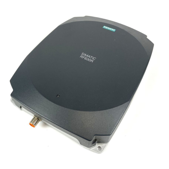
Page 113: Rf630R Reader
SIMATIC S7 controller via an ASM interface module. The degree of protection is IP65. Pos. Description TNCreverse interface for connection of antenna 1 (ANT 1) TNCreverse interface for connection of antenna 2 (ANT 2) LED operating display RS 422 interface (8-pin M12 connector) SIMATIC RF600 System Manual, xx/2014, J31069-D0171-U001-A15-7618... -
Page 114: Ordering Data
Reader is not active, a serious error has occurred. In addition, this LED also indicates the fault status through the number of flashing pulses. Reboot (operating voltage Off → On is necessary). The LED flashes once for the 'INACTIVE' status, rebooting is not necessary in this case. SIMATIC RF600 System Manual, xx/2014, J31069-D0171-U001-A15-7618... -
Page 115: Pin Assignment Of The Rs422 Interface
Earth (shield) The knurled bolt of the M12 plug is not connected to the shield (on the reader side). Note You must therefore not use any SIMATIC connecting cables that use the angled M12 plug. SIMATIC RF600 System Manual, xx/2014, J31069-D0171-U001-A15-7618... -
Page 116: Pin Assignment Of The Connecting Cable
Death or serious injury may occur as a result of lightning strikes to antennas mounted outside buildings. If the reader is operated with antennas mounted outside buildings, it is imperative that the reader is electrically connected to the ground potential. SIMATIC RF600 System Manual, xx/2014, J31069-D0171-U001-A15-7618... -
Page 117: Planning Application
Ground connection Hexagon-head screw Plain washer Cable lug Contact washer: Use contact washers according to the Siemens standard SN 70093-6-FSt-flNnnc- 480h for ground connection, Siemens item No.: H70093-A60-Z3 5.3.2 Planning application 5.3.2.1 Minimum mounting clearances of two antennas of different readers At 500 mW ERP radiated power, due to the opening angle of the antennas, their fields can overlap considerably. -
Page 118: Installing/Mounting
HF radiation, provided that a minimum spacing of 26 cm exists between antenna and person. When the antennas are installed, you must therefore ensure that a minimum spacing of 26 cm is maintained between personnel and antennas. SIMATIC RF600 System Manual, xx/2014, J31069-D0171-U001-A15-7618... -
Page 119: Configuration/Integration
The RF620R reader can alternatively also be connected directly to the PC via the RF182 communication module. For further details on the interface modules used, see Chapter Auto-Hotspot . Further information about commissioning the readers can be found in the Configuration Manual "RF620R/RF630R" in the "Commissioning" section. SIMATIC RF600 System Manual, xx/2014, J31069-D0171-U001-A15-7618... -
Page 120: Transmission Protocols
Color of housing bottom section Silver Status displays on the device 1 LED Colors: red, yellow, green Interfaces Antenna connectors 2 x RTNC plug RS422 1 x plug (8-pin M12) Software SIMATIC S7 MTBF in years 18.2 SIMATIC RF600 System Manual, xx/2014, J31069-D0171-U001-A15-7618... -
Page 121: Simatic Rf600
Radio acc. to R&TTE guidelines, EN 301 489 • • ETSI EN 302-208 V1.1.1 • ETSI EN 302-208 V1.3.1 • ETSI EN 302-208 V1.4.1 • Reader degree of protection acc. to EN 60529 (IP65) • SIMATIC RF600 System Manual, xx/2014, J31069-D0171-U001-A15-7618... -
Page 122: Technical Data According To Epc And Iso
865 ... 867 MHz (10 channels at max. 4 W EIRP) Frequency range Russia 866.1 ... 867.6 MHz (8 channels at 2 W ERP) Frequency range Singapore 866 ... 869 MHz (11 channels at 0.5 W ERP) SIMATIC RF600 System Manual, xx/2014, J31069-D0171-U001-A15-7618... -
Page 123: Maximum Number Of Readable Tags
If you have configured 2 antennas as a gate, both antennas must be turned on at the same time. The reader multiplexes both antennas internally. The multiplexing time is typically 100 ms (internal read time per antenna). SIMATIC RF600 System Manual, xx/2014, J31069-D0171-U001-A15-7618... -
Page 124: Dimension Drawings
Readers 5.3 RF630R reader 5.3.6 Dimension drawings Figure 5-8 Dimension drawing for RF630R All dimensions in mm (± 0.5 mm tolerance) SIMATIC RF600 System Manual, xx/2014, J31069-D0171-U001-A15-7618... -
Page 125: Certificates And Approvals
This product is UL-certified for the USA and Canada. It meets the following safety standard(s): UL 60950-1 - Information Technology Equipment Safety - Part 1: General Requirements CSA C22.2 No. 60950 -1 - Safety of Information Technology Equipment UL Report E 205089 SIMATIC RF600 System Manual, xx/2014, J31069-D0171-U001-A15-7618... -
Page 126: Simatic Rf600
Reader certificate: KCC-CRM-RF5-RF630R H-11409 Argentina radio approval: Registro de la COMISION NACIONAL DE COMUNICACIONES RCPSIRF12-0879 Mexico radio approval: CERTIFICADO DE HOMOLOGACION SIMATIC RF600 System Manual, xx/2014, J31069-D0171-U001-A15-7618... -
Page 127: Fcc Information
Marking on the reader: CMIIT ID: 2012DJ2917 5.3.7.1 FCC information Siemens SIMATIC RF630R (FCC): 6GT2811-4AA00-1AA0, 6GT2811-4AA00-1AA1 FCC ID: NXW-RF630R (for 6GT2811-4AA00-1AA0) FCC ID: NXW-RF600R (for 6GT2811-4AA00-1AA1) This device complies with part 15 of the FCC rules. Operation is subject to the following two... -
Page 128: Ic-Fcb Information
Readers 5.3 RF630R reader 5.3.7.2 IC-FCB information Siemens SIMATIC RF630R (FCC): 6GT2811-4AA00-1AA0, 6GT2811-4AA00-1AA1 IC: 267X-RF630 (for 6GT2811-4AA00-1AA0) IC: 267X-RF600, Model: RF630R-2 (for 6GT2811-4AA00-1AA1) This device complies with Industry Canada licence-exempt RSS standard(s). Operation is subject to the following two conditions:... -
Page 129: Rf640R Reader
PC for parameter assignment. The degree of protection is IP65. Pos. Description TNC reverse interface for connecting an antenna LED operating display 24 VDC power supply Ethernet interface (TCP/IP) Digital I/O interface SIMATIC RF600 System Manual, xx/2014, J31069-D0171-U001-A15-7618... -
Page 130: Ordering Data
Set of protective caps 6GT2898-4AA00 Contains 3 protective caps for antenna output and one protective cap for digital I/O interface (required for IP65 degree of protection when some connectors are unused) RFID DVD "Software & Documentation" 6GT2080-2AA20 SIMATIC RF600 System Manual, xx/2014, J31069-D0171-U001-A15-7618... -
Page 131: Status Display
• Reader or antenna has a defect • Tag is not in the field of radiation of the transmit antenna For more detailed information on the flash codes of the reader see section Flashing codes RF640R/RF670R (Page 479) SIMATIC RF600 System Manual, xx/2014, J31069-D0171-U001-A15-7618... -
Page 132: Pin Assignment Of The Digital I/O Interface
[not electrically isolated]) green DO common yellow DO 0 gray DO 1 pink DI 0 blue DI common DI 1 Knurled ring Shield Knurled ring connected to GND of the reader SIMATIC RF600 System Manual, xx/2014, J31069-D0171-U001-A15-7618... -
Page 133: Connection Scheme For The Digital I/O Interface
Input Inport (0), (1) ● The inputs are optically isolated through optocouplers. ● Level Low 0 ... 3 V; High 3.6 to 24 V ● Sampling rate < 20 ms The following diagrams illustrate various connection possibilities. SIMATIC RF600 System Manual, xx/2014, J31069-D0171-U001-A15-7618... -
Page 134: Simatic Rf600
Voltage infeed through internal source (no electrical isolation) Figure 5-10 Example circuit 1: Digital inputs Alternative connection possibilities: ● Pin 2 (VCC) to Pin 9 DI Common ● Pin 1 GND to busbar inputs SIMATIC RF600 System Manual, xx/2014, J31069-D0171-U001-A15-7618... -
Page 135: Simatic Rf600
Readers 5.4 RF640R reader Voltage infeed through external source Figure 5-11 Example circuit 2: Digital inputs Voltage infeed through external source with various voltages Figure 5-12 Example circuit 3: Digital inputs SIMATIC RF600 System Manual, xx/2014, J31069-D0171-U001-A15-7618... -
Page 136: Simatic Rf600
5.4 RF640R reader Voltage infeed through internal source Figure 5-13 Example circuit 4: Digital outputs Alternative connection possibilities: ● Pin 1 GND to Pin 3 DO Common ● Pin 2 (VCC) to busbar outputs SIMATIC RF600 System Manual, xx/2014, J31069-D0171-U001-A15-7618... -
Page 137: Simatic Rf600
5.4 RF640R reader Voltage infeed through external source Figure 5-14 Example circuit 5: Digital outputs Voltage infeed through an external source is shown here for 12°V by way of example. Other voltages are also permissible. SIMATIC RF600 System Manual, xx/2014, J31069-D0171-U001-A15-7618... -
Page 138: Pin Assignment For Power Supply
Power connector (on reader side) Pin assignment 24 VDC Not connected Ground (0 V) Not connected The power connector of the RF640R is conforms with the PNO standard, in other words, normal PROFINET IO connectors fit this interface. SIMATIC RF600 System Manual, xx/2014, J31069-D0171-U001-A15-7618... -
Page 139: Pin Assignment For Industrial Ethernet Interface
Terminated Note We recommend that only original Siemens Ethernet crossover cables are used (10 m cable: Order No. 6GT2891-1HN10) or the Siemens connector (see Section Ordering data (Page 130)) for connecting to the Ethernet socket of the reader. If plug-in connectors from... -
Page 140: Planning The Use
5.4 RF640R reader Ground connection Hexagon-head screw Plain washer Cable lug Contact washer: Use contact washers according to the Siemens standard SN 70093-6-FSt-flNnnc- 480h for ground connection, Siemens item No.: H70093-A60-Z3 5.4.2 Planning the use 5.4.2.1 Selecting the antenna With the SIMATIC RF640R, there are two ways of using the antenna that are mutually exclusive: ●... -
Page 141: Simatic Rf600
(Azimuth section) as well as the horizontal plane (elevation section) must be considered. This results in a spatial image of the directional radiation pattern of the antenna with its main and auxiliary fields. SIMATIC RF600 System Manual, xx/2014, J31069-D0171-U001-A15-7618... -
Page 142: Simatic Rf600
Radiation diagram (Azimuth section) Vertical component of the polarization direction of the antenna Horizontal component of the polarization direction of the antenna Right circular component of the polarization direction of the antenna Figure 5-16 Azimuth section SIMATIC RF600 System Manual, xx/2014, J31069-D0171-U001-A15-7618... -
Page 143: Simatic Rf600
Radiation diagram (elevation section) Vertical component of the polarization direction of the antenna Horizontal component of the polarization direction of the antenna Right circular component of the polarization direction of the antenna Figure 5-17 Elevation section SIMATIC RF600 System Manual, xx/2014, J31069-D0171-U001-A15-7618... -
Page 144: Simatic Rf600
(Azimuth section) as well as the horizontal plane (elevation section) must be considered. This results in a spatial image of the directional radiation pattern of the antenna with its main and auxiliary fields. Azimuth XZ plane Elevation YZ plane SIMATIC RF600 System Manual, xx/2014, J31069-D0171-U001-A15-7618... -
Page 145: Simatic Rf600
Radiation diagram (Azimuth section) Vertical component of the polarization direction of the antenna Horizontal component of the polarization direction of the antenna Right circular component of the polarization direction of the antenna Figure 5-18 Azimuth section SIMATIC RF600 System Manual, xx/2014, J31069-D0171-U001-A15-7618... -
Page 146: Simatic Rf600
Radiation diagram (elevation section) Vertical component of the polarization direction of the antenna Horizontal component of the polarization direction of the antenna Right circular component of the polarization direction of the antenna Figure 5-19 Elevation section SIMATIC RF600 System Manual, xx/2014, J31069-D0171-U001-A15-7618... -
Page 147: Simatic Rf600
Antenna/read point configurations The RF640R reader has an internal circular polarized antenna. You can cover one read point with this antenna. When several RF640R readers are used, the readers are addressed via the SIMATIC level. SIMATIC RF600 System Manual, xx/2014, J31069-D0171-U001-A15-7618... -
Page 148: External Antenna
● Via a standardized VESA 100 mounting system using the Antenna Mounting Kit (see section Mounting with antenna mounting kit (Page 331)). Tighten the M4 screws on the rear of the reader using a maximum torque of ≤ 1.3 Nm. ● Directly onto a flat surface. SIMATIC RF600 System Manual, xx/2014, J31069-D0171-U001-A15-7618... -
Page 149: Configuration/Integration
XML commands. Simple process controls (e.g. signal lights) can be directly implemented using the write/read device via two digital inputs and outputs. Figure 5-20 Overview of configuration of the RF640R reader SIMATIC RF600 System Manual, xx/2014, J31069-D0171-U001-A15-7618... -
Page 150: Technical Data
19 s All supply and signal voltages must be safety extra low voltage (SELV/PELV according to EN 60950) 24 VDC supply: safe (electrical) isolation of extra-low voltage (SELV / PELV acc. to EN 60950) SIMATIC RF600 System Manual, xx/2014, J31069-D0171-U001-A15-7618... -
Page 151: Simatic Rf600
IEC60950, including US and Canadian variants of it • Reader degree of protection acc. to EN 60529 (IP65) • FCC CFR47 Part 15.247 • RoHS-compliant according to EU Directive 2002/95/EC • Industrial Canada, RSS-210, Issue 7, June 2007 • SIMATIC RF600 System Manual, xx/2014, J31069-D0171-U001-A15-7618... -
Page 152: Technical Data According To Epc And Iso
Frequency range Brazil 915.125 ... 927.875 MHz (52 channels at max. 4 W EIRP, frequency hopping) Frequency range South Korea 917.1 ... 920.4 MHz (7-16 channels at max. 4 W EIRP, frequency hopping) SIMATIC RF600 System Manual, xx/2014, J31069-D0171-U001-A15-7618... -
Page 153: Dimension Drawings
5.4 RF640R reader CMIIT frequencies Frequency range China 920.625 ... 924.375 MHz (16 subchannels at 2 W ERP) 5.4.6 Dimension drawings Figure 5-21 Dimensional drawing of RF640R All dimensions in mm (± 0.5 mm tolerance) SIMATIC RF600 System Manual, xx/2014, J31069-D0171-U001-A15-7618... -
Page 154: Certificates And Approvals
This product is UL-certified for the USA and Canada. It meets the following safety standard(s): UL 60950-1 - Information Technology Equipment Safety - Part 1: General Requirements CSA C22.2 No. 60950 -1 - Safety of Information Technology Equipment UL Report E 205089 SIMATIC RF600 System Manual, xx/2014, J31069-D0171-U001-A15-7618... -
Page 155: Simatic Rf600
Argentina radio approval: Registro de la COMISION NACIONAL DE COMUNICACIONES RCPSIRF12-0880 Mexico radio approval: CERTIFICADO DE HOMOLOGACION Table 5- 18 6GT2811-3BA00-2AA1 Standard CMIIT Certification China radio approval Marking on the reader: CMIIT ID: 2012DJ2918 SIMATIC RF600 System Manual, xx/2014, J31069-D0171-U001-A15-7618... -
Page 156: Fcc Information
Readers 5.4 RF640R reader 5.4.7.1 FCC information Siemens SIMATIC RF640R (FCC): 6GT2811-3BA00-1AA0 FCC ID: NXW-RF600R This device complies with part 15 of the FCC rules. Operation is subject to the following two conditions: (1) This device may not cause harmful interference, and (2) this device must accept any interference received, including interference that may cause undesired operation. -
Page 157: Ic-Fcb Information
Readers 5.4 RF640R reader 5.4.7.2 IC-FCB information Siemens SIMATIC RF640R (FCC): 6GT2811-3BA00-1AA0 IC: 267X-RF600R, Model RF640R This device complies with Industry Canada licence-exempt RSS standard(s). Operation is subject to the following two conditions: (1) This device may not cause interference, and (2) this device must accept any interference, including interference that may cause undesired operation of the device. -
Page 158: Rf650R Reader
Ordering data Ordering data RF650R Product Article number RF650R (ETSI) reader basic unit for EU, EFTA, Turkey 6GT2811-6AB20-0AA0 RF650R (FCC) reader basic unit for the USA 6GT2811-6AB20-1AA0 RF650R (CMIIT) reader basic unit for China 6GT2811-6AB20-2AA0 SIMATIC RF600 System Manual, xx/2014, J31069-D0171-U001-A15-7618... -
Page 159: Simatic Rf600
Set of protective caps 6GT2898-4AA00 Contains 3 protective caps for antenna output and one protective cap for digital I/O interface (required for IP65 degree of protection when some connectors are unused) RFID DVD "Software & Documentation" 6GT2080-2AA20 SIMATIC RF600 System Manual, xx/2014, J31069-D0171-U001-A15-7618... -
Page 160: Status Display
DO 2 / Outport 02 DO 3 / Outport 03 DI 0 / Inport 00 DI Common / Inport Common DI 1 / Inport 01 DI 2 / Inport 02 DI 3 / Inport 03 SIMATIC RF600 System Manual, xx/2014, J31069-D0171-U001-A15-7618... -
Page 161: Connection Scheme For The Digital I/O Interface
Input Inport (0), (1), (2), (3) ● The inputs are optically isolated through optocouplers. ● Level Low 0 ... 3 V; High 3.6 ... 24 V ● Sampling rate < 20 ms The following diagrams illustrate various connection possibilities. SIMATIC RF600 System Manual, xx/2014, J31069-D0171-U001-A15-7618... -
Page 162: Simatic Rf600
Voltage infeed from internal source (no electrical isolation) Figure 5-23 Circuit example 1: Digital inputs Alternative connection possibilities: ● Pin 2 (VCC) to Pin 9 DI Common ● Pin 1 GND to busbar inputs SIMATIC RF600 System Manual, xx/2014, J31069-D0171-U001-A15-7618... -
Page 163: Simatic Rf600
Readers 5.5 RF650R reader Voltage infeed from external source Figure 5-24 Circuit example 2: Digital inputs Voltage infeed from external source with various voltages Figure 5-25 Circuit example 3: Digital inputs SIMATIC RF600 System Manual, xx/2014, J31069-D0171-U001-A15-7618... -
Page 164: Simatic Rf600
5.5 RF650R reader Voltage infeed from internal source Figure 5-26 Circuit example 4: Digital outputs Alternative connection possibilities: ● Pin 1 GND to Pin 3 DO Common ● Pin 2 (VCC) to busbar outputs SIMATIC RF600 System Manual, xx/2014, J31069-D0171-U001-A15-7618... -
Page 165: Simatic Rf600
5.5 RF650R reader Voltage infeed from external source Figure 5-27 Circuit example 5: Digital outputs Voltage infeed from an external source is shown here for 12°V by way of example. Other voltages are also permissible. SIMATIC RF600 System Manual, xx/2014, J31069-D0171-U001-A15-7618... -
Page 166: Simatic Rf600
Readers 5.5 RF650R reader Voltage infeed from external source with various voltages Figure 5-28 Circuit example 6: Digital outputs SIMATIC RF600 System Manual, xx/2014, J31069-D0171-U001-A15-7618... -
Page 167: Pin Assignment Of The Rs-422 Interface
Terminated Note We recommend that only original Siemens Ethernet crossover cables are used (10 m cable: Article number 6GT2891-1HN10) or the Siemens plug (refer to the section Ordering data (Page 158)) for connecting to the Ethernet socket of the reader. If plug-in connectors from other manufacturers are used, it may be difficult or even impossible to remove the plug from the reader. -
Page 168: Grounding Connection
VDE 0182 or IEC 62305 standards. Ground connection Hexagon-head screw Flat washer Cable lug Contact washer: Use contact washers according to the Siemens standard SN 70093-6-FSt-flNnnc- 480h for ground connection, Siemens item no.: H70093-A60-Z3 SIMATIC RF600 System Manual, xx/2014, J31069-D0171-U001-A15-7618... -
Page 169: Planning Operation
HF radiation, provided that a minimum spacing of 26 cm exists between antenna and person. When the antennas are installed, you must therefore ensure that a minimum spacing of 26 cm is maintained between personnel and antennas. SIMATIC RF600 System Manual, xx/2014, J31069-D0171-U001-A15-7618... -
Page 170: Configuration/Integration
XML commands. Simple process controls (e.g. a traffic signal) can be implemented directly using the write/read device via four digital inputs and outputs. Figure 5-29 Overview of configuration of the RF650R reader SIMATIC RF600 System Manual, xx/2014, J31069-D0171-U001-A15-7618... -
Page 171: Technical Specifications
20 V input voltage on the reader (typical) • 370 mA / 8.9 W 24 V input voltage on the reader (typical) • 300 mA / 9.0 W 30 V input voltage on the reader (typical) • SIMATIC RF600 System Manual, xx/2014, J31069-D0171-U001-A15-7618... -
Page 172: Simatic Rf600
≤ 1 W • • ≤ 1 W • • Reading range Antennas mounted on opposing sides (portal max. 10 m configuration) Antennas mounted on the same side max. 5 m (dependent on transponder) SIMATIC RF600 System Manual, xx/2014, J31069-D0171-U001-A15-7618... -
Page 173: Dimension Drawing
(50 channels at max. 4 W ERP, frequency hopping) CMIIT frequencies Frequency range China 920.625 ... 924.375 MHz (16 subchannels at 2 W ERP) 5.5.6 Dimension drawing Figure 5-30 Dimension drawing RF650R All dimensions in mm (± 0.5 mm tolerance) SIMATIC RF600 System Manual, xx/2014, J31069-D0171-U001-A15-7618... -
Page 174: Certificates And Approvals
General Requirements CSA C22.2 No. 60950 -1 - Safety of Information Technology Equipment UL Report E 205089 Table 5- 24 6GT2811-6AB20-2AA0 Standard CMIIT Certification China radio approval Marking on the reader: CMIIT ID: ?????? SIMATIC RF600 System Manual, xx/2014, J31069-D0171-U001-A15-7618... -
Page 175: Fcc Information
Readers 5.5 RF650R reader 5.5.7.1 FCC information Siemens SIMATIC RF650R (FCC): 6GT2811-6AB20-1AA0 FCC ID: This device complies with part 15 of the FCC rules. Operation is subject to the following two conditions: (1) This device may not cause harmful interference, and (2) this device must accept any interference received, including interference that may cause undesired operation. -
Page 176: Ic-Fcb Information
Readers 5.5 RF650R reader 5.5.7.2 IC-FCB information Siemens SIMATIC RF650R (FCC): 6GT2811-6AB20-1AA0 This device complies with Industry Canada licence-exempt RSS standard(s). Operation is subject to the following two conditions: (1) This device may not cause interference, and (2) this device must accept any interference, including interference that may cause undesired operation of the device. -
Page 177: Rf670R Reader
PC for parameter assignment. The degree of protection is IP65. Pos. Description TNC reverse interfaces for connecting up to four antennas LED operating display 24 VDC power supply Ethernet interface (TCP/IP) Digital I/O interface SIMATIC RF600 System Manual, xx/2014, J31069-D0171-U001-A15-7618... -
Page 178: Ordering Data
Set of protective caps 6GT2898-4AA00 Contains 3 protective caps for antenna output and one protective cap for digital I/O interface (required for IP65 degree of protection when some connectors are unused) RFID DVD "Software & Documentation" 6GT2080-2AA20 SIMATIC RF600 System Manual, xx/2014, J31069-D0171-U001-A15-7618... -
Page 179: Status Display
• Reader or antenna has a defect • Tag is not in the field of radiation of the transmit antenna For more detailed information on the flash codes of the reader see section Flashing codes RF640R/RF670R (Page 479) SIMATIC RF600 System Manual, xx/2014, J31069-D0171-U001-A15-7618... -
Page 180: Pin Assignment Of The Digital I/O Interface
Wiring diagram M12 connector (cable end) You will need to assemble your reader cable with a suitable connector that fits the interface shown above. Keep to the following wiring diagram: Figure 5-31 M12 connector wiring diagram SIMATIC RF600 System Manual, xx/2014, J31069-D0171-U001-A15-7618... -
Page 181: Connection Scheme For The Digital I/O Interface
● Level Low 0 ... 3 V; High 3,6 ... 24 V ● Sampling rate < 20 ms The following diagrams illustrate various connection possibilities. Voltage infeed through internal source (no electrical isolation) Figure 5-32 Example circuit 1: Digital inputs SIMATIC RF600 System Manual, xx/2014, J31069-D0171-U001-A15-7618... -
Page 182: Simatic Rf600
5.6 RF670R reader Alternative connection possibilities: ● Pin 2 (VCC) to Pin 9 DI Common ● Pin 1 GND to busbar inputs Voltage infeed through external source Figure 5-33 Example circuit 2: Digital inputs SIMATIC RF600 System Manual, xx/2014, J31069-D0171-U001-A15-7618... -
Page 183: Simatic Rf600
Readers 5.6 RF670R reader Voltage infeed through external source with various voltages Figure 5-34 Example circuit 3: Digital inputs Voltage infeed through internal source Figure 5-35 Example circuit 4: Digital outputs SIMATIC RF600 System Manual, xx/2014, J31069-D0171-U001-A15-7618... -
Page 184: Simatic Rf600
● Pin 2 (VCC) to busbar outputs Voltage infeed through external source Figure 5-36 Example circuit 5: Digital outputs Voltage infeed through an external source is shown here for 12°V by way of example. Other voltages are also permissible. SIMATIC RF600 System Manual, xx/2014, J31069-D0171-U001-A15-7618... -
Page 185: Pin Assignment For Power Supply
Power connector (on reader side) Pin assignment 24 VDC Not connected Ground (0 V) Not connected The power connector of the RF670R is PNO compatible, i.e.° normal PROFINET IO connectors will fit this interface. SIMATIC RF600 System Manual, xx/2014, J31069-D0171-U001-A15-7618... -
Page 186: Pin Assignment For Industrial Ethernet Interface
Terminated Note We recommend that only original Siemens Ethernet crossover cables are used (10 m cable: Order No. 6GT2891-1HN10) or the Siemens connector (see Section Ordering data (Page 178)) for connecting to the Ethernet socket of the reader. If plug-in connectors from... -
Page 187: Planning The Use
5.6 RF670R reader Ground connection Hexagon-head screw Plain washer Cable lug Contact washer: Use contact washers according to the Siemens standard SN 70093-6-FSt-flNnnc- 480h for ground connection, Siemens item No.: H70093-A60-Z3 5.6.2 Planning the use 5.6.2.1 Antenna/read point configurations You can connect up to four external antennas to the RF670R reader. The standard setting is that four antennas are connected when the reader is started. -
Page 188: Installing / Mounting
≤ 1.3 Nm. ● Directly onto a flat surface. The positions of the fixing holes for the device are shown in the section Dimension drawings (Page 193). SIMATIC RF600 System Manual, xx/2014, J31069-D0171-U001-A15-7618... -
Page 189: Configuration/Integration
XML commands. Simple process controls (e.g. a traffic signal) can be implemented directly using the write/read device via four digital inputs and outputs. Figure 5-38 Overview of configuration of the RF670R reader SIMATIC RF600 System Manual, xx/2014, J31069-D0171-U001-A15-7618... -
Page 190: Technical Data
19 s All supply and signal voltages must be safety extra low voltage (SELV/PELV according to EN 60950) 24 VDC supply: safe (electrical) isolation of extra-low voltage (SELV / PELV acc. to EN 60950) SIMATIC RF600 System Manual, xx/2014, J31069-D0171-U001-A15-7618... -
Page 191: Simatic Rf600
IEC60950, including US and Canadian variants of it • Reader degree of protection acc. to EN 60529 (IP65) • FCC CFR47 Part 15.247 • RoHS-compliant according to EU Directive 2002/95/EC • Industrial Canada, RSS-210, Issue 7, June 2007 • SIMATIC RF600 System Manual, xx/2014, J31069-D0171-U001-A15-7618... -
Page 192: Technical Data According To Epc And Iso
Frequency range South Korea 917.1 ... 920.4 MHz (7-16 channels at max. 4 W EIRP, frequency hopping) CMIIT frequencies Frequency range China 920.625 ... 924.375 MHz (16 subchannels at 2 W ERP) SIMATIC RF600 System Manual, xx/2014, J31069-D0171-U001-A15-7618... -
Page 193: Dimension Drawings
Readers 5.6 RF670R reader 5.6.6 Dimension drawings Figure 5-39 Dimension drawing for RF670R All dimensions in mm (± 0.5 mm tolerance) SIMATIC RF600 System Manual, xx/2014, J31069-D0171-U001-A15-7618... -
Page 194: Certificates And Approvals
This product is UL-certified for the USA and Canada. It meets the following safety standard(s): UL 60950-1 - Information Technology Equipment Safety - Part 1: General Requirements CSA C22.2 No. 60950 -1 - Safety of Information Technology Equipment UL Report E 205089 SIMATIC RF600 System Manual, xx/2014, J31069-D0171-U001-A15-7618... -
Page 195: Simatic Rf600
Reader certificate: KCC-CRM-RF5-RF670R H-11390 Argentina radio approval: Registro de la COMISION NACIONAL DE COMUNICACIONES RCPSIRF12-0881 Mexico radio approval: CERTIFICADO DE HOMOLOGACION SIMATIC RF600 System Manual, xx/2014, J31069-D0171-U001-A15-7618... -
Page 196: Fcc Information
Marking on the reader: CMIIT ID: 2011DJ0748 5.6.7.1 FCC information Siemens SIMATIC RF670R (FCC): 6GT2811-0AB00-1AA0 FCC ID: NXW-RF670 (as of FS: A1) FCC ID: NXW-RF600R (as of FS: C1) This device complies with part 15 of the FCC rules. Operation is subject to the following two... -
Page 197: Ic-Fcb Information
Readers 5.6 RF670R reader 5.6.7.2 IC-FCB information Siemens SIMATIC RF670R (FCC): 6GT2811-0AB00-1AA0 IC: 267X-RF670 (as of FS: A1) IC: NXW-RF600R, model: RF670R-2 (as of FS: C1) This device complies with Industry Canada licence-exempt RSS standard(s). Operation is subject to the following two conditions:... -
Page 198: Rf680R Reader
Ordering data Ordering data RF680R Product Article number RF680R (ETSI) reader basic unit for EU, EFTA, Turkey 6GT2811-6AA10-0AA0 RF680R (FCC) reader basic unit for the USA 6GT2811-6AA10-1AA0 RF680R (CMIIT) reader basic unit for China 6GT2811-6AA10-2AA0 SIMATIC RF600 System Manual, xx/2014, J31069-D0171-U001-A15-7618... -
Page 199: Simatic Rf600
Set of protective caps 6GT2898-4AA00 Contains 3 protective caps for antenna output and one protective cap for digital I/O interface (required for IP65 degree of protection when some connectors are unused) RFID DVD "Software & Documentation" 6GT2080-2AA20 SIMATIC RF600 System Manual, xx/2014, J31069-D0171-U001-A15-7618... -
Page 200: Status Display
DO 2 / Outport 02 DO 3 / Outport 03 DI 0 / Inport 00 DI Common / Inport Common DI 1 / Inport 01 DI 2 / Inport 02 DI 3 / Inport 03 SIMATIC RF600 System Manual, xx/2014, J31069-D0171-U001-A15-7618... -
Page 201: Connection Scheme For The Digital I/O Interface
Input Inport (0), (1), (2), (3) ● The inputs are optically isolated through optocouplers. ● Level Low 0 ... 3 V; High 3.6 ... 24 V ● Sampling rate < 20 ms The following diagrams illustrate various connection possibilities. SIMATIC RF600 System Manual, xx/2014, J31069-D0171-U001-A15-7618... -
Page 202: Simatic Rf600
Voltage infeed from internal source (no electrical isolation) Figure 5-41 Circuit example 1: Digital inputs Alternative connection possibilities: ● Pin 2 (VCC) to pin 9 DI common ● Pin 1 GND to busbar inputs SIMATIC RF600 System Manual, xx/2014, J31069-D0171-U001-A15-7618... -
Page 203: Simatic Rf600
Readers 5.7 RF680R reader Voltage infeed from external source Figure 5-42 Circuit example 2: Digital inputs Voltage infeed from external source with various voltages Figure 5-43 Circuit example 3: Digital inputs SIMATIC RF600 System Manual, xx/2014, J31069-D0171-U001-A15-7618... -
Page 204: Simatic Rf600
5.7 RF680R reader Voltage infeed from internal source Figure 5-44 Circuit example 4: Digital outputs Alternative connection possibilities: ● Pin 1 GND to pin 3 DO common ● Pin 2 (VCC) to busbar outputs SIMATIC RF600 System Manual, xx/2014, J31069-D0171-U001-A15-7618... -
Page 205: Simatic Rf600
5.7 RF680R reader Voltage infeed from external source Figure 5-45 Circuit example 5: Digital outputs Voltage infeed from an external source is shown here for 12°V as an example. Other voltages are also permissible. SIMATIC RF600 System Manual, xx/2014, J31069-D0171-U001-A15-7618... -
Page 206: Simatic Rf600
Readers 5.7 RF680R reader Voltage infeed from external source with various voltages Figure 5-46 Circuit example 6: Digital outputs SIMATIC RF600 System Manual, xx/2014, J31069-D0171-U001-A15-7618... -
Page 207: Pin Assignment Of The Rs-422 Interface
Death or serious injury may occur as a result of lightning strikes to antennas mounted outside buildings. If the reader is operated with antennas mounted outside buildings, it is imperative that the reader is electrically connected to the ground potential. SIMATIC RF600 System Manual, xx/2014, J31069-D0171-U001-A15-7618... -
Page 208: Planning Operation
Ground connection Hexagon-head screw Flat washer Cable lug Contact washer: Use contact washers according to the Siemens standard SN 70093-6-FSt-flNnnc- 480h for ground connection, Siemens item no.: H70093-A60-Z3 5.7.2 Planning operation 5.7.2.1 Antenna/read point configurations You can connect up to four external antennas to the RF680R reader. The standard setting is that four antennas are connected when the reader is started. -
Page 209: Installation/Mounting
≤ 1.3 Nm. ● Directly on a flat surface. The positions of the mounting holes for the device are shown in the section Dimension drawing (Page 213). SIMATIC RF600 System Manual, xx/2014, J31069-D0171-U001-A15-7618... -
Page 210: Configuration/Integration
XML commands. Simple process controls (e.g. a traffic signal) can be implemented directly using the write/read device via four digital inputs and outputs. Figure 5-47 Overview of configuration of the RF680R reader SIMATIC RF600 System Manual, xx/2014, J31069-D0171-U001-A15-7618... -
Page 211: Technical Specifications
20 V input voltage on the reader (typical) • 380 mA / 9.1 W 24 V input voltage on the reader (typical) • 300 mA / 9.6 W 30 V input voltage on the reader (typical) • SIMATIC RF600 System Manual, xx/2014, J31069-D0171-U001-A15-7618... -
Page 212: Simatic Rf600
≤ 2 W • • ≤ 2 W • • Reading range Antennas mounted on opposing sides (portal max. 10 m configuration) Antennas mounted on the same side max. 5 m (dependent on transponder) SIMATIC RF600 System Manual, xx/2014, J31069-D0171-U001-A15-7618... -
Page 213: Dimension Drawing
(50 channels at max. 4 W EIRP, frequency hopping) CMIIT frequencies Frequency band China 920,625 ... 924.375 MHz (16 subchannels at 2 W ERP) 5.7.6 Dimension drawing Figure 5-48 Dimension drawing RF680R All dimensions in mm (± 0.5 mm tolerance) SIMATIC RF600 System Manual, xx/2014, J31069-D0171-U001-A15-7618... -
Page 214: Certificates And Approvals
General Requirements CSA C22.2 No. 60950 -1 - Safety of Information Technology Equipment UL Report E 205089 Table 5- 34 6GT2811-6AA10-2AA0 Standard CMIIT Certification China radio approval Marking on the reader: CMIIT ID: ?????? SIMATIC RF600 System Manual, xx/2014, J31069-D0171-U001-A15-7618... -
Page 215: Fcc Information
Readers 5.7 RF680R reader 5.7.7.1 FCC information Siemens SIMATIC RF680R (FCC): 6GT2811-6AA10-1AA0 FCC ID: This device complies with part 15 of the FCC rules. Operation is subject to the following two conditions: (1) This device may not cause harmful interference, and (2) this device must accept any interference received, including interference that may cause undesired operation. -
Page 216: Ic-Fcb Information
Readers 5.7 RF680R reader 5.7.7.2 IC-FCB information Siemens SIMATIC RF680R (FCC): 6GT2811-6AA10-1AA0 This device complies with Industry Canada licence-exempt RSS standard(s). Operation is subject to the following two conditions: (1) This device may not cause interference, and (2) this device must accept any interference, including interference that may cause undesired operation of the device. -
Page 217: Rf685R Reader
② LED status display ③ LED operating display ④ Digital I/O interface ⑤ RS-422 interface (M12 plug, 8-pin) ⑥ Ethernet interface (TCP/IP) (M12 plug, 4-pin) ⑦ Ethernet interface (TCP/IP) (M12 plug, 4-pin) SIMATIC RF600 System Manual, xx/2014, J31069-D0171-U001-A15-7618... -
Page 218: Ordering Data
Set of protective caps 6GT2898-4AA00 Contains 3 protective caps for antenna output and one protective cap for digital I/O interface (required for IP65 degree of protection when some connectors are unused) RFID DVD "Software & Documentation" 6GT2080-2AA20 SIMATIC RF600 System Manual, xx/2014, J31069-D0171-U001-A15-7618... -
Page 219: Status Display
DO 2 / Outport 02 DO 3 / Outport 03 DI 0 / Inport 00 DI Common / Inport Common DI 1 / Inport 01 DI 2 / Inport 02 DI 3 / Inport 03 SIMATIC RF600 System Manual, xx/2014, J31069-D0171-U001-A15-7618... -
Page 220: Connection Scheme For The Digital I/O Interface
Input Inport (0), (1), (2), (3) ● The inputs are optically isolated through optocouplers. ● Level Low 0 ... 3 V; High 3.6 ... 24 V ● Sampling rate < 20 ms The following diagrams illustrate various connection possibilities. SIMATIC RF600 System Manual, xx/2014, J31069-D0171-U001-A15-7618... -
Page 221: Simatic Rf600
Voltage infeed from internal source (no electrical isolation) Figure 5-50 Circuit example 1: Digital inputs Alternative connection possibilities: ● Pin 2 (VCC) to pin 9 DI common ● Pin 1 GND to busbar inputs SIMATIC RF600 System Manual, xx/2014, J31069-D0171-U001-A15-7618... -
Page 222: Simatic Rf600
Readers 5.8 RF685R reader Voltage infeed from external source Figure 5-51 Circuit example 2: Digital inputs Voltage infeed from external source with various voltages Figure 5-52 Circuit example 3: Digital inputs SIMATIC RF600 System Manual, xx/2014, J31069-D0171-U001-A15-7618... -
Page 223: Simatic Rf600
5.8 RF685R reader Voltage infeed from internal source Figure 5-53 Circuit example 4: Digital outputs Alternative connection possibilities: ● Pin 1 GND to pin 3 DO common ● Pin 2 (VCC) to busbar outputs SIMATIC RF600 System Manual, xx/2014, J31069-D0171-U001-A15-7618... -
Page 224: Simatic Rf600
5.8 RF685R reader Voltage infeed from external source Figure 5-54 Circuit example 5: Digital outputs Voltage infeed from an external source is shown here for 12°V as an example. Other voltages are also permissible. SIMATIC RF600 System Manual, xx/2014, J31069-D0171-U001-A15-7618... -
Page 225: Simatic Rf600
Readers 5.8 RF685R reader Voltage infeed from external source with various voltages Figure 5-55 Circuit example 6: Digital outputs SIMATIC RF600 System Manual, xx/2014, J31069-D0171-U001-A15-7618... -
Page 226: Pin Assignment Of The Rs-422 Interface
Death or serious injury may occur as a result of lightning strikes to antennas mounted outside buildings. If the reader is operated with antennas mounted outside buildings, it is imperative that the reader is electrically connected to the ground potential. SIMATIC RF600 System Manual, xx/2014, J31069-D0171-U001-A15-7618... -
Page 227: Planning Operation
Ground connection Hexagon-head screw Flat washer Cable lug Contact washer: Use contact washers according to the Siemens standard SN 70093-6-FSt-flNnnc- 480h for ground connection, Siemens item no.: H70093-A60-Z3 5.8.2 Planning operation 5.8.2.1 Selecting the antenna With the SIMATIC RF685R, there are two ways of using the antenna that are mutually exclusive: ●... -
Page 228: Simatic Rf600
(azimuth section) as well as the horizontal plane (elevation section) must be considered. This results in a spatial image of the directional radiation pattern of the antenna with its main and secondary fields. SIMATIC RF600 System Manual, xx/2014, J31069-D0171-U001-A15-7618... -
Page 229: Simatic Rf600
Radiation diagram (Azimuth section) Vertical component of the polarization direction of the antenna Horizontal component of the polarization direction of the antenna Right circular component of the polarization direction of the antenna Figure 5-56 Azimuth section SIMATIC RF600 System Manual, xx/2014, J31069-D0171-U001-A15-7618... -
Page 230: Simatic Rf600
Radiation diagram (elevation section) Vertical component of the polarization direction of the antenna Horizontal component of the polarization direction of the antenna Right circular component of the polarization direction of the antenna Figure 5-57 Elevation section SIMATIC RF600 System Manual, xx/2014, J31069-D0171-U001-A15-7618... -
Page 231: Simatic Rf600
(azimuth section) as well as the horizontal plane (elevation section) must be considered. This results in a spatial image of the directional radiation pattern of the antenna with its main and secondary fields. Azimuth XZ plane Elevation YZ plane SIMATIC RF600 System Manual, xx/2014, J31069-D0171-U001-A15-7618... -
Page 232: Simatic Rf600
Radiation diagram (Azimuth section) Vertical component of the polarization direction of the antenna Horizontal component of the polarization direction of the antenna Right circular component of the polarization direction of the antenna Figure 5-58 Azimuth section SIMATIC RF600 System Manual, xx/2014, J31069-D0171-U001-A15-7618... -
Page 233: Simatic Rf600
Radiation diagram (elevation section) Vertical component of the polarization direction of the antenna Horizontal component of the polarization direction of the antenna Right circular component of the polarization direction of the antenna Figure 5-59 Elevation section SIMATIC RF600 System Manual, xx/2014, J31069-D0171-U001-A15-7618... -
Page 234: Simatic Rf600
The RF685R reader has a switchable antenna (circular or linear polarization). You can cover one read point with this antenna. When several RF685R readers are used, the readers are addressed via the SIMATIC level. SIMATIC RF600 System Manual, xx/2014, J31069-D0171-U001-A15-7618... -
Page 235: External Antenna
● Via a standardized VESA 100 mounting system using the Antenna Mounting Kit (refer to the section Mounting with antenna mounting kit (Page 331)). Tighten the M4 screws on the rear of the reader using a maximum torque of ≤ 1.3 Nm. ● Directly on a flat surface. SIMATIC RF600 System Manual, xx/2014, J31069-D0171-U001-A15-7618... -
Page 236: Configuration/Integration
XML commands. Simple process controls (e.g. a traffic signal) can be implemented directly using the write/read device via four digital inputs and outputs. Figure 5-60 Overview of configuration of the RF685R reader SIMATIC RF600 System Manual, xx/2014, J31069-D0171-U001-A15-7618... -
Page 237: Technical Specifications
20 V input voltage on the reader (typical) • 380 mA / 9.1 W 24 V input voltage on the reader (typical) • 300 mA / 9.6 W 30 V input voltage on the reader (typical) • SIMATIC RF600 System Manual, xx/2014, J31069-D0171-U001-A15-7618... -
Page 238: Simatic Rf600
≤ 2 W • • ≤ 2 W • • Reading range Antennas mounted on opposing sides (portal max. 10 m configuration) Antennas mounted on the same side max. 5 m (dependent on transponder) SIMATIC RF600 System Manual, xx/2014, J31069-D0171-U001-A15-7618... -
Page 239: Dimension Drawing
(50 channels at max. 4 W EIRP, frequency hopping) CMIIT frequencies Frequency band China 920,625 ... 924.375 MHz (16 subchannels at 2 W ERP) 5.8.6 Dimension drawing Figure 5-61 Dimension drawing RF685R All dimensions in mm (± 0.5 mm tolerance) SIMATIC RF600 System Manual, xx/2014, J31069-D0171-U001-A15-7618... -
Page 240: Certificates And Approvals
General Requirements CSA C22.2 No. 60950 -1 - Safety of Information Technology Equipment UL Report E 205089 Table 5- 42 6GT2811-6CA10-2AA0 Standard CMIIT Certification China radio approval Marking on the reader: CMIIT ID: ?????? SIMATIC RF600 System Manual, xx/2014, J31069-D0171-U001-A15-7618... -
Page 241: Fcc Information
Readers 5.8 RF685R reader 5.8.7.3 FCC information Siemens SIMATIC RF685R (FCC): 6GT2811-6CA10-1AA0 FCC ID: This device complies with part 15 of the FCC rules. Operation is subject to the following two conditions: (1) This device may not cause harmful interference, and (2) this device must accept any interference received, including interference that may cause undesired operation. -
Page 242: Ic-Fcb Information
Readers 5.8 RF685R reader 5.8.7.4 IC-FCB information Siemens SIMATIC RF685R (FCC): 6GT2811-6CA10-1AA0 This device complies with Industry Canada licence-exempt RSS standard(s). Operation is subject to the following two conditions: (1) This device may not cause interference, and (2) this device must accept any interference, including interference that may cause undesired operation of the device. -
Page 243: Reader Rf680M
The backlit display is easy to read even under unfavorable lighting conditions. ● RFID system The SIMATIC RF680M mobile reader is intended especially for the SIMATIC RF600 RFID system. The device can be used to process all RF600 tags and compatible transponders. ● Tag standards It is not possible to edit data memories of other RFID systems. -
Page 244: Simatic Rf600
The RFID read/write unit of RF600 is integrated into the PSION basic unit. You will find more detailed information on the RF680M mobile reader in the operating instructions of the SIMATIC RF680M Mobile Reader. SIMATIC RF600 System Manual, xx/2014, J31069-D0171-U001-A15-7618... -
Page 245: Antennas
Max. radiated power 150 mW ERP / 250 mW EIRP 2000 mW ERP 4000 mW ERP RF685R 1 antenna Max. radiated power 150 mW ERP / 250 mW EIRP 2000 mW ERP 4000 mW ERP SIMATIC RF600 System Manual, xx/2014, J31069-D0171-U001-A15-7618... -
Page 246: Simatic Rf600
1, 2, 3 or 4 antennas Max. radiated power 2000 mW ERP 4000 mW EIRP 2000 mW ERP 4000 mW EIRP RF685R 1 antenna Max. radiated power 2000 mW ERP 4000 mW EIRP 2000 mW ERP 4000 mW EIRP SIMATIC RF600 System Manual, xx/2014, J31069-D0171-U001-A15-7618... -
Page 247: Rf620A Antenna
Europe, and China, USA respectively. ● The antenna for Europe operates in the frequency range from 865 to 868 MHz. ● The antenna for China and the USA operates in the frequency range from 902 to 928 MHz. SIMATIC RF600 System Manual, xx/2014, J31069-D0171-U001-A15-7618... -
Page 248: Ordering Data
6.2 RF620A antenna Function The SIMATIC RF620A is used for transmitting and receiving RFID signals in the UHF frequency range. The antennas are connected to the SIMATIC RF600 readers via antenna cables that are available in different lengths. 6.2.2 Ordering data... -
Page 249: Connecting An Antenna To The Reader
Requirement Note Use of Siemens antenna cable To ensure optimum functioning of the antenna, it is recommended that a Siemens antenna cable is used in accordance with the list of accessories. Strain relief The antenna cable is provided with strain relief as shown in the following diagram: ①... -
Page 250: Connecting Rf620A To An Rf600 Reader
When using two antennas on the RF600 readers, there are no limitations regarding its positioning. Note Protective cap If you use the internal antenna of the reader, we recommend that you close the external, unused antenna connector on the reader using the supplied protective cap. SIMATIC RF600 System Manual, xx/2014, J31069-D0171-U001-A15-7618... -
Page 251: Parameter Settings Of Rf620A For Rf620R/Rf630R
You can make the power settings using the "distance_limiting" parameter. You will find more detailed information on the parameters in the section Parameter assignment manual RF620R/RF630R (http://support.automation.siemens.com/WW/view/en/33287195). Operation in China The national approval for RF600 systems in China means a restriction to 2000 mW ERP (or 33 dBm ERP, 3250 mW EIRP, 35 dBm EIRP). -
Page 252: Parameter Settings Of Rf620A For Rf640R/Rf670R
P(dBm) ≤ 30 dBm - (G - 6 dBi) + a Due to the low antenna gain of 5 dBi and the maximum transmit power of 500 mW of the reader, the maximum permitted radiated power cannot be exceeded. SIMATIC RF600 System Manual, xx/2014, J31069-D0171-U001-A15-7618... -
Page 253: Setting Rf620A Parameters For Rf650R/Rf680R/Rf685R
- 6 dBi) + a Due to the low antenna gain of 5 dBi and the maximum transmit power of 1000 mW or 2000 mW of the reader, the maximum permitted radiated power cannot be exceeded. SIMATIC RF600 System Manual, xx/2014, J31069-D0171-U001-A15-7618... -
Page 254: Alignment Of Transponders To The Antenna
The polarization axes of antenna and transponder must always be parallel. The symbol on the antenna indicates the polarization axis. Figure 6-2 Polarization axis SIMATIC RF600 System Manual, xx/2014, J31069-D0171-U001-A15-7618... -
Page 255: Simatic Rf600
Antennas 6.2 RF620A antenna Alignment The following diagram shows the optimum alignment of the RF600 transponders to the RF620A antenna. Figure 6-3 Antenna/transponder alignment SIMATIC RF600 System Manual, xx/2014, J31069-D0171-U001-A15-7618... -
Page 256: Simatic Rf600
Angle deviation diagram for alignment The following diagram shows the dependence of the following factors. ● Alignment angle of transponder to antenna ● Maximum range of antenna Figure 6-4 Angle deviation diagram for alignment SIMATIC RF600 System Manual, xx/2014, J31069-D0171-U001-A15-7618... -
Page 257: Antenna Patterns
Which range (in %) corresponds to the dB values in the patterns can be obtained from this table . Note that the measurements presented graphically below were carried out in a low-reflection environment. Deviations can therefore occur in a normally reflecting environment. SIMATIC RF600 System Manual, xx/2014, J31069-D0171-U001-A15-7618... -
Page 258: Simatic Rf600
Directional radiation pattern ETSI on metallic mounting surface (15 cm x 15 cm) Pattern of the vertical plane of the antenna Pattern of the horizontal plane of the antenna Figure 6-6 Directional radiation pattern RF620A ETSI on metallic mounting surface SIMATIC RF600 System Manual, xx/2014, J31069-D0171-U001-A15-7618... -
Page 259: Simatic Rf600
Directional radiation pattern ETSI on non-metallic mounting surface Pattern of the vertical plane of the antenna Pattern of the horizontal plane of the antenna Figure 6-7 Directional radiation pattern RF620A ETSI on non-metallic mounting surface SIMATIC RF600 System Manual, xx/2014, J31069-D0171-U001-A15-7618... -
Page 260: Antenna Pattern Fcc
. Note that the measurements presented graphically below were carried out in a low-reflection environment. Low deviations can therefore occur in a normally reflecting environment. SIMATIC RF600 System Manual, xx/2014, J31069-D0171-U001-A15-7618... -
Page 261: Simatic Rf600
Directional radiation pattern of the RF620A (FCC) on metallic mounting surface (15 cm x 15 cm) Pattern of the vertical plane of the antenna Pattern of the horizontal plane of the antenna Figure 6-9 Directional radiation pattern of the RF620A (FCC) on metallic mounting surface SIMATIC RF600 System Manual, xx/2014, J31069-D0171-U001-A15-7618... -
Page 262: Simatic Rf600
Directional radiation pattern of the RF620A (FCC) on non-metallic mounting surface Pattern of the vertical plane of the antenna Pattern of the horizontal plane of the antenna Figure 6-10 Directional radiation pattern of the RF620A (FCC) on non-metallic mounting surface SIMATIC RF600 System Manual, xx/2014, J31069-D0171-U001-A15-7618... -
Page 263: Interpretation Of Directional Radiation Patterns
RF620A antenna via the 3 m antenna cable (1 dB loss) and various types of transponders. Note Tolerances Please note that tolerances of ±20% are admissible due to production and temperature conditions. SIMATIC RF600 System Manual, xx/2014, J31069-D0171-U001-A15-7618... -
Page 264: Simatic Rf600
RF620A FCC on on metal [cm] non-metal [cm] metal [cm] non-metal [cm] RF630L (6GT2810-2AB00, -2AB01, -2AB02- 0AX0) RF630L (6GT2810-2AB03) RF680L RF610T RF620T RF625T RF630T RF640T Gen 2 RF680T Transponder mounted on cardboard Transponder mounted on metal SIMATIC RF600 System Manual, xx/2014, J31069-D0171-U001-A15-7618... -
Page 265: Simatic Rf600
Connection to RF640R/RF670R RF620A ETSI RF620A ETSI on RF620A FCC on RF620A on non- on metal [cm] non-metal [cm] metal [cm] metal [cm] RF630L (6GT2810-2AB00, -2AB01, -2AB02- 0AX0) RF630L (6GT2810-2AB03) RF680L RF610T RF620T RF625T RF630T RF640T SIMATIC RF600 System Manual, xx/2014, J31069-D0171-U001-A15-7618... -
Page 266: Simatic Rf600
RF620A FCC on RF620A on non- on metal non-metal metal metal RF630L (6GT2810-2AB00, -2AB01, -2AB02- 0AX0) RF630L (6GT2810-2AB03) RF680L RF610T RF620T RF625T RF630T RF640T RF640T Gen 2 RF680T Transponder mounted on cardboard Transponder mounted on metal SIMATIC RF600 System Manual, xx/2014, J31069-D0171-U001-A15-7618... -
Page 267: Simatic Rf600
Connection to RF650R RF620A ETSI RF620A ETSI on RF620A FCC on RF620A on non- on metal [cm] non-metal [cm] metal [cm] metal [cm] RF630L (6GT2810-2AB00, -2AB01, -2AB02- 0AX0) RF630L (6GT2810-2AB03) RF680L RF610T RF620T RF625T RF630T RF640T SIMATIC RF600 System Manual, xx/2014, J31069-D0171-U001-A15-7618... -
Page 268: Simatic Rf600
[cm] non-metal [cm] metal [cm] metal [cm] RF630L (6GT2810-2AB00, -2AB01, -2AB02- 0AX0) RF630L (6GT2810-2AB03) RF680L RF610T RF620T RF625T RF630T RF640T RF640T Gen 2 RF680T Transponder mounted on cardboard Transponder mounted on metal SIMATIC RF600 System Manual, xx/2014, J31069-D0171-U001-A15-7618... -
Page 269: Simatic Rf600
[cm] non-metal [cm] metal [cm] metal [cm] RF630L (6GT2810-2AB00, -2AB01, -2AB02- 0AX0) RF630L (6GT2810-2AB03) RF680L RF610T RF620T RF625T RF630T RF640T RF640T Gen 2 RF680T Transponder mounted on cardboard Transponder mounted on metal SIMATIC RF600 System Manual, xx/2014, J31069-D0171-U001-A15-7618... -
Page 270: Technical Data
Transport and storage -40 °C to +85 °C • • MTBF in years Degree of protection according IP67 to EN 60529 Weight, approx. 90 g The values differ for different dimensions/materials of the mounting surface. SIMATIC RF600 System Manual, xx/2014, J31069-D0171-U001-A15-7618... -
Page 271: Dimension Drawing
Dimension drawing Figure 6-11 Dimension drawing RF620A All dimensions in mm 6.2.13 Approvals & certificates Table 6- 14 6GT2812-1EA00 Certificate Designation Conformity in accordance with R&TTE directive in association with the readers and accessories used SIMATIC RF600 System Manual, xx/2014, J31069-D0171-U001-A15-7618... -
Page 272: Simatic Rf600
This product is UL-certified for the USA and Canada. It meets the following safety standard(s): UL 60950-1 - Information Technology Equipment Safety - Part 1: General Requirements CSA C22.2 No. 60950 -1 - Safety of Information Technology Equipment UL Report E 205089 SIMATIC RF600 System Manual, xx/2014, J31069-D0171-U001-A15-7618... -
Page 273: Antenna Rf640A
928 MHz. Function The SIMATIC RF640A is used for transmitting and receiving RFID signals in the UHF frequency range. The antennas are connected to the SIMATIC RF600 readers via antenna cables that are available in different lengths. SIMATIC RF600 System Manual, xx/2014, J31069-D0171-U001-A15-7618... -
Page 274: Ordering Data
● Mounting on metallic and non-metallic backgrounds Note To achieve optimum wave propagation, the antenna should not be surrounded by conducting objects. The area between antenna and transponder should also allow wave propagation without interference. SIMATIC RF600 System Manual, xx/2014, J31069-D0171-U001-A15-7618... -
Page 275: Connecting An Antenna To The Reader
Requirement Note Use of Siemens antenna cable To ensure optimum functioning of the antenna, it is recommended that a Siemens antenna cable be used in accordance with the list of accessories. Strain relief The antenna cable is provided with strain relief as shown in the following diagram: ①... -
Page 276: Bending Radii And Bending Cycles Of The Cable
(see table), the radiated power of the antenna cannot be exceeded. You can make the power settings using the "distance_limiting" parameter. You will find more detailed information on the parameters in the section Parameter assignment manual RF620R/RF630R (http://support.automation.siemens.com/WW/view/en/33287195). SIMATIC RF600 System Manual, xx/2014, J31069-D0171-U001-A15-7618... -
Page 277: Parameter Settings Of Rf640A For Rf640R/Rf670R
By setting a max. radiated power of 1300 mW ERP (or 31.15 dBm ERP, 2140 mW EIRP, 33.3 dBm EIRP), the RF640A antenna gain of 4.3 dBi (7.3 dBic) and the cable loss associated with the antenna cable (see table), the radiated power of the reader is correctly configured. SIMATIC RF600 System Manual, xx/2014, J31069-D0171-U001-A15-7618... -
Page 278: Setting Rf640A Parameters For Rf650R
33.3 dBm EIRP), an RF640A antenna gain of 4.3 dBi (7.3 dBic) and taking into account the cable loss associated with the antenna cable (see table (Page 276)), the radiated power of the reader is correctly configured. SIMATIC RF600 System Manual, xx/2014, J31069-D0171-U001-A15-7618... -
Page 279: Setting Rf640A Parameters For Rf680R/Rf685R
33.3 dBm EIRP), an RF640A antenna gain of 4.3 dBi (7.3 dBic) and taking into account the cable loss associated with the antenna cable (see table (Page 276)), the radiated power of the reader is correctly configured. SIMATIC RF600 System Manual, xx/2014, J31069-D0171-U001-A15-7618... -
Page 280: Simatic Rf600
• Conducted power P dBm of the RF600 reader (< 30 dBm) • Antenna gain G dBi in the FCC frequency band (≤ 4.3 dBi) • Cable loss a dB (≥ 1 dB) P(dBm) ≤ 30 dBm - (G - 6 dBi) + a SIMATIC RF600 System Manual, xx/2014, J31069-D0171-U001-A15-7618... -
Page 281: Antenna Patterns
Which range (in %) corresponds to the dB values in the patterns can be obtained from this table (Page 291). Note that the measurements presented graphically below were carried out in a low-reflection environment. Deviations can therefore occur in a normally reflecting environment. SIMATIC RF600 System Manual, xx/2014, J31069-D0171-U001-A15-7618... -
Page 282: Simatic Rf600
Polarization axis and axis of symmetry are parallel In a configuration based on the following directional radiation pattern of the antenna, the axis of symmetry of the antenna and the polarization axis of the transponder are parallel. SIMATIC RF600 System Manual, xx/2014, J31069-D0171-U001-A15-7618... -
Page 283: Simatic Rf600
Pattern of the horizontal plane of the antenna Figure 6-14 The RF640A directional radiation pattern in the ETSI frequency band, polarization axis of the transponder, and axis of symmetry of the antenna are parallel to each other. SIMATIC RF600 System Manual, xx/2014, J31069-D0171-U001-A15-7618... -
Page 284: Simatic Rf600
Polarization axis and axis of symmetry are orthogonal to each other In a configuration based on the following directional radiation pattern of the antenna, the axis of symmetry of the antenna and the polarization axis of the transponder are orthogonal to each other. SIMATIC RF600 System Manual, xx/2014, J31069-D0171-U001-A15-7618... -
Page 285: Simatic Rf600
Pattern of the horizontal plane of the antenna Figure 6-15 The RF640A directional radiation pattern in the ETSI frequency band, axis of symmetry of the antenna, and polarization axis of the transponder are orthogonal to each other SIMATIC RF600 System Manual, xx/2014, J31069-D0171-U001-A15-7618... -
Page 286: Antenna Radiation Patterns In The Fcc Frequency Band
(Page 291). Note that the measurements presented graphically below were carried out in a low-reflection environment. Deviations can therefore occur in a normally reflecting environment. SIMATIC RF600 System Manual, xx/2014, J31069-D0171-U001-A15-7618... -
Page 287: Simatic Rf600
Directional radiation pattern in the FCC frequency band Polarization axis and axis of symmetry are parallel In the following directional radiation pattern of the antenna, the axis of symmetry of the antenna and the polarization axis of the transponder are parallel. SIMATIC RF600 System Manual, xx/2014, J31069-D0171-U001-A15-7618... -
Page 288: Simatic Rf600
Pattern of the horizontal plane of the antenna Figure 6-17 The RF640A directional radiation pattern in the FCC frequency band, polarization axis of the transponder, and axis of symmetry of the antenna are parallel to each other SIMATIC RF600 System Manual, xx/2014, J31069-D0171-U001-A15-7618... -
Page 289: Simatic Rf600
Polarization axis and axis of symmetry are orthogonal to each other In the following directional radiation pattern of the antenna, the axis of symmetry of the antenna and the polarization axis of the transponder are orthogonal to each other. SIMATIC RF600 System Manual, xx/2014, J31069-D0171-U001-A15-7618... -
Page 290: Simatic Rf600
Pattern of the horizontal plane of the antenna Figure 6-18 The RF640A directional radiation pattern in the FCC frequency band, axis of symmetry of the antenna, and polarization axis of the transponder are orthogonal to each other SIMATIC RF600 System Manual, xx/2014, J31069-D0171-U001-A15-7618... -
Page 291: Interpretation Of Directional Radiation Patterns
50% of the maximum range at + 50° or 310° from the Z axis within the vertical plane (see values shown in blue in the directional radiation pattern: Characteristic of the vertical plane of the antenna (Page 282) and the associated representation of the reference system (Page 281)). SIMATIC RF600 System Manual, xx/2014, J31069-D0171-U001-A15-7618... -
Page 292: Technical Data
50 ohms Antenna gain ETSI frequency band: 4 dBi (7 dBic) FCC frequency band: 4.3 dBi (7.3 dBic) VSWR (standing wave ratio) ETSI frequency band: Max. 1.25 FCC frequency band: Max. 1.6 Polarization RH circular SIMATIC RF600 System Manual, xx/2014, J31069-D0171-U001-A15-7618... -
Page 293: Simatic Rf600
Transport and storage -40 °C to +85 °C • • MTBF in years Degree of protection according IP67 to EN 60529 Weight, approx. 600 g The values differ for different dimensions/materials of the mounting surface. SIMATIC RF600 System Manual, xx/2014, J31069-D0171-U001-A15-7618... -
Page 294: Dimension Drawing
Antennas 6.3 Antenna RF640A 6.3.11 Dimension drawing Figure 6-19 Dimension drawing RF640A All dimensions in mm SIMATIC RF600 System Manual, xx/2014, J31069-D0171-U001-A15-7618... -
Page 295: Approvals & Certificates
This product is UL-certified for the USA and Canada. It meets the following safety standard(s): UL 60950-1 - Information Technology Equipment Safety - Part 1: General Requirements CSA C22.2 No. 60950 -1 - Safety of Information Technology Equipment UL Report E 205089 SIMATIC RF600 System Manual, xx/2014, J31069-D0171-U001-A15-7618... -
Page 296: Antenna Rf642A
928 MHz. Function The SIMATIC RF642A is used for transmitting and receiving RFID signals in the UHF range. The antennas are connected to the SIMATIC RF600 readers via antenna cables that are available in different lengths. SIMATIC RF600 System Manual, xx/2014, J31069-D0171-U001-A15-7618... -
Page 297: Ordering Data
● Mounting on metallic and non-metallic backgrounds Note To achieve optimum wave propagation, the antenna should not be surrounded by conducting objects. The area between antenna and transponder should also allow wave propagation without interference. SIMATIC RF600 System Manual, xx/2014, J31069-D0171-U001-A15-7618... -
Page 298: Connecting An Antenna To The Reader
Requirement Note Use of Siemens antenna cable To ensure optimum functioning of the antenna, it is recommended that a Siemens antenna cable be used in accordance with the list of accessories. Strain relief The antenna cable is provided with strain relief as shown in the following diagram: ①... -
Page 299: Bending Radii And Bending Cycles Of The Cable
(suitable for drag 0BN20 chains) Antenna cable 6GT2815- 1 Mal 0BN20 With cables suitable for drag chains, 3 million bending cycles at a bending radius of 6.5 m and bending through ± 180 ° are permitted. SIMATIC RF600 System Manual, xx/2014, J31069-D0171-U001-A15-7618... -
Page 300: Alignment Of Transponders To The Antenna
The polarization axes of antenna and transponder must always be parallel. The symbol on the antenna indicates the polarization axis. Figure 6-21 Polarization axis SIMATIC RF600 System Manual, xx/2014, J31069-D0171-U001-A15-7618...