Makita 9227C Operating Instructions Manual
Hide thumbs
Also See for 9227C:
- Instruction manual (25 pages) ,
- Parts breakdown (3 pages) ,
- Instruction manual (29 pages)
Advertisement
Quick Links
Download this manual
See also:
Instruction Manual
SPECIFICATIONS
Model
Max. capacities (dia.)
Wool pad ............................................................................................................................................. 180 mm
Abrasive disc ...................................................................................................................................... 180 mm
–1
No load speed (min
) ......................................................................................................................... 0 – 3,000
Overall length ......................................................................................................................................... 470 mm
Net weight ................................................................................................................................................. 3.0 kg
• Due to our continuing program of research and development, the specifications herein are subject to change
without notice.
• Note: Specifications may differ from country to country.
Power supply
The tool should be connected only to a power supply of the same voltage as indicated on the nameplate, and
can only be operated on single-phase AC supply. They are double-insulated in accordance with European
Standard and can, therefore, also be used from sockets without earth wire.
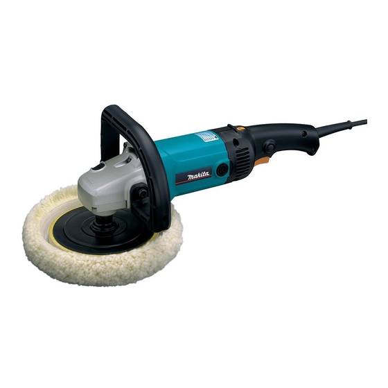
Sander Polisher
9227C
9227C
Advertisement

Related Manuals for Makita 9227C


Summary of Contents for Makita 9227C
- Page 1 Sander Polisher 9227C SPECIFICATIONS Model 9227C Max. capacities (dia.) Wool pad ............................. 180 mm Abrasive disc ............................180 mm –1 No load speed (min ) ......................... 0 – 3,000 Overall length ............................470 mm Net weight ..............................3.0 kg • Due to our continuing program of research and development, the specifications herein are subject to change without notice.
- Page 2 15° 15°...
- Page 3 Symbol The following show the symbol used for the tool. Be sure that you understand its meaning before use. [ Read instruction manual.
-
Page 4: Safety Instructions
ENGLISH Explanation of general view 1 Protrusion of loop handle 9 Backing pad 17 Tighten 2 Matching hole in gear housing 10 Spindle 18 Switch trigger 3 Shaft lock 11 Press 19 Lock button 4 Loop handle 12 Wool bonnet 20 Speed adjusting dial 5 Bolts 13 Lock nut... -
Page 5: Additional Safety Rules
18. Ensure that ventilation openings are kept clear 21. Warning when working in dusty conditions. If it should The use of any other accessory or attachment other than recommended in this operating instruc- become necessary to clear dust, first discon- tion or the catalog may present a risk of personal nect the tool from the main supply (use non injury. -
Page 6: Maintenance
• The speed adjusting dial can be turned only as far maintenance or adjustment should be carried out by a Makita Authorized Service Center. as 6 and back to 1. Do not force it past 6 or 1, or the speed adjusting function may no longer work. - Page 8 Made in Japan 884103D6...