YASKAWA SGMAH User Manual
Sigma ii series servo system
Hide thumbs
Also See for SGMAH:
- User manual (617 pages) ,
- User manual (408 pages) ,
- User manual (578 pages)
Table of Contents
Advertisement
Quick Links
Advertisement
Chapters
Table of Contents
Troubleshooting

Related Manuals for YASKAWA SGMAH


Summary of Contents for YASKAWA SGMAH
- Page 1 Sigma II Series Servo System User’s Manual...
- Page 3 Any warnings provided by YASKAWA must be promptly provided to the end user. YASKAWA offers an express warranty only as to the quality of its products in conforming to standards and specifications published in YASKAWA’s manual. NO OTHER WARRANTY, EXPRESS OR IMPLIED, IS OFFERED.
- Page 4 This page intentionally left blank.
- Page 5 Yaskawa. No patent liability is assumed with respect to the use of the information contained herein. Moreover, because Yaskawa is constantly striving to improve its high-quality products, the information contained in this manual is subject to change without notice.
- Page 6 This page intentionally left blank.
- Page 7 • Required for 200V, 11kW and 15kW amplifiers: Use of Yaskawa kit number JZSP-CKT75 for wiring the power input and output terminals of the SGDH- 1AAE, and JZSP-CKT1E for the SGDH-1EAE, or equivalent UL listed closed-loop ring terminal to accept 4 AWG and 2 AWG wires respectively.
- Page 8 Sigma II User’s Manual Table of Contents/Preface CAUTION • Do not connect a three-phase power supply to the U, V, or W output terminals. Doing so may result in injury or fire. • Securely fasten the power supply terminal screws and motor output terminal screws. Not doing so may result in fire.
- Page 9 The edition number appears on the front and back covers. • If the manual must be ordered due to loss or damage, inform your nearest Yaskawa representative or one of the offices listed on the back of this manual.
- Page 10 Sigma II User’s Manual Table of Contents/Preface Notes: viii...
-
Page 11: Table Of Contents
Sigma II User’s Manual Table of Contents/Preface Table of Contents 1. Checking Product and Part Names ......... 1 - 1 1.1 Checking the Sigma II Series Products on Delivery. - Page 12 Sigma II User’s Manual Table of Contents/Preface 3.3 Main Circuit Wiring ..........3 - 12 3.3.1 Names and Descriptions of Main Circuit Terminal.
- Page 13 Sigma II User’s Manual Table of Contents/Preface 5.2.6 Contact Input Speed Control ........5 - 32 5.2.7 Using Torque Control .
- Page 14 Sigma II User’s Manual Table of Contents/Preface 5.9 Reserved Parameters..........5 - 129 5.10 List of Upgraded Functions (Applicable only to SGDH amplifiers of version number or higher.) .
- Page 15 8.1.1 SGMAH Servomotors ........
- Page 16 Sigma II User’s Manual Table of Contents/Preface 9.2 Troubleshooting ........... 9 - 5 9.2.1 Troubleshooting Problems with Alarm Displays.
- Page 17 Sigma II User’s Manual Table of Contents/Preface Torque Control Mode ..........C - 9...
- Page 18 Sigma II User’s Manual Table of Contents/Preface...
-
Page 19: Checking Product And Part Names
Sigma II User’s Manual Chapter 1: Checking Product and Part Names 1 Checking Product and Part Names This chapter describes the procedure for checking products upon delivery as well as names for product parts. 1.1 Checking the Sigma II Series Products on Delivery..........1-2 1.1.1 Servomotors .................... -
Page 20: Checking The Sigma Ii Series Products On Delivery
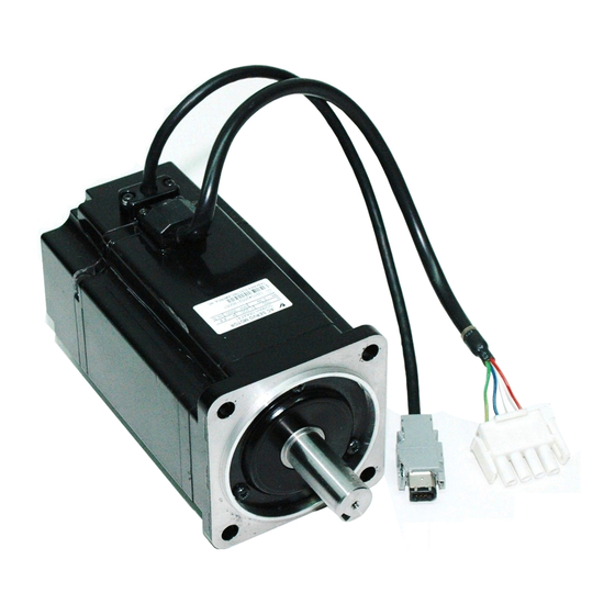
Are there any loose screws? Check screws for looseness using a screwdriver. If any of the above are faulty or incorrect, contact Yaskawa or an authorized distributor. 1.1.1 Servomotors External Appearance and Nameplate Example... - Page 21 SGMBH : A = 200% Peak Torque B = 250% Peak Torque Table 1.1: Servomotor Capacity (kW) SGMAH SGMPH SGMGH SGMSH SGMUH SGBMH SGMAH SGMPH SGMGH SGMSH SGMUH SGMBH Symbol Symbol 3000rpm 3000rpm 1500rpm 3000rpm 6000rpm 1500rpm 3000rpm 3000rpm 1500rpm 3000rpm 6000rpm 1500rpm 0.03...
-
Page 22: Direct-Drive Motor Supporting Function
Fn011-F. □□■■ "Voltage and Motor Model Display" □□: Voltage 00: 100 VAC or 140 VDC 01: 200 VAC or 280 VDC 02: Reserved ■■: Motor model 00: SGMAH 01: SGMPH 02: SGMSH 03: SGMGH-□A (1500 rpm) 04: SGMGH-□B (2000 rpm) 05: SGMDH 32: SGMCS-□□C... - Page 23 Sigma II User’s Manual Chapter 1: Checking Product and Part Names Model Designation SGMCS 02 B 3 A 1 1 Direct-drive motor Brake Specifications 1: Without brake Rated torque Flange Specifications 02: 2N-m 10: 10N-m 35: 35N-m 1: Back side only, base mount 04: 4N-m 14: 14N-m 45: 45N-m...
-
Page 24: Servo Amplifiers
Sigma II User’s Manual Chapter 1: Checking Product and Part Names 1.1.3 Servo Amplifiers External Appearance and Nameplate Examples Servo amplifier model YASKAWA 200V SERVOPACK SGDH- MODE/SET DATA/ POWER CHARGE Serial number Sigma II series SGDH Applicable capacity servo amplifier... - Page 25 A: 200V (Single-phase/3-phase) B: 100V* (Single-phase, 200W or less) D: 400V *The only 100V servomotors are the 0.2kW or less SGMAH and SGMPH Type D: For torque, speed, and position control (SGDM) E: For torque, speed, and position control (SGDH) Options/Design Sequence A: Design Sequence "A"...
-
Page 26: Product Part Names
Sigma II User’s Manual Chapter 1: Checking Product and Part Names 1.2 Product Part Names This section describes product part names. 1.2.1 Servomotors The figure below shows part names for servomotors with or without brakes. Encoder Frame Flange Output shaft 1 - 8... -
Page 27: Servo Amplifiers
Sigma II User’s Manual Chapter 1: Checking Product and Part Names 1.2.2 Servo Amplifiers The figure below shows the part names for servo amplifiers. Battery Holder Version Number Used to house the backup battery for an Indicates the Servo Amplifier hardware version and absolute encoder. - Page 28 Sigma II User’s Manual Chapter 1: Checking Product and Part Names Additional References Refer to the following manuals for information not included in this manual. Manual Name Manual Number Sigma-II Series Servo System Product Catalog G–MI#99001 Supplement Motion Products CD YEA–CD–MTN–1 Sigma-II Series SGDH User’s Manual YEA–SIA–S800–39.21...
-
Page 29: Installation
Sigma II User’s Manual Chapter 2: Installation 2 Installation This chapter describes precautions for Sigma II Series servomotor and servo amplifier installation. 2.1 Servomotors ......................2-2 2.1.1 Storage Temperature ................... 2-2 2.1.2 Installation Site ................... 2-2 2.1.3 Alignment ....................2-3 2.1.4 Orientation .................... -
Page 30: Servomotors
Sigma II User’s Manual Chapter 2: Installation 2.1 Servomotors SGM H servomotors can be installed either horizontally or vertically. The service life of the servomotor can be shortened or unexpected problems might occur if it is installed incorrectly or in an inappropriate location. Follow these installation instructions carefully. -
Page 31: Alignment
Sigma II User’s Manual Chapter 2: Installation • Relative humidity (r.h.) of 20 to 80% with no condensation. • Accessible for inspection and cleaning. 2.1.3 Alignment Align the shaft of the servomotor with the shaft of the equipment, and then couple the shafts. -
Page 32: Allowable Shaft Loads
Allowable Radial Load Thrust Load Servomotor MODEL Reference Diagram in (mm) 15.29 (68) 12.14 (54) 0.79 (20) 17.54 (78) SGMAH 55.1 (245) 16.63 (74) 0.98 (25) 88.1 (392) 33.0 (147) 1.39 (35) 17.54 (78) 11.02 (49) 0.79 (20) 55.1 (245) 15.29 (68) -
Page 33: Vibration Resistance
Mount the servomotor with the shaft positioned horizontally. The servomotor will withstand the following levels of vibration on all three axes: front-to-back (X), vertical (Y), and side-to-side (Z). • SGMAH, SGMPH: 49m/s (5G) • SGMSH, SGMGH, SGMDH, SGMUH, and SGMBH: 24.5m/s (2.5G) -
Page 34: Vibration Class
Sigma II User’s Manual Chapter 2: Installation 2.1.7 Vibration Class The vibration class for SGM H servomotors operating at rated speed is 15μm (maximum). Position for measuring vibration 2.1.8 Handling Oil and Water Install a protective cover over the servomotor if it is used in a location that is subject to water or oil mist. -
Page 35: Servo Amplifiers
Follow the installation instructions below. 2.2.1 Storage Conditions Store the servo amplifier within the following temperature range, as long as it is stored with the power cable disconnected. -20 to 85°C YASKAWA 200V SERVOPACK SGDH- MODE/SET DATA/ POWER... -
Page 36: Orientation
Sigma II User’s Manual Chapter 2: Installation 2.2.3 Orientation Install the servo amplifier perpendicular to the wall as shown in the figure. The servo amplifier must be oriented this way because it is designed to be cooled by natural convection or by a cooling fan. Secure the servo amplifier using the mounting holes. -
Page 37: Installation
Sigma II User’s Manual Chapter 2: Installation 2.2.4 Installation Follow the procedure below to install multiple servo amplifiers side by side in a control panel. 1.97in (50mm) minimum 1.97in (50mm) minimum 1.18in (30mm) 0.39in (10mm) minimum Servo Amplifier Orientation Install the servo amplifier perpendicular to the wall so the front panel containing connectors faces outward. - Page 38 Sigma II User’s Manual Chapter 2: Installation NOTES: 2 - 10...
-
Page 39: Wiring
Sigma II User’s Manual Chapter 3: Wiring 3 Wiring This chapter describes the procedure used to connect Sigma II Series products to peripheral devices and gives typical exam- ples of main circuit wiring as well as I/O signal connections. 3.1 Connecting to Peripheral Devices................ 3-3 3.1.1 Single-Phase (100V or 200V) Main Circuit Specifications...... - Page 40 Sigma II User’s Manual Chapter 3: Wiring 3.5.2 CN2 Encoder Connector Terminal Layout and Types ......3-26 3.6 Examples of Standard Connections ..............3-27 3.6.1 Single-Phase Power Supply Specifications ..........3-27 3.6.2 Three-Phase Power Supply Specifications (200V)........3-28 3.6.3 Three-Phase Power Supply Specifications (400V)........3-29 Large Capacity, 400V ................
-
Page 41: Connecting To Peripheral Devices
Sigma II User’s Manual Chapter 3: Wiring 3.1 Connecting to Peripheral Devices This section provides examples of standard Sigma II Series product connections to peripheral devices. It also briefly explains how to connect each peripheral device. 3 - 3... -
Page 42: Single-Phase (100V Or 200V) Main Circuit Specifications
Sigma II User’s Manual Chapter 3: Wiring 3.1.1 Single-Phase (100V or 200V) Main Circuit Specifications Connect the SGDH servo amplifier Host to a Yaskawa host controller or to Controller one made by another company. MEMOCON GL120, GL130 with a motion module. Power supply... -
Page 43: Three-Phase (200V) Main Circuit Specifications
Sigma II User’s Manual Chapter 3: Wiring 3.1.2 Three-Phase (200V) Main Circuit Specifications Connect the SGDH servo amplifier Host to a Yaskawa host controller or to Controller one made by another company. MEMOCON GL120, GL130 with a motion module. Power supply... -
Page 44: Three-Phase (400V) Main Circuit Specifications
Sigma II User’s Manual Chapter 3: Wiring 3.1.3 Three-Phase (400V) Main Circuit Specifications Connect the SGDH servo amplifier Host to a Yaskawa host controller or to Power supply for Brake Controller one made by another company. Supplied by 100V or 200V... -
Page 45: Servo Amplifier Internal Block Diagrams
Sigma II User’s Manual Chapter 3: Wiring 3.2 Servo Amplifier Internal Block Diagrams The following sections show internal block diagrams of the servo amplifiers. 3.2.1 30W to 400W (200V) and 30W to 200W (100V) Models Single-phase +10% 200 to 230 V -15% (50/60Hz) THS1... -
Page 46: Kw To 1.5Kw (200V) Models
Sigma II User’s Manual Chapter 3: Wiring 3.2.2 0.5kW to 1.5kW (200V) Models Three-phase +10% 200 to 250V -15% FAN1 (50\60Hz) ±12V D2 D3 D4 AC servomotor Noise filter CHARGE THS1 Gate drive over- Voltage current protection Relay drive Gate drive sensor Voltage sensor... -
Page 47: Kw To 15.0Kw (200V) Models
Sigma II User’s Manual Chapter 3: Wiring 3.2.4 6.0kW to 15.0kW (200V) Models Regenerative Resistor (optional) Three-phase +10% 200 to 250V -15% THS1 (50\60Hz) FAN1 PM1/PM2/PM3 ±12V AC servomotor Line filter CHARGE SCR1 Base drive over-current protection isolator Voltage sensor Voltage Relay drive isolator... -
Page 48: Kw (400V) Models
Sigma II User’s Manual Chapter 3: Wiring 3.2.6 5.0kW (400V) Models Three-phase +10% 200 to 250V -15% (50\60Hz) FAN1 ±12V AC servomotor Line filter CHARGE L1 BA1 BA3 — — SCR1 — Gate drive over- Relay Voltage Gate current protector drive sensor drive... -
Page 49: Kw To 15.0Kw (400V) Models
Sigma II User’s Manual Chapter 3: Wiring 3.2.8 11.0kW to 15.0kW (400V) Models Regenerative resistor (optional) Three-phase +10% 200 to 250V -15% (50\60Hz) FAN1 AC servomotor Noise filter ±12V CHARGE Gate drive over- current protection RLY1 Control power +24V Voltage (not provided) Relay drive Gate drive... -
Page 50: Main Circuit Wiring
Must be used with UL listed fuses or circuit breakers, in accordance with the National Electrical Code. • Required for 7.5kW -15kW (200V) or 6kW-15kW (400V) amplifiers: Must use ring terminals specified in Yaskawa Kits JZSP-CKT75, JZSP-CKT1E, JZSP-CKT75DE, JZSP- CKT1ADE, and JZSP-CKT1EDE for wiring of input and output power. Contact Yaskawa for details. 3 - 12... -
Page 51: Names And Descriptions Of Main Circuit Terminal
Sigma II User’s Manual Chapter 3: Wiring 3.3.1 Names and Descriptions of Main Circuit Terminal The following table gives the names and a description of main circuit terminals. Main Circuit Names and Description Terminal Name Description Symbol 30W to 200W Single-phase 100 to 115V (+10%, -15%), 50/60Hz 30W to 400W Single-phase 200 to 230V (+10%, -15%), 50/60Hz... -
Page 52: Typical Main Circuit Wiring Example
Sigma II User’s Manual Chapter 3: Wiring 3.3.2 Typical Main Circuit Wiring Example The following figure shows a typical example of main circuit wiring. Servo Amplifier 1MCCB SGDH- +24V (For servo alarm display) Main Main power supply power supply ALM-SG 1SUP 1Ry: Relay 1MCCB: Molded-case circuit breaker (for the inverter) -
Page 53: Servo Amplifier Power Losses
Sigma II User’s Manual Chapter 3: Wiring 3.3.4 Servo Amplifier Power Losses The following table shows servo amplifier power losses at the rated output. Servo Amplifier Power Losses at Rated Output Maximum Main Control Output Regenerative Total Applicable Circuit Circuit Current Resistor Power Power... -
Page 54: Wiring Main Circuit Terminal Blocks
Sigma II User’s Manual Chapter 3: Wiring 3.3.5 Wiring Main Circuit Terminal Blocks Observe the following precautions when wiring main circuit terminal blocks. CAUTION • Remove the terminal block from the servo amplifier prior to wiring. • Insert only one wire per terminal on the terminal block. •... -
Page 55: I/O Signals
Sigma II User’s Manual Chapter 3: Wiring 3.4 I/O Signals This section describes I/O signals for the SGDH servo amplifier 3.4.1 Example of Typical I/O Signal Connections SGDH Servo Amplifier V-REF LPF* ALO1 Alarm code maximum output: ALO2 Operating voltage: 30V Operating current: 20mA T-REF LPF*... -
Page 56: List Of Cn1 Terminals
Sigma II User’s Manual Chapter 3: Wiring 3.4.2 List of CN1 Terminals The following diagram shows the layout and specifications of CN1 terminals. CN1 Terminal Layout Speed coin- /V-CMP- cidence (/COIN-) detection TGON sig- output /TGON+ nal output Open-collec- TGON sig- tor reference /TGON nal output... -
Page 57: I/O Signal Names And Functions
Sigma II User’s Manual Chapter 3: Wiring 3.4.3 I/O Signal Names and Functions The following section describes servo amplifier I/O signal names and functions. Input Signals Signal Name Function Reference Servo ON: Turns ON the servomotor when the gate block in the inverter is /S-ON 5.5.2 released. - Page 58 Sigma II User’s Manual Chapter 3: Wiring Output Signals Signal Name Function Reference Number ALM+ Servo alarm: Turns OFF when an error is detected. 5.5.1 ALM- Detection during servomotor rotation: detects whether the servomotor is /TGON+ rotating at a speed higher than the motor speed setting. Motor speed 5.5.5 /TGON- detection can be set via parameter.
-
Page 59: Interface Circuits
Sigma II User’s Manual Chapter 3: Wiring 3.4.4 Interface Circuits This section shows examples of servo amplifier I/O signal connection to the host controller. Interface for Reference Input Circuits Analog Input Circuit Analog signals are either speed or torque reference signals at the impedance below. •... - Page 60 Sigma II User’s Manual Chapter 3: Wiring The following examples show how to select the pull-up resistor R1 so the input current (I) falls between 7 and 15mA. Application Examples R1 = 2.2kΩ with R1 = 1kΩ with R1 = 180Ω with = 24V ±5% = 12V ±5% = 5V ±5%...
- Page 61 Sigma II User’s Manual Chapter 3: Wiring See 3.5 Wiring Encoders (for SGMGH and SGMSH Motors Only) for con- nection circuit examples. • Connecting to an Open-collector Output Circuit Alarm code signals are output from open-collector transistor output circuits. Connect an open-collector output circuit through a photocoupler, relay, or line receiver circuit.
-
Page 62: Wiring Encoders (For Sgmgh And Sgmsh Motors Only)
CN2 of the servo amplifier, and PG output signals from CN1 to the controller. This applies to both incremental and absolute encoders of SGMGH and SGMSH motors only. The numbers in parentheses ( ) are applicable to SGMAH motors. For SGMPH motors, refer to the Sigma II Servo System Product Catalog Supplement. - Page 63 Sigma II User’s Manual Chapter 3: Wiring Absolute Encoders Absolute encoder Servo amplifier 1-33 A phase 1-34 /PAO C (5) 1-35 B phase 1-36 /PBO D (6) 1-19 C phase 1-20 /PCO 1-48 S phase 1-49 /PSO H (1) PG5V G (2) Applicable line PG0V...
-
Page 64: Cn2 Encoder Connector Terminal Layout And Types
The following encoder connectors are for the SGMGH and SGMSH servomotor: L-shaped plug: MS3108B20-29S Straight: MS3106B20-29S Cable clamp: MS3057-12A Note: Encoder cables are available from Yaskawa. For more details on the cables, see Sigma II Series Servo System Catalog Supplement (G-MI#99001). 3 - 26... -
Page 65: Examples Of Standard Connections
Sigma II User’s Manual Chapter 3: Wiring 3.6 Examples of Standard Connections The following diagrams show examples of standard servo amplifier connections by specifications and type of control. 3.6.1 Single-Phase Power Supply Specifications Single-phase 200 to 230V Single-phase 100 to 115V (50/60Hz) (50/60Hz) 1MCCB... -
Page 66: Three-Phase Power Supply Specifications (200V)
Sigma II User’s Manual Chapter 3: Wiring 3.6.2 Three-Phase Power Supply Specifications (200V) Three-phase 200 to 230V (50/60Hz) 1MCCB Power Power Alarm Noise filter processing Be sure to attach a surge suppressor to the excitation coil of the magnetic contactor and relay. Servomotor A (1) B (2) -
Page 67: Three-Phase Power Supply Specifications (400V)
Sigma II User’s Manual Chapter 3: Wiring 3.6.3 Three-Phase Power Supply Specifications (400V) Three-phase 380 to 480V (50/60Hz) 1MCCB Power Power Alarm Noise filter processing Be sure to attach a surge suppressor to the excitation coil of the magnetic contactor and relay. Servomotor A (1) B (2) - Page 68 Sigma II User’s Manual Chapter 3: Wiring 400V (22kW, 30kW) Three-phase 380 to 480V -15 % (50/60Hz) 1MCCB Noise filter Power Power Be sure to attach a surge suppressor to the excitation coil of U(A) V(B) W(C) the magnetic contactor and relay.
- Page 69 Sigma II User’s Manual Chapter 3: Wiring 400V (37kW to 55kW) Three-phase 380 to 480V -15 % (50/60Hz) 1MCCB Noise filter Power Power Be sure to attach a surge suppressor to the excitation coil of U(A) V(B) W(C) the magnetic contactor and relay.
-
Page 70: Position Control Mode
Sigma II User’s Manual Chapter 3: Wiring 3.6.4 Position Control Mode Three-phase 200 to 230V (50/60Hz) 1MCCB Power Power Alarm Noise filter processing Be sure to attach a surge suppressor to the excitation coil of the magnetic contactor and relay. Servomotor A (1) B (2) -
Page 71: Speed Control Mode
Sigma II User’s Manual Chapter 3: Wiring 3.6.5 Speed Control Mode Three-phase 200 to 230V (50/60Hz) 1MCCB Power Power Alarm Noise filter processing Be sure to attach a surge suppressor to the excitation coil of the magnetic contactor and relay. Servomotor A (1) B (2) -
Page 72: Torque Control Mode
Sigma II User’s Manual Chapter 3: Wiring 3.6.6 Torque Control Mode Three-phase 200 to 230V (50/60Hz) 1MCCB Power Power Alarm Noise filter processing Be sure to attach a surge suppressor to the excitation coil of the magnetic contactor and relay. Servomotor A (1) B (2) -
Page 73: Trial Operation
Sigma II User’s Manual Chapter 4: Trial Operation 4 Trial Operation This chapter describes a two-step trial operation. Be sure to complete step 1 before proceeding to step 2. 4.1 Two-Step Trial Operation ..................4-2 4.1.1 Step 1: Trial Operation for Servomotor without Load........ 4-3 4.1.2 Step 2: Trial Operation with the Servomotor Connected to a Load.... -
Page 74: Two-Step Trial Operation
Operation with the Servomotor Connected to a Load for more details on the trial opera- tion. Step 1: Trial Operation for Servomotor without Load Make sure the servomotor is wired properly and then turn the shaft prior to connecting the servomotor to the equipment. YASKAWA 200V SERVOPACK SGDM- MODE/SET... -
Page 75: Step 1: Trial Operation For Servomotor Without Load
• Check servomotor wiring. • Check CN1 I/O signal wiring. Make sure the host controller and other adjustments are completed as much as possible in step 1 (prior to connecting the servomotor to equipment). YASKAWA 200V SERVOPACK SGDH- MODE/SET DATA/... - Page 76 Do not connect anything to the sha (no-load conditions). Secure the servomotor mounting plate to the equipment in order to prevent the servomotor from moving during operation. 2. Check the wiring. YASKAWA 200V SERVOPACK SGDH MODE/SET DATA/...
- Page 77 Sigma II User’s Manual Chapter 4: Trial Operation 4. Operate with the panel operator. YASKAWA 200V SERVOPACK SGDH- Panel operator MODE/SET DATA/ CHARGE POWER Operate the servomotor using the panel operator. Check to see if the servomotor runs normally. See 7.2.2 JOG Operation Using the Digital Operator for more details on the procedure.
- Page 78 Sigma II User’s Manual Chapter 4: Trial Operation Input Signal Status LED Display OFF (high level) Top LED indicators light. ON (low level) Bottom LED indicators light. Note: The servomotor will not operate properly if the following signal lines are not wired correctly. Always wire them correctly.
- Page 79 Sigma II User’s Manual Chapter 4: Trial Operation b. Turn ON the servo ON signal. Display with the servo ON. Set /S-ON (CN1-40) to 0V. If normal, the servomotor will turn ON and the LED indicator on the front panel will display as shown above. If an alarm display appears, take appropriate action as described in 9.2 Troubleshooting.
- Page 80 Sigma II User’s Manual Chapter 4: Trial Operation 4. Reset the following parameters to change the motor speed or direction of rotation. Sets the reference speed input gain Pn300 See 5.2.1 Speed Reference. Selects the rotation direction. Pn000.0 See 5.1.1 Switching Servomotor Rotation Direction. Operating Procedure In Position Control Mode: Set Pn000.1 to 1 1.
-
Page 81: Step 2: Trial Operation With The Servomotor Connected To A Load
Sigma II User’s Manual Chapter 4: Trial Operation 4.1.2 Step 2: Trial Operation with the Servomotor Connected to a Load WARNING Follow the procedure below for step 2 operation precisely as given. Malfunctions that occur after the servomotor is connected to the equipment not only damage the equipment, but may also cause an accident resulting in death or injury. -
Page 82: Additional Setup Procedures In Trial Operation
Sigma II User’s Manual Chapter 4: Trial Operation 4.2 Additional Setup Procedures in Trial Operation Before starting trial operation, precautionary setup procedures must be followed when either of two equipment configurations are used. These are delineated in the two subsequent sections. 4.2.1 Servomotors with Brakes Use a servomotor with a brake for vertical shaft applications or when external force... -
Page 83: Position Control By Host Controller
Sigma II User’s Manual Chapter 4: Trial Operation 4.2.2 Position Control by Host Controller If the position control algorithm of the host controller has not been established or finalized, disconnect the servomotor from the equipment before performing a trial operation. This will prevent the servomotor from running out of control and damaging the equipment. -
Page 84: Minimum Parameters And Input Signals
Sigma II User’s Manual Chapter 4: Trial Operation 4.3 Minimum Parameters and Input Signals This section of this manual describes the minimum parameters and input signals required for trial operation. 4.3.1 Parameters See 7.1.6 Operation in Parameter Setting Mode for more details on setting parameters. -
Page 85: Parameter Settings And Functions
Sigma II User’s Manual Chapter 5: Parameter Settings and Functions 5 Parameter Settings and Functions This chapter describes the procedure for setting and applying parameters. 5.1 Settings According to Device Characteristics ............. 5-5 5.1.1 Switching Servomotor Rotation Direction ..........5-5 5.1.2 Setting the Overtravel Limit Function ............ - Page 86 Sigma II User’s Manual Chapter 5: Parameter Settings and Functions 5.5.2 Using the Servo ON Input Signal (/S-ON) ..........5-72 5.5.3 Using the Positioning Completed Output Signal (/COIN) ....... 5-73 5.5.4 Speed Coincidence Output (/V-CMP)............5-75 5.5.5 Using the Running Output Signal (/TGON) ..........5-76 5.5.6 Using the Servo Ready Output Signal (/S-RDY) ........
- Page 87 Sigma II User’s Manual Chapter 5: Parameter Settings and Functions 5.11 Improved Functions (Applicable only to SGDH amplifiers of version #33ooo or higher.) ......................5-139 5.11.1 Moment of Inertia Ratio Setting Range ..........5-139 5.11.2 Adaptation to Single-turn Data Absolute Encoder ......... 5-139 5.11.3 Improvement of Linear Motor Related Specifications ......
-
Page 88: Parameters
Sigma II User’s Manual Chapter 5: Parameter Settings and Functions Before Reading this Chapter This chapter describes the use of each CN1 connector I/O signals in the SGDH servo amplifier as well as the procedure for setting the related parameters for the intended purposes. -
Page 89: Settings According To Device Characteristics
Sigma II User’s Manual Chapter 5: Parameter Settings and Functions 5.1 Settings According to Device Characteristics This section describes the procedure for setting parameters according to the dimensions and performance characteristics of the equipment used. 5.1.1 Switching Servomotor Rotation Direction The servo amplifier has a Reverse Rotation Mode that reverses the direction of servomotor rotation without rewiring. -
Page 90: Setting The Overtravel Limit Function
Sigma II User’s Manual Chapter 5: Parameter Settings and Functions 5.1.2 Setting the Overtravel Limit Function The overtravel limit function forces movable equipment parts to stop if they exceed the allowable range of motion. Using the Overtravel Function To use the overtravel function, connect the overtravel limit switch input signal terminals shown below to the correct pins of the servo amplifier CN1 connector. - Page 91 Sigma II User’s Manual Chapter 5: Parameter Settings and Functions Enabling/Disabling Input Signals Set the following parameters to specify whether input signals are used for overtravel or not. The default setting is “used.” Parameter Signal Setting Control Mode P-OT Signal Mapping Speed/Torque Control, Pn50A.3 Default Setting: 2...
- Page 92 Sigma II User’s Manual Chapter 5: Parameter Settings and Functions Parameter Signal Setting Control Mode Speed/Torque Control, Pn001.1 Overtravel Stop Mode Default Setting: 0 Position Control After stopping Stop Mode Pn001.1 Overtravel setting Pn001.0 = 0, 1 Stop by dynamic brake Pn001.1 = 0 Coast status Coast to a stop...
-
Page 93: Limiting Torque
Sigma II User’s Manual Chapter 5: Parameter Settings and Functions 5.1.3 Limiting Torque The SGDH servo amplifier limits torque as follows: • Level 1: Limits maximum output torque to protect the equipment or workpiece. • Level 2: Limits torque after the servomotor moves the equipment to a specified position (internal torque limit). - Page 94 Sigma II User’s Manual Chapter 5: Parameter Settings and Functions Application Example: Equipment Protection Torque limit Too small a torque limit will result in a insufficient torque during acceleration and Motor deceleration. speed Torque Using the /CLT Signal The following section describes the use of the contact output signal /CLT as a torque limit output signal.
- Page 95 Sigma II User’s Manual Chapter 5: Parameter Settings and Functions Pn50F.0 Output terminal CN1-25, 26 (SO1) Torque limit CN1-27, 28 (SO2) detection CN1-29, 30 (SO3) Use the following table to select which terminal will output the /CLT signal. Output Terminal (CN1-) Parameter Setting —...
- Page 96 Sigma II User’s Manual Chapter 5: Parameter Settings and Functions This is the external torque (current) limit input for forward and reverse rotation. Check input signal allocation status when using this function. (See 5.3.3 Input Circuit Signal Allocation). Default settings are given in the table on the following page.
- Page 97 Sigma II User’s Manual Chapter 5: Parameter Settings and Functions Set the torque limits when the torque is limited by an external contact input. Setting Description /P-CL (CN1-45) Input Pn404 torque limit applied. /N-CL (CN1-46) Input Pn405 torque limit applied. See 5.2.10 Torque Limiting by Analog Voltage Reference.
-
Page 98: Settings According To Host Controller
Input voltage (V) Rated motor speed The slope is set in Pn300. Setting Examples Pn300 = 600: This setting means that 6V is equivalent to the rated motor speed. Speed Reference SGMAH Rotation Direction Motor Speed Input Servomotor Forward rotation... - Page 99 Sigma II User’s Manual Chapter 5: Parameter Settings and Functions Input Circuit Example Servo Amplifier 470Ω, ½W minimum 2kΩ + 12V CN1-5 CN1-6 • Always use twisted pair cable for noise control. Recommended variable resistor: Model 25HP-10B manufactured by Sakae Tsushin Kogyo Co., Ltd.
-
Page 100: Position Reference
Sigma II User’s Manual Chapter 5: Parameter Settings and Functions Using the /P-CON Signal Speed Control, Proportional Control Reference Input P-CON CN1-41 Position Control The /P-CON input signal switches the Speed Control Mode from PI (proportional-integral) to P (proportional) control. Proportional control can be used in the following two ways: •... - Page 101 Sigma II User’s Manual Chapter 5: Parameter Settings and Functions Connection Example 1: Line-driver Output Applicable line driver: SN75174 manufactured by Texas Instruments Inc., MC3487 or equivalent Host controller Servo amplifier Photocoupler PULS CN1-7 Line-driver 150Ω /PULS CN1-8 SIGN CN1-11 /SIGN CN1-12 CN1-15...
- Page 102 Sigma II User’s Manual Chapter 5: Parameter Settings and Functions Servo Amplifier Host controller CN1-3 1kΩ +12V CN1-7 Photocoupler Approx. PULS 150Ω /PULS CN1-8 CN1-13 CN1-11 SIGN CN1-12 ON: 1.5V maximum /SIGN CN1-18 CN1-15 CN1-14 /CLR CN1-1 P represents twisted pair wires Note: The noise margin of the input signal will decrease if the reference pulse is provided by an open-collector output.
- Page 103 Sigma II User’s Manual Chapter 5: Parameter Settings and Functions Since the reference pulse form can be selected from among those listed below, set one according to host controller specifications. Input Parameter Reference Forward Rotation Reverse Rotation Pulse Logic Pn200.0 Pulse Form Reference Reference...
- Page 104 Sigma II User’s Manual Chapter 5: Parameter Settings and Functions Example of I/O Signal Generation Timing Servo ON Release t1 ≤ 30ms t2 ≤ 6ms Baseblock (when parameter CN1-11 Pn506 is set to 0) CN1-1 t3 ≥ 40ms Sign+pulse train CN1-7 CN1- t4, t5, t6 ≤...
- Page 105 Sigma II User’s Manual Chapter 5: Parameter Settings and Functions Error Counter Clear Input The procedure for clearing the error counter is described below. Clear Input Position Control Input CLR CN1-15 Clear Input Position Control Input /CLR CN1-14 The following occur when the CLR signal is set to high level. Servo Amplifier Clear Position loop...
-
Page 106: Using The Encoder Signal Output
Sigma II User’s Manual Chapter 5: Parameter Settings and Functions 5.2.3 Using the Encoder Signal Output Encoder output signals divided inside the servo amplifier can be output externally. These signals can be used to form a position control loop in the host controller. Servo amplifier Host controller (Servomotor) - Page 107 Sigma II User’s Manual Chapter 5: Parameter Settings and Functions I/O Signals I/O signals are described below. Speed/Torque Control, Output PAO CN1-33 Encoder Output Phase A Position Control Speed/Torque Control, Output /PAO CN1-34 Encoder Output Phase /A Position Control Speed/Torque Control, Output PBO CN1-35 Encoder Output Phase B...
- Page 108 Sigma II User’s Manual Chapter 5: Parameter Settings and Functions Input SEN CN1-4 SEN Signal Input Speed/Torque Control Input /SEN CN1-2 Signal Ground Speed/Torque Control Speed/Torque Control, Output PSO CN1-48 Encoder Output Phase S Position Control Speed/Torque Control, Output /PSO CN1-49 Encoder Output Phase /S Position Control Speed/Torque Control,...
- Page 109 Sigma II User’s Manual Chapter 5: Parameter Settings and Functions Pulses from the servomotor encoder (PG) are divided by the preset number before being output. The number of output pulses per revolution is set at this parameter. Set the value using the reference units of the equipment or the controller used.
-
Page 110: Sequence I/O Signals
External power supply specifications: 24V ±1 V , 50mA minimum. Yaskawa recommends using the same type of external power supply as that used for output circuits. The function allocation for sequence input signal circuits can be changed. See 5.3.3 Input Circuit Signal Allocation for more details. - Page 111 Host controller Note: Provide a separate external I/O power supply; the servo amplifier does not have an internal 24V power supply. Yaskawa recommends using the same type of external power supply as that used for input circuits. Function allocation for some sequence output signal circuits can be changed.
-
Page 112: Using The Electronic Gear Function
Sigma II User’s Manual Chapter 5: Parameter Settings and Functions 5.2.5 Using the Electronic Gear Function The electronic gear function enables the servomotor travel distance per input reference pulse to be set to any value. It allows the pulses generated by the host controller to be used for control without having to consider the equipment gear ratio or the number of encoder pulses. - Page 113 Sigma II User’s Manual Chapter 5: Parameter Settings and Functions number of encoder signal pulses (A and B phase) output from the servo amplifier. 3. Determine the reference unit used. A reference unit is the minimum position data unit used to move a load. (Minimum unit of reference from the host controller).
- Page 114 Sigma II User’s Manual Chapter 5: Parameter Settings and Functions ⎛ ⎞ -- - 5. Electronic gear ratio is given as: ⎝ ⎠ -- - If the gear ratio of the motor and the load shaft is given as: where m is the rotation of the motor and n is the rotation of the load shaft, ×...
- Page 115 Sigma II User’s Manual Chapter 5: Parameter Settings and Functions Electronic Gear Setting Examples The following examples show electronic gear settings for different load mechanisms. Ball Screws Reference unit 0.00004in (0.0001mm) 0.24in Travel distance per load shaft revolution = = 6000 Load shaft Load shaft 0.00004in...
-
Page 116: Contact Input Speed Control
Sigma II User’s Manual Chapter 5: Parameter Settings and Functions Control Block Diagram The following diagram illustrates a control block for position control. Servo Amplifier (position control) Pn109 Pn202 Pn10A Pn107 Feed- Differentiation Primary forward gain Bias lag filter Pn108 Pn203 Bias addition Pn200.0... - Page 117 Sigma II User’s Manual Chapter 5: Parameter Settings and Functions Using Contact Input Speed Control Follow steps 1 to 3 below to use the contact input speed control function. 1. Set contact input speed control as shown below. Parameter Signal Setting Control Mode Speed/Torque Control,...
- Page 118 Sigma II User’s Manual Chapter 5: Parameter Settings and Functions 2. Set the motor speeds with the following parameters. Setting Parameter Signal Control Mode (rpm) Speed 1 (SPEED 1) Range: 0 to 10000 Pn301 Speed Control (Contact Input Speed Control) Default Setting: 100 Speed 2 (SPEED 2) Range: 0 to 10000...
- Page 119 Sigma II User’s Manual Chapter 5: Parameter Settings and Functions Smooth speed control can be performed by entering a progressive speed reference or using contact input speed control. Set each constant to 0 for normal speed control. Set each parameter to the following time intervals. •...
- Page 120 Sigma II User’s Manual Chapter 5: Parameter Settings and Functions Direction of Rotation Selection The input signal /P-CON(/SPD-D) is used to specify the direction of servomotor rotation. Speed/Torque Control, Input /P-CON CN1-41 Proportional Control Reference, etc. Position Control • When contact input speed control is used, the input signal /P-CON (/SPD-D) specifies the direction of servomotor rotation.
-
Page 121: Using Torque Control
Sigma II User’s Manual Chapter 5: Parameter Settings and Functions pulse reference output from the host controller after a positioning completed signal is output from the servo amplifier. Signal Generation Timing for Position Control Motor Speed 0rpm /COIN Pulse Reference /P-CL (/SPD-A) /N-CL (/SPD-B) Selected Speed... - Page 122 Sigma II User’s Manual Chapter 5: Parameter Settings and Functions Application Examples • Tension control • Pressure control Control Mode Pn000.1 Torque Control Servo amplifier This is a dedicated Torque Control Mode. •A torque reference is input from T-REF (CN1-9). Torque T-REF •Speed reference input V-REF (CN1-5) cannot be...
- Page 123 Sigma II User’s Manual Chapter 5: Parameter Settings and Functions Pn000.1 Control Method Speed Control: When /P-CON (/C-SEL) is ON Set the parameter Pn002.0 as shown below. Speed Reference Torque Reference Parameter Input Input Pn002.0 Comments (V-REF) (T-REF) State (CN1-5,6) (CN1-9,10) Speed Control Speed Reference...
- Page 124 Sigma II User’s Manual Chapter 5: Parameter Settings and Functions Input Signals Torque Reference Inputs The following input signals are used for torque control. Servo Amplifier T-REF CN1-9 Torque Torque reference input CN1-10 reference (Analog voltage input) V-REF CN1-5 Speed Speed reference input CN1-6 reference...
- Page 125 Sigma II User’s Manual Chapter 5: Parameter Settings and Functions Example of an Input Circuit Servo Amplifier 470Ω 1/2W minimum +12V 2kΩ T-REF CN1-9 CN1-10 Note: • Always use twisted pair cables for noise control. • Recommended variable resistor: Model 25HP-10B manufactured by Sakae Tsushin Kogyo Co., Ltd.
- Page 126 Sigma II User’s Manual Chapter 5: Parameter Settings and Functions Torque Control Parameter The following parameter is used for torque control. Set the parameter according to requirements of the servo system that is used. Setting Parameter Signal Control Mode (0.1V x rated torque) Setting Range: 10 to 100 Pn400 Torque Reference Input Gain...
- Page 127 Sigma II User’s Manual Chapter 5: Parameter Settings and Functions The maximum speed of the servomotor will be used if Pn407 is set to a value higher than the maximum speed of the servomotor. External Speed Limit function: This function sets the voltage range for speed reference input V-REF (CN1-5) according to the output range of the host controller or external circuit.
-
Page 128: Torque Feed-Forward Function
Sigma II User’s Manual Chapter 5: Parameter Settings and Functions 5.2.8 Torque Feed-Forward Function The torque feed-forward function is used only in speed control (analog reference). This function is used to: • Shorten positioning time. • Differentiate a speed reference at the host controller to generate a torque feed-forward reference. -
Page 129: Speed Feed-Forward Function
Sigma II User’s Manual Chapter 5: Parameter Settings and Functions Setting Torque feed-forward is set using parameter Pn400. The default setting at Pn400 is 30. If, for example, the torque feed-forward value is ±3V, then torque is limited to ±100% of the rated torque. Setting Parameter Signal... - Page 130 Sigma II User’s Manual Chapter 5: Parameter Settings and Functions Using the Speed Feed-Forward Function To use the speed feed-forward function, set the following parameter to 1. Parameter Signal Setting Control Mode Pn207.1 Speed Control Option Default Setting: 0 Position Control This setting enables the speed feed-forward function.
-
Page 131: Torque Limiting By Analog Voltage Reference
Sigma II User’s Manual Chapter 5: Parameter Settings and Functions 5.2.10 Torque Limiting by Analog Voltage Reference Torque limiting by analog voltage reference limits torque by assigning a torque analog voltage to the T-REF terminal (CN1-9 and 10). It cannot be used for torque control because the torque reference input terminal T-REF is used as an input terminal. - Page 132 Sigma II User’s Manual Chapter 5: Parameter Settings and Functions settings. Input Signal Level Description Comments Signal Limit value: either Pn404 or CN1-45 is at “L” level when Torque is limited at the T-REF input, whichever is forward run side. smaller.
-
Page 133: Reference Pulse Inhibit Function (/Inhibit)
Sigma II User’s Manual Chapter 5: Parameter Settings and Functions 5.2.11 Reference Pulse Inhibit Function (/INHIBIT) This function inhibits the servo amplifier from counting input reference pulses during position control. The servomotor remains locked (clamped) while the function is in use. The /P-CON(/INHIBIT) signal is used to enable or disable the function. - Page 134 Sigma II User’s Manual Chapter 5: Parameter Settings and Functions Relationship between Inhibit Signal and Reference Pulses /INHIBIT signal (/P-CON) Reference pulse t1, t2 ≥ 0.5ms Input reference pulses are not counted during this period. 5 - 50...
-
Page 135: Setting Up The Servo Amplifier
Sigma II User’s Manual Chapter 5: Parameter Settings and Functions 5.3 Setting Up the Servo Amplifier This section describes the procedure for setting parameters to operate the SGDH servo amplifier. 5.3.1 Parameters The Sigma IΙ Series servo amplifier provides many functions and has parameters that allow the user to specify functions and perform fine adjustments. -
Page 136: Jog Speed
Use this parameter to set the motor speed when operating the servomotor from a panel or digital operator. If the setting is higher than the maximum motor speed of the servomotor, then the servomotor will rotate at its maximum speed. SERVOPACK 200V SGDH- YASKAWA MODE/SET DATA/ CHARGE POWER Digital Operator... -
Page 137: Input Circuit Signal Allocation
Pn50A.0 Setting Description Default setting for sequence input signal allocation. This setting is the same as Yaskawa SGDB- AD servo amplifiers. Enables any sequence input signal settings. Note: The default setting for parameter Pn50A.0 is 0. Functions and applications in this manual are generally described for the factory defaults. - Page 138 Sigma II User’s Manual Chapter 5: Parameter Settings and Functions The following table shows the parameter default settings for input settings 1 to 4. Parameter Signal Setting Description Speed/Torque Control, Pn50A Input Signal Selection 1 Default Setting: 2100 Position Control Speed/Torque Control, Pn50B Input Signal Selection 2...
- Page 139 Sigma II User’s Manual Chapter 5: Parameter Settings and Functions Examples of Input Signal Allocation The procedure used to allocate sequence input signals is described using the /S-ON signal as a typical example. Pn50A.1 Description Setting Inputs the /S-ON signal from the SI0 (CN1-40) input terminal. Inputs the /S-ON signal from the SI1 (CN1-41) input terminal.
- Page 140 Sigma II User’s Manual Chapter 5: Parameter Settings and Functions Allocating Other Input Signals Input signal allocation can be changed as shown below. Input Signal Parameter Description Applicable Name Number Setting Logic Inputs the specified signal from SI0 (CN1-40). Inputs the specified signal from SI1 (CN1-41). Inputs the specified signal from SI2 (CN1-42).
-
Page 141: Output Circuit Signal Allocation
Sigma II User’s Manual Chapter 5: Parameter Settings and Functions 5.3.4 Output Circuit Signal Allocation Output Signal Allocation Output signal functions can be allocated to the sequence signal output circuits shown below. CN1 Connector Default Setting Output Terminal Terminal Comments Name Symbol Name... - Page 142 Sigma II User’s Manual Chapter 5: Parameter Settings and Functions Allocating Other Output Signals Parameter Output Signal Description Number Setting Disabled. (Not used for the specified output signal.) Outputs the specified signal from the SO1 (CN1-25 and 26) output terminal. Positioning Completed Pn50E.0 (/COIN)
-
Page 143: Control Mode Selection
Sigma II User’s Manual Chapter 5: Parameter Settings and Functions Parameter Output Terminal Description Number Setting Does not invert the signal. Pn512.1 (CN1-27, 28) Inverts the signal. Does not invert the signal. SO3(CN1-29, 30) Pn512.2 Inverts the signal. Not used. Pn512.3 —... - Page 144 Sigma II User’s Manual Chapter 5: Parameter Settings and Functions Position Control (Pulse Train Reference) This mode controls positioning using a pulse train input reference. See 5.2.2 Position Reference. Torque Control (Analog Reference) This mode controls torque using an analog voltage input reference. See 5.2.7 Using Torque Control.
- Page 145 Sigma II User’s Manual Chapter 5: Parameter Settings and Functions Position Control (Pulse Train Reference) ↔ Torque Control (Analog Reference) This mode switches between position and torque control through the /P-CON (/C-SEL) signal. Torque Control (Analog Reference) ↔ Speed Control (Analog Reference) This mode switches between torque and speed control through the /P-CON (/C-SEL) signal.
-
Page 146: Setting Stop Functions
Sigma II User’s Manual Chapter 5: Parameter Settings and Functions 5.4 Setting Stop Functions This section describes the procedure used to stop the servo amplifier properly. 5.4.1 Adjusting Offset When the Servomotor Will Not Stop The servomotor may rotate at very low speed and not stop even when 0V is specified as the reference voltage for servo amplifier speed and torque control (analog reference). -
Page 147: Servo Off Stop Mode Selection
Sigma II User’s Manual Chapter 5: Parameter Settings and Functions 5.4.2 Servo OFF Stop Mode Selection To stop the servomotor by applying the dynamic brake (DB), set the desired mode in the following parameter. The servomotor will stop due to equipment friction if the dynamic brake is not applied. -
Page 148: Using The Zero Clamp Function
Sigma II User’s Manual Chapter 5: Parameter Settings and Functions 5.4.3 Using the Zero Clamp Function Zero Clamp Function The zero clamp function is used for systems where the host controller does not form a position loop for the speed reference input. In other words, this function is used to stop and lock the servomotor even when the input voltage of speed reference V-REF is not 0V. - Page 149 Sigma II User’s Manual Chapter 5: Parameter Settings and Functions Setting Motor Speed Use the following parameter to set the motor speed level at which zero clamp is performed Setting Parameter Signal Description (rpm) Setting Range: 0 to 10000 Pn501 Zero Clamp Level Speed Control Default Setting: 10...
-
Page 150: Using The Holding Brake
Sigma II User’s Manual Chapter 5: Parameter Settings and Functions 5.4.4 Using the Holding Brake The holding brake is used when a servodrive controls a vertical axis. In other words, a servomotor with brake prevents the movable part from shifting due to the force of gravity when system power goes OFF. - Page 151 Sigma II User’s Manual Chapter 5: Parameter Settings and Functions not have to be connected when using a servomotor without a brake. State Status Result Closed or low level Releases the brake. OFF: Open or high level Applies the brake. Related Parameters Parameter Description...
- Page 152 Sigma II User’s Manual Chapter 5: Parameter Settings and Functions Brake ON Timing If the equipment moves slightly due to gravity when the brake is applied, set the following parameter to adjust brake ON timing. Setting Parameter Signal Description (10ms) Brake Reference Servo OFF Setting Range: 0 to 50 Speed/Torque Control,...
- Page 153 Sigma II User’s Manual Chapter 5: Parameter Settings and Functions Holding Brake Setting Set the following parameters to adjust brake ON timing so the holding brake is applied when the servomotor stops. Parameter Signal Setting Description Brake Reference Output Speed Setting Range: 0 to 10000rpm Speed/Torque Control, Pn507...
-
Page 154: Forming A Protective Sequence
Sigma II User’s Manual Chapter 5: Parameter Settings and Functions 5.5 Forming a Protective Sequence This section describes the procedure for using I/O signals from the servo amplifier to form a protective safety sequence. 5.5.1 Using Servo Alarm and Alarm Code Outputs The basic procedure for connecting alarm output signals is described below. - Page 155 Sigma II User’s Manual Chapter 5: Parameter Settings and Functions Alarm codes ALO1, ALO2 and ALO3 are output to indicate each alarm type. The uses of open-collector output signals ALO1, ALO2, and ALO3 is described below. Speed/Torque Control, Output ALO1 CN1-37 Alarm Code Output Position Control Speed/Torque Control,...
-
Page 156: Using The Servo On Input Signal (/S-On)
Sigma II User’s Manual Chapter 5: Parameter Settings and Functions 5.5.2 Using the Servo ON Input Signal (/S-ON) The basic use and wiring procedure for the Servo ON (/S-ON) input signal (sequence input signal) is described below. Use this signal to forcibly turn OFF the servomotor from the host controller. -
Page 157: Using The Positioning Completed Output Signal (/Coin)
Sigma II User’s Manual Chapter 5: Parameter Settings and Functions Pn50A.1 Status Result Setting Enables the servo ON The servo is OFF when CN-40 is open, and is ON when (/S-ON) input signal. CN1-40 is at 0V. Disables the servo ON The servo is always ON, and has the same effect as (/S-ON) input signal. - Page 158 Sigma II User’s Manual Chapter 5: Parameter Settings and Functions The following parameter is used to change the CN1 connector terminal that outputs the /COIN signal. Setting Parameter Signal Description (rpm) Pn50E Output Signal Selection 1 Default Setting: 3211 Position Control The parameter is factory set so the /COIN signal is output between CN1-25 and 26.
-
Page 159: Speed Coincidence Output (/V-Cmp)
Sigma II User’s Manual Chapter 5: Parameter Settings and Functions 5.5.4 Speed Coincidence Output (/V-CMP) The basic use and wiring procedures for the speed coincidence (/V-CMP) output signal (photocoupler output signal), used to indicate a match with the speed reference, are described below. The host controller uses the signal as an interlock. I/O power supply +24V Servo amplifier... -
Page 160: Using The Running Output Signal (/Tgon)
Sigma II User’s Manual Chapter 5: Parameter Settings and Functions The following parameter is used to set conditions for speed coincidence output. Setting Parameter Signal Description (rpm) Speed Coincidence Signal Setting Range: 0 to 100 Pn503 Speed Control Output Width Default Setting: 10 This parameter is used to set conditions for speed coincidence signal /TGON output. - Page 161 Sigma II User’s Manual Chapter 5: Parameter Settings and Functions The following parameter setting is used to change the CN1 connector terminal that outputs the /TGON signal. Setting Parameter Signal Description (rpm) Pn50E Output Signal Selections 1 Default Setting: 3211 Position Control The parameter is default set so the /TGON signal is output between CN1-27 and 28.
-
Page 162: Using The Servo Ready Output Signal (/S-Rdy)
Sigma II User’s Manual Chapter 5: Parameter Settings and Functions 5.5.6 Using the Servo Ready Output Signal (/S-RDY) The basic use and wiring procedures for the Servo Ready (/S-RDY) output signal (photocoupler output signal) are described below. Servo Ready means there are no servo alarms and the main circuit power supply is turned ON. -
Page 163: Using The Warning Output Signal (/Warn)
Sigma II User’s Manual Chapter 5: Parameter Settings and Functions 5.5.7 Using the Warning Output Signal (/WARN) The basic use and wiring procedure for the warning (/WARN) output signal (photocoupler output signal) are given below. The signal consists of the following two output signals. I/O power supply +24V Servo amplifier... - Page 164 Sigma II User’s Manual Chapter 5: Parameter Settings and Functions Pn50F.3 Output terminals CN1-25, 26 (SO1) /WARN CN1-27, 28 (SO2) Warning output CN1-29, 30 (SO3) signal The following parameter is used to output warning details with an alarm code. Parameter Signal Setting Description...
-
Page 165: Using The Near Output Signal (/Near)
Sigma II User’s Manual Chapter 5: Parameter Settings and Functions 5.5.8 Using the Near Output Signal (/NEAR) The basic use and wiring procedures for the near (/NEAR) output signal (photocoupler output signal) are described below. The signal is a sequence signal that is generally output together with the positioning completed signal (/COIN), and it is used to indicate the servomotor is close to completing operation. -
Page 166: Handling Power Loss
Sigma II User’s Manual Chapter 5: Parameter Settings and Functions The following parameter is used to set the timing for /NEAR signal output. Setting Parameter Signal Description (reference unit*) Setting Range: 1 to 250 Pn504 /NEAR Signal Width Position Control Default Setting: 7 *The number of input pulses defined using the electronic gear function. -
Page 167: Selecting A Regenerative Resistor
Sigma II User’s Manual Chapter 5: Parameter Settings and Functions Parameter Settings and Functions 5.6 Selecting a Regenerative Resistor When the servomotor operates in generator mode, power is returned to the servo amplifier side. This is called regenerative power. The regenerative power is absorbed by charging the smoothing capacitor, but when the capacitor’s charging limit is exceeded, the regenerative power is then reduced by the regenerative resistor. -
Page 168: External Regenerative Resistor
Sigma II User’s Manual Chapter 5: Parameter Settings and Functions 5.6.1 External Regenerative Resistor When installing an external regenerative resistor, a parameter setting must be changed as shown below. Setting Parameter Signal Description (x 10W) Setting Range: 0 to maximum Speed/Torque Control, Pn600 Regenerative Resistor Capacity... - Page 169 Sigma II User’s Manual Chapter 5: Parameter Settings and Functions Connecting Regenerative Resistors The method for connecting regenerative resistors is shown below. Servo Amplifier Capacity of 400W or Less Connect an external regenerative resistor between the servo amplifier’s B1 and B2 terminals.
-
Page 170: Calculating The Regenerative Power Capacity
Sigma II User’s Manual Chapter 5: Parameter Settings and Functions Connect the servo amplifier and regenerative resistor unit as shown in the following diagram. Servo amplifier Regenerative resistor unit* *The user must provide the regenerative resistor. Note: Adequate cooling must be provided for regenerative resistors because they reach very high temperatures. - Page 171 Convert the data into the values obtained with actual rotation speed used and load inertia to determine whether an external regenerative resistor is needed. Series Allowable Frequencies in Regeneration Mode (cycles/min) Voltage Capacity Symbol SGMAH — — — — — —...
- Page 172 Sigma II User’s Manual Chapter 5: Parameter Settings and Functions Use the equation in the following section to calculate the allowable frequency from the servo system’s operating conditions and load inertia. Operating Conditions for Allowable Regenerative Frequency Calculation Load inertia = 0 (motor only) Speed reference Maximum rotation speed Servomotor rotation speed...
- Page 173 Sigma II User’s Manual Chapter 5: Parameter Settings and Functions Regenerative Energy Calculation Method This section shows the procedure for calculating the regenerative resistor capacity when acceleration and deceleration operation is as shown in the following diagram. : Motor rotation speed Rotation speed : Load torque Motor torque...
- Page 174 Sigma II User’s Manual Chapter 5: Parameter Settings and Functions If the previous calculation determines that the amount of regenerative power (W that can be processed by the built-in resistor is not exceeded, then an external regenerative resistor is not required. If the amount of regenerative power that can be processed by the built-in resistor is exceeded, install an external regenerative resistor for the capacity obtained from the above calculation.
- Page 175 Chapter 5: Parameter Settings and Functions Servomotor Winding Resistance Loss The following diagrams show the relationship between the generated torque and the winding resistance loss for each servomotor. • SGMAH Servomotor, 200V • SGMAH Servomotor, 100V SGMAH- SGMAH- 01A, 02A...
- Page 176 Sigma II User’s Manual Chapter 5: Parameter Settings and Functions • SGMGH Servomotor, 200V, 1500rpm 2800 2600 2400 2200 SGMGH- 2000 1EA A 1800 55A A 1600 75A A 1AA A 1400 44A A 1200 30A A 1000 20A A 13A A 09A A 05A A...
- Page 177 Sigma II User’s Manual Chapter 5: Parameter Settings and Functions • SGMUH Servomotor, 400V SGMUH- Torque (%) 5-93...
- Page 178 Sigma II User’s Manual Chapter 5: Parameter Settings and Functions Servo Amplifier’s Absorbable Energy The following diagrams show the relationship between the servo amplifier’s input power supply voltage and its absorbable energy. • Servo Amplifier for 100V motor Servo amplifier SGDH- A5BE to 02BE A3BE...
- Page 179 Sigma II User’s Manual Chapter 5: Parameter Settings and Functions • Servo Amplifier for 400V motor Servo amplifier- SGDH- 20DE, 30DE 10DE, 15DE 05DA AC input power supply voltage (V • Servo Amplifier for 400V motor, continued Servo amplifier SGDH- 1ADE, 1EDE 60DE, 75DE 50DE...
-
Page 180: Absolute Encoders
Sigma II User’s Manual Chapter 5: Parameter Settings and Functions 5.7 Absolute Encoders If a motor with an absolute encoder is used, a system to detect the absolute position can be formed in the host controller. Consequently, automatic operation can be performed without zero return operation immediately after the power is turned ON. -
Page 181: Interface Circuit
Sigma II User’s Manual Chapter 5: Parameter Settings and Functions 5.7.1 Interface Circuit The following diagram shows the standard connections for an absolute encoder mounted to a servomotor. Host controller Servo amplifier PG5V H (1) OSEN PG0V G (2) 7406 BAT (+) T (3) BATO... -
Page 182: Configuring An Absolute Encoder
Sigma II User’s Manual Chapter 5: Parameter Settings and Functions 5.7.2 Configuring an Absolute Encoder Select the absolute encoder’s application with the following parameter. Parameter Signal Setting Description Setting Range: 0 or 1 Speed/Torque Control, Pn002.2 Absolute Encoder Application Default Setting: 0 Position Control Either “0”... -
Page 183: Handling Batteries
Sigma II User’s Manual Chapter 5: Parameter Settings and Functions This operation can be executed using the hand-held digital operator or the servo amplifier panel operator. Note: The multi-turn limit setting is enabled only during the multi-turn limit value mismatch alarm. Cycle the power after performing this operation. -
Page 184: Absolute Encoder Setup
Sigma II User’s Manual Chapter 5: Parameter Settings and Functions 5.7.4 Absolute Encoder Setup Perform the setup operation for the absolute encoder in the following circumstances: • When starting the machine for the first time. • When an encoder backup alarm is generated. •... - Page 185 Sigma II User’s Manual Chapter 5: Parameter Settings and Functions 5. When “PGCL5” is displayed, press the MODE/SET key. The display will change as follows, and the absolute encoder’s multi-turn data will be cleared. Flashes for 1 second. 6. Press the DATA/ENTER key to return to the auxiliary function mode. This completes the absolute encoder’s setup operation.
- Page 186 Sigma II User’s Manual Chapter 5: Parameter Settings and Functions 6. Press the DATA/SHIFT key to return to the auxiliary function mode. This completes the absolute encoder’s setup operation. Cycle the power to the servo amplifier. Note: If the following absolute encoder alarms are displayed, the alarms must be cleared using the method described above for the setup operation.
- Page 187 Sigma II User’s Manual Chapter 5: Parameter Settings and Functions Multi-turn Setup Using the Built-in Panel Operator 1. Press the MODE/SET key to select the auxiliary function mode. 2. Press the Up Arrow or Down Arrow key to select the parameter Fn013. 3.
-
Page 188: Absolute Encoder Reception Sequence
Sigma II User’s Manual Chapter 5: Parameter Settings and Functions 5.7.5 Absolute Encoder Reception Sequence The sequence in which the servo amplifier receives data from the absolute encoder and transmits them to the host device is shown below. Be sure you understand this section when designing the host device. Outline of Absolute Signals The absolute encoder’s outputs are PAO, PBO, PCO, and PSO signals as shown below. - Page 189 Sigma II User’s Manual Chapter 5: Parameter Settings and Functions The final absolute data P can be found by using the following formulas: = M × R + P Forward rotation mode: = − M × R + P Reverse rotation mode: (Pn 000.0 = 0) (Pn0000.0 = 1) −...
- Page 190 Sigma II User’s Manual Chapter 5: Parameter Settings and Functions Detailed Signal Specifications PAO Serial Data Specifications The number of revolutions is output in five digits. Start-stop Synchronization Data Transfer Method (ASYNC) Baud rate 9600bps Start bits 1 bit Stop bits 1 bit Parity Even...
- Page 191 Sigma II User’s Manual Chapter 5: Parameter Settings and Functions Number of revolutions: Absolute position within one revolution "CR" “P” “+” or “-” “0” to “9" "," "0" to "9" 0 0 0 0 0 1 0 1 0 Data Stop bit Even parity Start bit...
- Page 192 Sigma II User’s Manual Chapter 5: Parameter Settings and Functions The setting range varies according to the encoder used. Servo amplifier Servomotor Encoder Output terminals: PAO (CN1-33) Divider Output /PAO (CN1-34) PBO (CN1-35) /PBO (CN1-36) Setting Example Set value: 16 Motor one revolution Transferring Alarm Contents When an absolute encoder is used, SEN signals can be utilized to transfer the alarm...
-
Page 193: Special Wiring
Maximum Allowable Length Drawing Number Reference Twisted pair wires JZSP-CKI01 118in (3m) Input Multi-conductor JZSP-CMP00 SGMAH, SGMPH 787in (20m) Encoder shielded twisted JZSP-CMP02 SGMGH, SGMSH 1969in (50m) pair wire • Trim off the excess portion of the cable to minimize the cable length. - Page 194 Sigma II User’s Manual Chapter 5: Parameter Settings and Functions • Position the input reference device and noise filter as close to the servo amplifier as possible. • Always install a surge absorber circuit in the relay, solenoid, and electromagnetic contactor coils.
- Page 195 Current Capacity per Power Capacity per Main Circuit Model MCCB or Fuse Servo Amplifier Power Applicable Motor Capacity *1, *2 Supply (kVA) SGDH- (kW) 0.03 A3BE SGMAH-A3B 0.15 0.05 A5BE SGMAH-A5B 0.25 SGMAH-01B Single-phase, 0.10 01BE 0.40 100V SGMPH-01B SGMAH-02B 0.20 02BE 0.60...
- Page 196 MCCB or Fuse Servo Amplifier Power Applicable Motor Capacity *1, *2 Supply (kVA) SGDH- (kW) SGMGH-05A A 0.45 05AE SGMGH-03A B SGMAH-08A 0.75 08AE SGMPH-08A SGMGH-06A B SGMGH-09A A 10AE SGMGH-09A B SGMSH-10A SGMPH-15A SGMGH-13A A 15AE SGMGH-12A B SGMSH-15A...
- Page 197 Sigma II User’s Manual Chapter 5: Parameter Settings and Functions Servo Amplifier Current Capacity per Power Capacity per Main Circuit Model MCCB or Fuse Servo Amplifier Power Applicable Motor Capacity *1, *2 Supply (kVA) SGDH- (kW) 0.45 05DE SGMGH-05D SGMGH-09D 10DE SGMSH-10D SGMUH-10D...
- Page 198 Sigma II User’s Manual Chapter 5: Parameter Settings and Functions Connector Terminal Block Converter Unit JUSP-TA50P Servo Amplifier 8 8 8 8 8 +10% Length of cable supplied: 19.69 (500) 50-pin connector plug MR-50RMD2 50-pin terminal block M3.5 screws 9.74 (247.5) Connector Terminal Block Converter Unit JUSP-TA50P* (cable included) Mounting Hole Diagram...
- Page 199 Sigma II User’s Manual Chapter 5: Parameter Settings and Functions JUSP-TA50P Terminal Block Pin Numbers and Signal Names. SGDH Servo Amplifier JUSP-TA50P Terminal Block Unit CN1 Pin Connector Terminal Block Signal Name* Number Number Number V-REF PULS /PULS T-REF SIGN /SIGN /CLR /PCO...
-
Page 200: Wiring For Noise Control
Sigma II User’s Manual Chapter 5: Parameter Settings and Functions 5.8.2 Wiring for Noise Control Wiring Example This servo amplifier uses high-speed switching elements in the main circuit. It may receive “switching noise” from these high-speed switching elements if wiring or grounding around the servo amplifier is not appropriate. - Page 201 Sigma II User’s Manual Chapter 5: Parameter Settings and Functions Noise on the Reference Input Line If the reference input line is affected by noise, ground the 0V line (SG) of the reference input line. If the main circuit wiring for the motor is accommodated in a metal conduit, ground the conduit and its junction box.
- Page 202 Sigma II User’s Manual Chapter 5: Parameter Settings and Functions Installation and Wiring a Noise Filter Incorrect application of a noise filter significantly reduces its benefits. Follow these instructions for the best results. • Separate the input lines from the output lines. Do not put the input and output lines in the same duct or bundle them together.
- Page 203 Sigma II User’s Manual Chapter 5: Parameter Settings and Functions • Connect the noise filter ground wire directly to the ground plate. Do not connect the noise filter ground wire to other ground wires. Filter Filter Shielded Thick and ground wire short •...
-
Page 204: Using More Than One Servodrive
Sigma II User’s Manual Chapter 5: Parameter Settings and Functions 5.8.3 Using More Than One Servodrive The following diagram is an example of the wiring when more than one servodrive is used. Power supply R S T Power Power Supply MCCB Supply Noise filter... -
Page 205: Extending Encoder Cables
• Connectors or Connector Kits Connector Type Model Servo amplifier end Encoder connector (CN2) socket JZSP-CMP9-1 Encoder connector socket for SGMAH JZSP-CMP9-2 and SGMPH servomotors Plug Servomotor end Encoder connector plug and cable plug L: MS3108B20-29S for SGMGH and SGMSH servomotors... - Page 206 Chapter 5: Parameter Settings and Functions • Preparing Encoder Cables • Encoder Connector • Cable Line • Encoder Connector at Servomotor at Servo Amplifier For SGMAH and SGMPH servomotors For SGMGH, SGMSH, and SGMUH servomo- tors Maximum length: 50 m (1968.50 in) 5-122...
-
Page 207: Power Supply Voltage
Sigma II User’s Manual Chapter 5: Parameter Settings and Functions 5.8.5 400V Power Supply Voltage CAUTION • Do not connect the servo amplifier directly to any voltage level other than what is specified on the ser- vomotor. Doing so will destroy the servo amplifier. There are four types of SGDH servo amplifiers. - Page 208 Sigma II User’s Manual Chapter 5: Parameter Settings and Functions Voltage capacity per Servo Amplifier Voltage Model Servo Amplifier SGDH-05AE SGDH-08AE SGDH-10AE SGDH-15AE SGDH-20AE Three-phase SGDH-30AE 200V SGDH-50AE SGDH-60AE 12.5 SGDH-75AE 15.5 SGDH-1AAE 22.7 SGDH-1EAE 30.9 This is the net value at the rated load. When using a 400V class power supply, turn the power supply ON and OFF at the primary side of the voltage conversion transformer.
-
Page 209: Reactor For Harmonic Suppression
Sigma II User’s Manual Chapter 5: Parameter Settings and Functions 5.8.6 Reactor for Harmonic Suppression SGDH servo amplifiers have DC reactor connection terminals for power supply harmonic suppression. Connecting a DC Reactor The DC reactor is connected in series to the rectifier circuit’s output side. Refer to 3.2 Servo Amplifier Internal Block Diagrams. - Page 210 Sigma II User’s Manual Chapter 5: Parameter Settings and Functions DC Reactor Specifications The following table shows the specifications for the DC reactors provided by Yaskawa. Reactor Specifications Applicable Servo Amplifiers Reactor Model Inductance Rated current (mH) SGDH-A3BE — —...
-
Page 211: Db Unit
Sigma II User’s Manual Chapter 5: Parameter Settings and Functions 5.8.7 DB Unit Large capacity amplifiers (22-55kW) do not have internal DB resistors. An external DB unit is needed if dynamic braking function is required for the application. Externally attach a DB unit to the amplifier. This DB unit is used for dissipating motor EMF energy. - Page 212 Sigma II User’s Manual Chapter 5: Parameter Settings and Functions External Mounted DB Contactor Specification Model SC-4-1/G DC24V Maker Fuji Electric Co. , Ltd. Standard Coil Voltage DC24V Coil Resistance 90W ±10% Operating Coil ON 44~48mSEC Time contactor ON Coil OFF 22~28mSEC contactor OFF Rated Current...
-
Page 213: Reserved Parameters
Sigma II User’s Manual Chapter 5: Parameter Settings and Functions 215Apeak 2SEC 30SEC 5.9 Reserved Parameters The following parameters are reserved. Do not change any of them from the default setting. Parameter Number Lower Limit Upper Limit Default Setting Pn002.3 Pn004 —... -
Page 214: List Of Upgraded Functions
Sigma II User’s Manual Chapter 5: Parameter Settings and Functions 5.10 List of Upgraded Functions (Applicable only to SGDH amplifiers of version number 33 or higher.) 5.10.1 Additional Functions Additional Functions Reference Description [Applicable Models] Section Direct-drive motor supporting Applicable to direct-drive motors. function 1.1.2 (Servomotor Model: SGMCS-□□□) - Page 215 Sigma II User’s Manual Chapter 5: Parameter Settings and Functions Speed Related Parameters When a Direct-drive Motor is Connected As the maximum speed of SGMCS servomotor is approximately 1/10 of standard SGM H servomotor, the unit of parameter setting is changed to 1/10 of the standard.
-
Page 216: Improvement Of Dividing Output Resolution
Sigma II User’s Manual Chapter 5: Parameter Settings and Functions Parameter Digit Factory Name Setting Contents Place Setting Pn003 Analog Monitor 1 Motor speed: 1V/100 rpm Analog Monitor 2 Speed reference: 1V/100 rpm Torque reference: 1V/100% Position error: 0.05V/1 reference unit Position error: 0.05V/100 reference units Reference pulse frequency [converted to rpm]: 1V/100 rpm... - Page 217 Sigma II User’s Manual Chapter 5: Parameter Settings and Functions Encoder Resolution Number of Encoder Setting Range (Bits) Pulses per Revolution (P/R) (P/R) 2048 16 to 2048 Pn212 needs not be used. 16384 16 to 16384 32768 16 to 32768 262144 16 to 262144 For settings higher than 16384 P/R, pulses must be set in the following increments.
- Page 218 Sigma II User’s Manual Chapter 5: Parameter Settings and Functions Related Parameters Switches Parameter Digit Name Setting Contents Factory Place Setting 0000 Use Pn201 (For 16-bit or less) Dividing Ratio Parameter Pn207 Selection 0100 Use Pn212 (For 17-bit or more) Note: After changing the setting, turn OFF the power and ON again to enable the new setting.
- Page 219 Sigma II User’s Manual Chapter 5: Parameter Settings and Functions 4. Press Left or Right Cursor Key to select the digit. The enable digit blinks. Press Up or Down Cursor Key to change the value. Pressing Left or Right Cursor Key when the left-end or right-end digit is blinking displays another 5 digits.
-
Page 220: Reference Pulse Input Multiplication Range Switching Function
Sigma II User’s Manual Chapter 5: Parameter Settings and Functions 5.10.4 Reference Pulse Input Multiplication Range Switching Function The position reference pulse input multiplication setting range can be switched between "×1" and "×1 to ×99." Set Pn218.0 = 1 to enable this function, and set the multiplication in Pn217. To change the reference pulse multiplication, the position reference pulse must be set to 0. - Page 221 Sigma II User’s Manual Chapter 5: Parameter Settings and Functions Input Signal Selection* Parameter Digit Factory Name Setting Contents Place Setting Pn513 /PSEL Signal Mapping Inputs from the SI0 (CN1-40) input 8: Sets (Reference Pulse terminal. signal OFF Input Multiplication) Inputs from the SI1 (CN1-41) input terminal.
- Page 222 Sigma II User’s Manual Chapter 5: Parameter Settings and Functions Output Signal Selection Parame- Digit Name Set- Contents Factory ter No. Place ting Setting Pn510 /PSELA Signal Disabled 0: Disabled Mapping Outputs from the SO1 (CN1-25, 26) output terminal. Outputs from the SO2 (CN1-27, 28) output terminal Outputs from the SO3 (CN1-29, 30) output terminal.
-
Page 223: Improved Functions
Sigma II User’s Manual Chapter 5: Parameter Settings and Functions 5 Improved Functions 5.11 Improved Functions (Applicable only to SGDH amplifiers of version or higher.) 5.11.1 Moment of Inertia Ratio Setting Range A load with moment of inertia ratio (Pn103) more than the existing maximum value 10,000% may be connected to a direct-drive motor. - Page 224 Sigma II User’s Manual Chapter 5: Parameter Settings and Functions Specifications of Single-turn Data Absolute Encoder Model UTSB -B Item Specifications Battery for absolute encoder Not required (Because no multiturn data needs to be stored.) Fn008: Absolute encoder multi-turn reset Set to NO_OP and disabled function Fn013: Multiturn limit setting change when a...
-
Page 225: Improvement Of Linear Motor Related Specifications
Sigma II User’s Manual Chapter 5: Parameter Settings and Functions 5.11.3 Improvement of Linear Motor Related Specifications Additional Function: Parameter for Max. Speed for Linear Motors The maximum speed can be set in the parameter. This function can be used for the system where the servomotor speed does not reach its maximum. - Page 226 Sigma II User’s Manual Chapter 5: Parameter Settings and Functions Related Parameters Parameter Digit Name Setting Description Factory Place Setting Pn080 Allowable maximum motor Fix the maximum motor speed, and speed/dividing ratio calculate the allowable maximum calculation selection dividing ratio. (The result of calculation is displayed in Un010.) Fix the maximum dividing ratio, and...
-
Page 227: Supporting Function For Linear Motor With Hall Sensor
Sigma II User’s Manual Chapter 5: Parameter Settings and Functions Overload Protection for Self-cooling Linear Motors The linear motor has a self-cooling effect because of its moving coil. Therefore, the calculation of motor-side overload is modified, taking this cooling effect into account. - Page 228 Sigma II User’s Manual Chapter 5: Parameter Settings and Functions Refer to the following table for the Hall sensor signal patterns. Hall sensor Signals signal pattern (UVW) U-phase V-phase W-phase The Hall sensors are set according to the motor phase order selection in parameter Pn080.1.
-
Page 229: Servo Adjustment
Sigma II User’s Manual Chapter 6: Servo Adjustment 6 Servo Adjustment This chapter describes the functions required for servo adjustment. Find the required information by selecting the section from the following table of contents. 6.1 Smooth Operation ....................6-2 6.1.1 Using the Soft Start Function.............. -
Page 230: Smooth Operation
Sigma II User’s Manual Chapter 6: Servo Adjustment 6.1 Smooth Operation This section provides technical information on the smooth operation of servomotors. 6.1.1 Using the Soft Start Function The soft start function adjusts progressive speed reference input inside the servo amplifier so that acceleration and deceleration can be as constant as possible. -
Page 231: Smoothing
Sigma II User’s Manual Chapter 6: Servo Adjustment 6.1.2 Smoothing The smoothing function applies a filter inside the servo amplifier to a constant- frequency reference input so that acceleration and deceleration can be as constant as possible. To use this function, set the following parameters. Use the following parameter to set the type of filter to be applied. -
Page 232: Adjusting Gain
Sigma II User’s Manual Chapter 6: Servo Adjustment This function does not affect the travel distance (i.e., the number of pulses). Servo amplifier Reference pulses Servomotor Acceleration/Deceleration Reference pulse frequency Filter applied When using acceleration/ deceleration filter Pn204 Reference pulse frequency When using average movement filter... -
Page 233: Adjusting Offset
Sigma II User’s Manual Chapter 6: Servo Adjustment 6.1.4 Adjusting Offset The servo system does not operate smoothly if reference voltage from the host controller or external equipment has a reference offset value close to 0V. In that case, adjust the reference offset value to 0V. Reference Voltage Offset from Host Controller or External Circuitry Reference Offset... -
Page 234: Notch Filter
Sigma II User’s Manual Chapter 6: Servo Adjustment 6.1.6 Notch Filter Vibration in the machine can sometimes be eliminated by using a notch filter for the frequency at which the vibration is occurring. Parameter Signal Setting Description Speed/Torque Control, Pn408.0 Notch Filter Selection Default Setting: 0 Position Control... - Page 235 Sigma II User’s Manual Chapter 6: Servo Adjustment The performances of first stage notch filter and newly added second stage notch filter are identical. The filtering is executed in the following order. Use First Stage Notch Filter. First Stage Notch Filter Use Second Stage Notch Filter Added function...
- Page 236 Sigma II User’s Manual Chapter 6: Servo Adjustment Notch Filter Function The notch filter function decreases the response to the set frequency, and effective when there are machine vibrations. Adjusting the parameter setting according to the machine vibration frequency reduces the machine vibration. Torque Torque reference...
- Page 237 Sigma II User’s Manual Chapter 6: Servo Adjustment Related Parameters Switch Parameter Digit Factory Parameter Name Setting Description Place Setting Notch filter selection Disabled Pn408 Enabled Fixed parameter – – – Second stage notch filter Disabled selection Enabled Fixed parameter –...
-
Page 238: High-Speed Positioning
Sigma II User’s Manual Chapter 6: Servo Adjustment 6.2 High-Speed Positioning This section provides technical information on high-speed positioning. 6.2.1 Setting Servo Gain Use the servo gain setting function in the following cases. • To check each servo gain value that is automatically set after auto-tuning. •... - Page 239 Sigma II User’s Manual Chapter 6: Servo Adjustment Setting Position Loop Gain Set the following position loop-related parameter as required. Setting Parameter Signal Application Position Loop Gain Setting Range: 0 to 2000 Pn102 Position Control Default Setting: 0 The above parameter is the position loop gain for the servo amplifier. The higher the position loop gain, the smaller the position control error will be.
-
Page 240: Using Feed-Forward Control
Sigma II User’s Manual Chapter 6: Servo Adjustment 6.2.2 Using Feed-Forward Control The time required for positioning can be shortened with feed-forward control by setting the following parameter. Definition:Feed-forward control makes necessary corrections beforehand to prevent the control system from receiving the effects of external disturbance. By increasing the effective servo gain, feed-for- ward control improves the system’s response. -
Page 241: Using Proportional Control
Sigma II User’s Manual Chapter 6: Servo Adjustment 6.2.3 Using Proportional Control If parameter Pn000.1 is set to 0 or 1 as shown below, input signal /P-CON serves as a PI/P control changeover switch. • PI control: Proportional/integral control. • P control: Proportional control. -
Page 242: Setting Speed Bias
Sigma II User’s Manual Chapter 6: Servo Adjustment 6.2.4 Setting Speed Bias The settling time for positioning can be reduced by assigning bias to the speed reference block in the servo amplifier. To assign bias, use the following constants. Setting Parameter Signal Application... -
Page 243: Using Mode Switch
Sigma II User’s Manual Chapter 6: Servo Adjustment 6.2.5 Using Mode Switch Use the mode switch function for the following purposes. • To suppress overshoot during acceleration or deceleration (for speed control). • To suppress undershoot during positioning and to shorten the setting time (for position control). - Page 244 Sigma II User’s Manual Chapter 6: Servo Adjustment Torque Reference Input Used as Detection Point (Standard Setting) With this setting, if the value of torque reference input exceeds the torque set in parameter Pn10C, the speed loop switches to P control. The servo amplifier is default set to this standard mode (Pn10C = 200).
- Page 245 Sigma II User’s Manual Chapter 6: Servo Adjustment Operating Example In this example, the mode switch is used to reduce setting time. Generally, speed loop gain must be increased to reduce setting time. Using the mode switch suppresses the occurrence of overshoot and undershoot as speed loop gain is increased.
- Page 246 Sigma II User’s Manual Chapter 6: Servo Adjustment Operating Example If the system is always in PI control without using the mode switch function, the speed of the motor may overshoot or undershoot due to torque saturation at the time of the acceleration or deceleration of the motor.
-
Page 247: Automatic Gain Switching Function
Sigma II User’s Manual Chapter 6: Servo Adjustment 6.2.6 Automatic Gain Switching Function (Applicable Only to SGDH amplifiers with version # 33 or higher) The automatic gain switching function switches the gain setting between the gain setting 1 and 2 according to the following conditions: Whether position reference is specified or not, or Position error level, or AND logic of the above two conditions... - Page 248 Sigma II User’s Manual Chapter 6: Servo Adjustment The following flowchart shows the automatic gain switching. Disabled (Pn10B.2 = 0) Automatic gain switching enabled? Enabled (Pn10B.2 = 1 to 3) Automatic gain switching condition Position reference Position error Position reference (Pn10B.2 = 1) (Pn10B.2 = 2) and position error...
- Page 249 Sigma II User’s Manual Chapter 6: Servo Adjustment Related Parameters Switch Parameter Digit Name Setting Description Factory Set- Place ting Pn10B Automatic gain switching Automatic gain switching dis- selection abled Position reference Position error Position reference and position error Parameters Parameter Name Unit...
-
Page 250: Speed Feedback Compensation
Sigma II User’s Manual Chapter 6: Servo Adjustment 6.2.7 Speed Feedback Compensation Use this function to shorten the system’s setting time in positioning operation. Integral control (Pn101) Error counter output Torque reference Position loop gain Speed loop gain Torque reference (Pn102) (Pn100) filter (Pn401) - Page 251 Sigma II User’s Manual Chapter 6: Servo Adjustment set these gains to the same numerical value. 3. Repeat step 2 to increase the speed loop gain while watching the position error of the analog monitor to observe the setting time and the torque reference of the analog monitor to observe any occurrence of vibration.
-
Page 252: Auto-Tuning
Sigma II User’s Manual Chapter 6: Servo Adjustment 6.3 Auto-Tuning If positioning is taking a long time, the speed loop gain or position loop gain of the servo system may not be set properly. If the gain settings are wrong, set them properly in accor- dance with the configuration and rigidity of the machinery. -
Page 253: Online Auto-Tuning
Sigma II User’s Manual Chapter 6: Servo Adjustment 6.3.1 Online Auto-Tuning Online auto-tuning is a control function which enables the servo amplifier to check changes in the load inertia during operation in order to maintain the target value for speed loop gain or position loop gain. Online auto-tuning may not work well in the following cases. - Page 254 Sigma II User’s Manual Chapter 6: Servo Adjustment Setting Parameters for Online Auto-Tuning The following flowchart shows the procedure for setting the parameters for online auto-tuning. Start Operate with factory settings of parameters Operation Load inertia changes? Set to always perform tuning. (Set Pn110.0 to 1) Operation Adjust the rigidity setting...
-
Page 255: Mechanical Rigidity Settings For Online Auto-Tuning
Sigma II User’s Manual Chapter 6: Servo Adjustment 6.3.2 Mechanical Rigidity Settings for Online Auto-Tuning For the mechanical rigidity settings at the time of online auto-tuning, select the target values for speed loop gain and position loop gain of the servo system. Any of the following ten levels of rigidity can be selected. - Page 256 Sigma II User’s Manual Chapter 6: Servo Adjustment 3. Press the Up Arrow or Down Arrow key to select the rigidity setting. Up Cursor Key Down Cursor Key 4. Press the MODE/SET key. The following display will flash for 1 second and then the rigidity setting will be changed.
-
Page 257: Saving Results Of Online Auto-Tuning
Sigma II User’s Manual Chapter 6: Servo Adjustment 6.3.3 Saving Results of Online Auto-Tuning Online auto-tuning always processes the latest load inertia to renew data so that the speed loop gain will reach the target value that has been set. When the servo amplifier is turned OFF, all the processed data is lost. - Page 258 Sigma II User’s Manual Chapter 6: Servo Adjustment Procedure for Saving Results of Online Auto-Tuning The procedure for saving the results of online auto-tuning is as follows: Using the Hand-held Digital Operator 1. Press the MODE/SET key to select Fn007 in the auxiliary function mode. 2.
-
Page 259: Parameters Related To Online Auto-Tuning
Sigma II User’s Manual Chapter 6: Servo Adjustment This completes the procedure for saving the results of online auto-tuning. When the servo amplifier is turned ON again, the inertia ratio set in Pn103 will be used as the default value. 6.3.4 Parameters Related to Online Auto-Tuning This section provides information on a variety of parameters related to online auto-... - Page 260 Sigma II User’s Manual Chapter 6: Servo Adjustment Speed Feedback Compensation Selection Use the following parameter to enable or disable speed feedback compensation. Refer to 6.2.7 Speed Feedback Compensation. This parameter can be left as it is if online auto-tuning is performed. If this parameter is set manually, however, the setting is reflected to the operational setting made during online auto-tuning.
-
Page 261: Servo Gain Adjustments
Sigma II User’s Manual Chapter 6: Servo Adjustment 6.4 Servo Gain Adjustments This section describes information on the basic rules of gain adjustments in the servo amplifier, adjustment methods in a variety of cases, and reference set values. 6.4.1 Servo Gain Parameters The following parameters must be set properly for servo gain adjustments. - Page 262 Sigma II User’s Manual Chapter 6: Servo Adjustment first increase the speed loop gain. If only the position loop gain is increased, oscillation will result in the speed reference and positioning time will increase, not decrease. Position loop gain can be increased only to the point where oscillation begins in the mechanical system.
-
Page 263: Making Manual Adjustments
Sigma II User’s Manual Chapter 6: Servo Adjustment 6.4.3 Making Manual Adjustments The auto-tuning function uses a gain adjustment algorithm with a comparatively large safety margin by considering a variety of mechanical systems to which the servo amplifier is applied. Therefore, the servo amplifier may not satisfy the response characteristics of some applications. - Page 264 Sigma II User’s Manual Chapter 6: Servo Adjustment • Torque Reference Filter Time Constant (Pn401) If the mechanical system uses ball screws, torsional resonance may result. In this case, the oscillation noise will be a high-pitched tone. The oscillation may be minimized by increasing the time constant of the torque reference filter.
- Page 265 Sigma II User’s Manual Chapter 6: Servo Adjustment Position Control Parameters The following parameters are used. • Speed Loop Gain (Pn100) This parameter is used for determining the response speed of the speed loop. For the best response, set this parameter as high as possible, without exceeding the point where the mechanical system vibrates.
- Page 266 Sigma II User’s Manual Chapter 6: Servo Adjustment must be high. The responsiveness of the whole servo system may become unstable if only the position loop gain is increased. Because the speed reference, as output from the position loop, is likely to become unstable. Increase the speed loop gain while observing the response.
- Page 267 Sigma II User’s Manual Chapter 6: Servo Adjustment 2. Gradually increase the set value of Pn109 so that the positioning completion sig- nal (/COIN) will be output too quickly. Make sure that the positioning completion signal (/COIN) does not bounce (i.e., turned ON and OFF repeatedly within a short period) and that speed overshoot does not occur.
-
Page 268: Gain Setting Reference Values
Sigma II User’s Manual Chapter 6: Servo Adjustment 6.4.4 Gain Setting Reference Values This section describes servo gain reference values. Refer to the following for optimal gain adjustments according to the rigidity of the mechanical system. Refer to these values and use the previously mentioned methods to make gain adjustments. - Page 269 Sigma II User’s Manual Chapter 6: Servo Adjustment IMPORTANT • When the inertia ratio is larger than 10, start gain adjustments with the position and speed loop gains slightly below the ranges given above and the speed loop integral constant slightly over the range.
-
Page 270: Analog Monitor
Sigma II User’s Manual Chapter 6: Servo Adjustment 6.5 Analog Monitor The analog monitor can be used to observe a variety of analog voltage signals. Analog monitor signals must be observed through the CN5 connector using the DE9404559 cable. Black Black MODE/SET DATA/ Red White... -
Page 271: Using The Digital Operator
Sigma II User’s Manual Chapter 7: Using the Digital Operator 7 Using the Digital Operator This chapter describes the basic operation of the digital operator and the features it offers. All parameter settings and motor operations can be executed by simple, convenient operations. Operate the digital operator as you read through this chapter. -
Page 272: Basic Operation
There is no need to turn OFF the servo amplifier to connect this hand-held operator to the servo amplifier. Refer to the following illustrations to connect the hand-held digital operator to the servo amplifier. Hand-held Digital Operator JUSP-OP02A-1 Built-in Panel Operator YASKAWA 200V SERVOPACK SGDH- DIGITAL SERVOPACK... -
Page 273: Functions
SVON ENTER DSPL/SET Key DSPL monitor mode. • This key is used for data selection in parameter setting mode YASKAWA Press this key to set each parameter DATA or display the set value of each DATA/ENTER Key ENTER parameter. Press this key to increase the set Value value. -
Page 274: Resetting Servo Alarms
Sigma II User’s Manual Chapter 7: Using the Digital Operator Built-in Panel Operator YASKAWA 200V SERVOPACK SGDM- Name Function • Press this key to set parame- ters or display the set values of Up Arrow Key parameters. MODE/SET DATA/ • Press the Up Arrow key to increase the set value. -
Page 275: Basic Mode Selection
Sigma II User’s Manual Chapter 7: Using the Digital Operator 7.1.4 Basic Mode Selection The basic mode selection of the digital operator is used for indicating the status of the servo amplifier in operation and setting a variety of parameters and operation ref- erences. - Page 276 Sigma II User’s Manual Chapter 7: Using the Digital Operator Speed and Torque Control Mode Bit Data Code Speed Coincidence* BaseBlock Control Power ON TGON Speed Reference input Power Ready Torque Reference Input * This indicator is always lit when the Servopack is in torque control mode. The following tables list and explain the meanings of bit data and code displays in Speed, and Torque Control Modes.
- Page 277 Sigma II User’s Manual Chapter 7: Using the Digital Operator Position Control Mode Bit Data Code Positioning Completed Baseblock Control Power ON TGON Reference Pulse Input Power Ready Error Counter Clear Input The following tables list and explain the meanings of bit data and code displays in Position Control Mode.
-
Page 278: Operation In Parameter Setting Mode
Sigma II User’s Manual Chapter 7: Using the Digital Operator 7.1.6 Operation in Parameter Setting Mode Functions can be selected or adjusted by setting parameters. There are two types of parameters that can be set. One type requires value setting and the other requires function selection. - Page 279 6. Press the DATA/ENTER key again to return to the parameter number display. This procedure has changed the setting of the parameter Pn507 from 100 to 85. Repeat steps 2 to 6 to change the setting again. Example Using the Built-in Panel Operator YASKAWA 200V SERVOPACK SGDM- 1.
- Page 280 Sigma II User’s Manual Chapter 7: Using the Digital Operator Repeat steps 2 to 6 to change the setting again. Note: Parameter numbers that are not defined are skipped during Operator operations. IMPORTANT • Press the DATA/SHIFT Key for a maximum of one second to shift to a higher (left) digit. Function Selection Parameters Types of Function Selection Parameters The following table shows the parameters for selecting servo amplifier functions.
- Page 281 Sigma II User’s Manual Chapter 7: Using the Digital Operator Parameter settings are displayed in two patterns as shown below. Display Application Display Format Function selection Hexadecimal display for each digit Parameters setting Decimal display in five digits Since each digit in the function selection parameters has its own meaning, the value can only be changed for each individual digit.
- Page 282 Sigma II User’s Manual Chapter 7: Using the Digital Operator Changing Function Selection Parameter Settings Using the Hand-held Digital Operator 1. Press the DSPL/SET key to select the parameter setting mode. 2. Select the parameter number to be set. Press the Left Arrow or Right Arrow key to select the digit.
- Page 283 7. Press the DATA/ENTER key once more to return to the parameter number display. This has changed the 1 digit of parameter Pn000 to “1”. Using the Built-in Panel Operator YASKAWA 200V SERVOPACK SGDM- 1. Press the MODE/SET key to select the parameter setting mode.
-
Page 284: Operation In Monitor Mode
3. Press the DATA/ENTER key to display the monitor number selected in the above step 2. Data 4. Press the DATA/ENTER key once more to return to the monitor number display. With the Built-in Panel Operator YASKAWA 200V SERVOPACK SGDM- 1. Press the MODE/SET key to select the monitor mode. MODE/SET... - Page 285 Sigma II User’s Manual Chapter 7: Using the Digital Operator be displayed. 3. Press the DATA/SHIFT key for a minimum of one second to display the monitor number selected in the above step 2. Data 4. Press the DATA/SHIFT key once more for a minimum of one second to return to the monitor number display.
- Page 286 Sigma II User’s Manual Chapter 7: Using the Digital Operator Sequence I/O Signal Monitor Display The following section describes the monitor display for sequence I/O signals. Input Signal Monitor Display Top: ON = High level Bottom: ON = Low level 7 6 5 4 3 2 1 Number LED Number Input Terminal Name...
- Page 287 Sigma II User’s Manual Chapter 7: Using the Digital Operator Output Signal Monitor Display Top: ON = High level Bottom: ON = Low level 4 3 2 1 Number 7 6 5 LED Number Output Terminal Name Default Setting (CN1-31, -32) SO1 (CN1-25, -26) /COIN or /V-CMP SO2 (CN1-27, -28)
- Page 288 32-bit counter data. 6. Press the DATA/ENTER key once more to return to the monitor number display. Using the Built-in Panel Operator YASKAWA 200V SERVOPACK SGDM- 1. Press the MODE/SET key to select the monitor mode.
- Page 289 Sigma II User’s Manual Chapter 7: Using the Digital Operator 5. Press both the Up Arrow AND Down Arrow keys simultaneously to clear the 32-bit counter data. 6. Press the DATA/SHIFT key once more for a minimum of one second to return to the monitor number display.
-
Page 290: Applied Operation
Sigma II User’s Manual Chapter 7: Using the Digital Operator 7.2 Applied Operation This section describes how to apply the basic operations using the digital operator to run and adjust the motor. Read the basic operations described in 7.1 Basic Operation before proceeding to this section. -
Page 291: Operation In Alarm Traceback Mode
The higher the leftmost digit (alarm sequence number), the older the alarm data. Using the Built-in Panel Operator YASKAWA 200V SERVOPACK SGDM- 1. Press the MODE/SET key to select the “Displaying alarm traceback data (Fn000)”... -
Page 292: Jog Operation Using The Digital Operator
Sigma II User’s Manual Chapter 7: Using the Digital Operator The higher the leftmost digit (alarm sequence number), the older the alarm data. For descriptions of each alarm code, refer to 9.2 Troubleshooting. The following are operator-related alarms which are not recorded in the traceback data. - Page 293 Sigma II User’s Manual Chapter 7: Using the Digital Operator Mode and 5.3.2 JOG Speed. Panel Servo amplifier YASKAWA 200V Operator SERVOPaCK SGDH- MODE/SET DATA/ CHARGE POWER Power Servomotor Operation procedure using the digital operator is described on the following pages.
- Page 294 Sigma II User’s Manual Chapter 7: Using the Digital Operator Using the Built-in Panel Operator YASKAWA 200V SERVOPACK SGDM- 1. Press the MODE/SET key to select Fn002 in the auxiliary function mode. MODE/SET DATA/ CHARGE POWER 2. Press the DATA/SHIFT key for a minimum of one second to select the Panel Operator Operation Mode.
-
Page 295: Automatic Adjustment Of The Speed And Torque Reference Offset
Sigma II User’s Manual Chapter 7: Using the Digital Operator 7.2.3 Automatic Adjustment of the Speed and Torque Reference Offset When speed and torque control are used, the motor may rotate slowly even when 0V is specified as the analog reference voltage. This occurs when the host controller or external circuit has a small offset (measured in mV) in the reference voltage. - Page 296 Sigma II User’s Manual Chapter 7: Using the Digital Operator Follow this procedure to automatically adjust the speed/torque reference offset. Using the Hand-held Digital Operator 1. Input the (intended) 0V reference voltage from the host controller or external circuit. Servomotor 0V Speed or Torque Reference...
-
Page 297: Manual Adjustment Of The Speed And Torque Reference Offset
Sigma II User’s Manual Chapter 7: Using the Digital Operator Using the Built-in Panel Operator YASKAWA 200V SERVOPACK SGDM- 1. Input the (intended) 0V reference voltage from the host controller or external circuit. MODE/SET DATA/ CHARGE POWER Servomotor 0V Speed... - Page 298 Sigma II User’s Manual Chapter 7: Using the Digital Operator Adjustment Mode, except that the amount of offset is directly input during the adjustment. The offset amount can be set in the speed reference or torque reference. The offset setting range and setting units are as follows: Reference Speed or Reference Torque Offset Setting Range...
- Page 299 7. Press the Right Cursor Key to return to the display shown in the above step 4. 8. Press the DATA/ENTER key to return to the auxiliary function mode display. This completes the speed reference offset manual adjustment. Using the Built-in Panel Operator YASKAWA 200V SERVOPACK SGDM- 1.
- Page 300 Sigma II User’s Manual Chapter 7: Using the Digital Operator 2. Press the Up Arrow or Down Arrow key to select the parameter Fn00A. 3. Press the DATA/SHIFT key for a minimum of one second, and the display will be as shown below. The manual adjustment mode for the speed reference offset will be entered.
- Page 301 Sigma II User’s Manual Chapter 7: Using the Digital Operator Manual Adjustment of Torque Reference Offset Follow the procedure below to manually adjust the torque reference offset. Using the Hand-held Digital Operator 1. Press the DSPL/SET key to select the auxiliary function mode. 2.
- Page 302 Sigma II User’s Manual Chapter 7: Using the Digital Operator Using the Built-in Panel Operator YASKAWA 200V SERVOPACK SGDM- 1. Press the MODE/SET key to select the auxiliary function mode. MODE/SET DATA/ CHARGE POWER 2. Press the Up Arrow or Down Arrow key to select the parameter Fn00B.
-
Page 303: Clearing Alarm Traceback Data
Sigma II User’s Manual Chapter 7: Using the Digital Operator 7.2.5 Clearing Alarm Traceback Data This procedure clears the alarm history, which stores the alarms generated in the servo amplifier. After clearing, each alarm in the alarm history is set to A.- -, which is not an alarm code. -
Page 304: Checking The Motor Model
Sigma II User’s Manual Chapter 7: Using the Digital Operator Using the Built-in Panel Operator YASKAWA 200V SERVOPACK SGDM- 1. Press the MODE/SET key to select the auxiliary function mode. MODE/SET DATA/ CHARGE POWER 2. Press the Up Arrow or Down Arrow key to select the parameter Fn006. - Page 305 3. Press the DATA/ENTER key to display the servomotor model and voltage code. Voltage Servomotor Mode Voltage Servomotor Model Code Voltage Code Servomotor Model 100V or 140V SGMAH 200V or 280V SGMPH 400V or 560V SGMSH SGMGH- A (1500rpm) SGMGH- B (1000rpm) SGMDH SGMUH 4.
- Page 306 Voltage Servomotor Mode Voltage Servomotor Model Code Voltage Code Servomotor Model 100V or 140V SGMAH 200V or 280V SGMPH 400V or 560V SGMSH SGMGH- A (1500rpm) SGMGH- B (1000rpm) SAGMDH SGMUH 4. Press the MODE/SET key to display the Servomotor capacity.
- Page 307 Sigma II User’s Manual Chapter 7: Using the Digital Operator Encoder Type Encoder Resolution Code Voltage Code Resolution Incremental Encoder 13 bits Absolute Encoder 16 bits 17 bits Reserved 6. Press the MODE/SET key to display the servo amplifier’s special (Y-specification) code.
-
Page 308: Checking The Software Version
Software Version Display Software Version 4. Press the DATA/ENTER key to return to the parameter code display. This completes the checking software version procedure. Using the Built-in Panel Operator YASKAWA 200V SERVOPACK SGDM- 1. Select the parameter Fn012. 2. Press the DATA/SHIFT key for a minimum of one second to display the servo... -
Page 309: Origin Search Model
Sigma II User’s Manual Chapter 7: Using the Digital Operator 7.2.8 Origin Search Model CAUTION • Forward run prohibited (/P-OT) and reverse run prohibited (/N-OT) signals are not effective during jog oper- ations using parameter Fn003. The Origin Search Mode is designed to position the origin pulse position of the encoder and to clamp at the position. - Page 310 Sigma II User’s Manual Chapter 7: Using the Digital Operator Using the Hand-held Digital Operator 1. Press the DSPL/SET key to select the auxiliary function mode. 2. Select the parameter Fn003. Press the Left Arrow or Right Arrow key to select the digit. Press the Up Arrow or Down Arrow key to change the value.
- Page 311 Sigma II User’s Manual Chapter 7: Using the Digital Operator Using the Built-in Panel Operator YASKAWA 200V SERVOPACK SGDM- 1. Press the MODE/SET key to select the auxiliary function mode. MODE/SET DATA/ CHARGE POWER 2. Press the Up Arrow or Down Arrow key to select the parameter Fn003.
-
Page 312: Initializing Parameter Settings
Sigma II User’s Manual Chapter 7: Using the Digital Operator 7.2.9 Initializing Parameter Settings This function is used to restore all the parameters to the default settings (standard factory settings). IMPORTANT • Initialize the parameter settings with the servo OFF. •... - Page 313 Sigma II User’s Manual Chapter 7: Using the Digital Operator Using the Built-in Panel Operator YASKAWA 200V SERVOPACK SGDM- 1. Press the MODE/SET key to select the auxiliary function mode. MODE/SET DATA/ CHARGE POWER 2. Press the Up Arrow or Down Arrow key to select the parameter Fn005.
-
Page 314: Manual Zero Adjustment And Gain Adjustment Of Analog Monitor Output7-44
Sigma II User’s Manual Chapter 7: Using the Digital Operator 7.2.10 Manual Zero Adjustment and Gain Adjustment of Analog Monitor Output Motor speed, torque reference, and position error can be monitored through the analog monitor output. Refer to 6.5 Analog Monitor. Use the manual zero adjustment function to compensate for the output voltage drift or the zero point drift caused by noise entering the monitor system. - Page 315 Sigma II User’s Manual Chapter 7: Using the Digital Operator Manual Zero Adjustment of Analog Monitor Output Follow the procedure below to execute the manual zero adjustment of analog monitor output. Using the Hand-held Digital Operator 1. Press the DSPL/SET key to select the auxiliary function mode. 2.
- Page 316 Sigma II User’s Manual Chapter 7: Using the Digital Operator This completes the manual zero adjustment of the analog monitor output. Using the Built-in Panel Operator YASKAWA 200V SERVOPACK SGDM- 1. Press the MODE/SET key to select the auxiliary function mode.
- Page 317 Sigma II User’s Manual Chapter 7: Using the Digital Operator Manual Gain Adjustment of Analog Monitor Output Follow the procedure below to execute the manual gain adjustment of analog monitor output. Using the Hand-held Digital Operator 1. Press the DSPL/SET key to select the auxiliary function mode. 2.
- Page 318 Sigma II User’s Manual Chapter 7: Using the Digital Operator Using the Built-in Panel Operator YASKAWA 200V SERVOPACK SGDM- 1. Press the MODE/SET key to select the auxiliary function mode. MODE/SET DATA/ CHARGE POWER 2. Press the Left Arrow or Right Arrow key to select the parameter Fn00D.
-
Page 319: Adjusting The Motor Current Detection Offset
Chapter 7: Using the Digital Operator 7.2.11 Adjusting the Motor Current Detection Offset Motor current detection offset adjustment is performed at Yaskawa before shipping. Normally, the user does not need to perform this adjustment. Make this adjustment only if highly accurate adjustment is required to reduce torque ripple caused by current offset. - Page 320 5. Press the DATA/ENTER key to return to the auxiliary function mode display. This completes the automatic adjustment of the motor current detection offset. Using the Built-in Panel Operator YASKAWA 200V SERVOPACK SGDM- 1. Press the MODE/SET key to select the auxiliary function mode.
- Page 321 Sigma II User’s Manual Chapter 7: Using the Digital Operator Manually Adjusting the Motor Current Detection Offset Follow the procedure below to manually adjust the current detection offset. IMPORTANT • When making manual adjustments, run the motor at a speed of approximately 100rpm, and adjust the Motor Current Detection Offset until the torque ripple, observed with the analog monitor, is minimized.
- Page 322 V-phase (Cu2_0), press the DATA/SHIFT key to return to the auxiliary function mode display. This completes the manual adjustment of the motor current detection offset. Using the Built-in Panel Operator YASKAWA 200V SERVOPACK SGDM- 1. Press the MODE/SET key to select the auxiliary function mode.
-
Page 323: Write Protected Setting
Sigma II User’s Manual Chapter 7: Using the Digital Operator 7.2.12 Write Protected Setting The write protect setting is used for preventing careless changes of the parameters. Parameters Pn and some of Fn become write protected by setting the parameter Fn010. Password setting values are as follows: •... -
Page 324: Clearing The Option Unit Detection Alarm
Sigma II User’s Manual Chapter 7: Using the Digital Operator Using the Built-in Panel Operator YASKAWA 200V SERVOPACK SGDM- 1. Press the MODE/SET key to select the auxiliary function mode. MODE/SET DATA/ CHARGE POWER 2. Press the Up Arrow or Down Arrow key to select the parameter Fn010. - Page 325 Sigma II User’s Manual Chapter 7: Using the Digital Operator Using the Hand-held Digital Operator 1. Press the DSPL/SET key to select the auxiliary function mode. 2. Select the parameter Fn014. Press the Left Arrow or Right Arrow key to select the digit. Press the Up Arrow or Down Arrow key to change the value.
- Page 326 Sigma II User’s Manual Chapter 7: Using the Digital Operator Using the Built-in Panel Operator YASKAWA 200V SERVOPACK SGDM- 1. Press the MODE/SET key to select the auxiliary function mode. MODE/SET DATA/ CHARGE POWER 2. Select the parameter Fn014. Press the Left Arrow or Right Arrow key to select the digit.
-
Page 327: Ratings And Characteristics
This chapter provides the ratings, torque-speed characteristics diagrams, and dimensional drawings of the Sigma II series servo drives. 8.1 Servomotors: Ratings, Specifications, and Dimensional Drawings ....8-2 8.1.1 SGMAH Servomotors................. 8-2 8.1.2 SGMPH Servomotors ................. 8-7 8.1.3 SGMGH Servomotors................8-11 8.1.4... -
Page 328: Servomotors: Ratings, Specifications, And Dimensional Drawings
• Ambient Temperature: 0 to 40°C • Ambient Humidity: 20% to 80% (with no condensation) • Excitation: Permanent magnet • Drive Method: Direct drive • Mounting: Flange method SGMAH Standard Servomotor Ratings and Specifications Voltage 200V 100V Servomotor Model SGMAH 0.03... - Page 329 Sigma II User’s Manual Chapter 8: Ratings and Characteristics Voltage 200V 100V Servomotor Model SGMAH 0.235 0.312 0.515 1.501 2.45 9.52 0.235 0.312 0.515 1.501 oz-in- s x 10 Moment of Inertia 0.0166 0.0220 0.0364 0.106 0.173 0.672 0.0166 0.0220 0.0364...
- Page 330 Sigma II User’s Manual Chapter 8: Ratings and Characteristics SGMAH Servomotor Motor Speed/Torque Characteristics The torque-motor speed characteristics are shown below for SGMAH servomotors. • 200V SGMAH - A3 SGMAH - A5 5000 5000 4000 4000 3000 3000 2000 2000...
- Page 331 Sigma II User’s Manual Chapter 8: Ratings and Characteristics • 100V SGMAH - A5 SGMAH - A3 5000 5000 4000 4000 3000 3000 2000 2000 1000 1000 0 0.15 0.3 0.45 0.6 0.2 0.3 0.4 TORQUE (N · m) TORQUE (N · m) TORQUE (lb ·...
- Page 332 Sigma II User’s Manual Chapter 8: Ratings and Characteristics SGMAH Dimensions in inches (mm) Drawings that provide SGMAH servomotor (without brake) dimensions are shown below. ΦLA Cross-section Y-Y ΦLZ Model Mass Φ Φ Φ Φ SGMAH- lb (kg) 2.74 A3A (B) (69.5)
-
Page 333: Sgmph Servomotors
Sigma II User’s Manual Chapter 8: Ratings and Characteristics 8.1.2 SGMPH Servomotors Ratings and Specifications for Standard Servomotors • Time Rating: Continuous • Insulation Class: Class B • Vibration Class: 15µm or below • Withstand Voltage: 1500V for one minute •... - Page 334 Sigma II User’s Manual Chapter 8: Ratings and Characteristics SGMPH Servomotor Motor Speed/Torque Characteristics The torque-motor speed characteristics are shown below for SGMPH servomotors. • 200V SGMPH - 01 SGMPH - 02 5000 5000 4000 4000 3000 3000 2000 2000 1000 1000 0 0.25 0.5 0.75 1.0...
- Page 335 Sigma II User’s Manual Chapter 8: Ratings and Characteristics • 100V SGMPH - 01 SGMPH - 02 5000 5000 4000 4000 3000 3000 2000 2000 1000 1000 0 0.25 0.5 0.75 1.0 TORQUE (N · m) TORQUE (N · m) TORQUE (oz ·...
- Page 336 Sigma II User’s Manual Chapter 8: Ratings and Characteristics SGMPH Dimensions in inches (mm) Drawings that provide SGMPH servomotor (without brake) dimensions are shown below. ΦLA ΦLZ Cross-section Y-Y Model Mass Φ Φ Φ Φ SGMPH- lb (kg) 2.44 0.24 2.36 2.76 0.22...
-
Page 337: Sgmgh Servomotors
Sigma II User’s Manual Chapter 8: Ratings and Characteristics 8.1.3 SGMGH Servomotors Rating and Specifications for Standard Servomotors • Time Rating: Continuous • Insulation Class: Class F • Vibration Class: 15µm or below • Withstand Voltage: 1500V for one minute (200V specification) •... - Page 338 Sigma II User’s Manual Chapter 8: Ratings and Characteristics SGMGH Standard Servomotor Ratings and Specifications Voltage 400V Servomotor Model 05D A 09D A 13D A 20D A 30D A 44D A 55D A 75D A 1AD A 1ED A SGMGH- Rated Output 0.45 0.85...
- Page 339 Sigma II User’s Manual Chapter 8: Ratings and Characteristics SGMGH Servomotor Motor Speed/Torque Characteristics The following sections provide the torque-motor speed characteristics of the SGMGH servomotors at 1500rpm 200/400V SGMGH-05A A, -05D A SGMGH-09A A, -09D A SGMGH-13A A, -13D A 3000 3000 3000...
- Page 340 Sigma II User’s Manual Chapter 8: Ratings and Characteristics SGMGH Dimensions in inches (mm) Drawings that provide (1500rpm) SGMGH servomotor (without brake) dimensions are shown below. ΦLZ Cross-section Y-Y Model Mass lb Φ Φ ΦS ΦLB SGMGH- (kg) 05A A 5.43 12.1 05D A...
-
Page 341: Sgmsh Servomotors
Sigma II User’s Manual Chapter 8: Ratings and Characteristics Specified Tolerances Φ Φ Dimension Unit Diameter Tolerance Diameter Tolerance +0.000 -0.035 +0.000 -0.013 +0.01 -0.00 114.3 +0.000 -0.025 +0.000 -0.016 8.1.4 SGMSH Servomotors Rating and Specifications for Standard Servomotors • Time Rating: Continuous •... - Page 342 Sigma II User’s Manual Chapter 8: Ratings and Characteristics Note: These characteristics have been calculated with the following aluminum heat sinks attached for cooling: Heat sink dimensions 12 × 12 × 0.5in. (300 × 300 × 12mm): 10A A to 20A A servomotors 18 ×...
- Page 343 Sigma II User’s Manual Chapter 8: Ratings and Characteristics SGMSH Servomotor Motor Speed/Torque Characteristics The following sections provide the torque-motor speed characteristics of the SGMSH servomotors. 200/400V SGMSH - 10A A, - 10D A SGMSH - 15A A, - 15D A 5000 5000 4000...
- Page 344 Sigma II User’s Manual Chapter 8: Ratings and Characteristics SGMSH Dimensions in inches (mm) Drawings that provide SGMSH servomotor dimensions (without brake) are shown below. ΦLZ Cross-section Y-Y Model Mass lb Φ Φ Φ Φ SGMSH- (kg) 10A A 5.87 10.14 10D A (149)
-
Page 345: Sgmuh Servomotors
Sigma II User’s Manual Chapter 8: Ratings and Characteristics 8.1.5 SGMUH Servomotors Rating and Specifications for Standard Servomotors • Time Rating: Continuous • Insulation Class: Class F • Vibration Class: 15µm or below • Withstand Voltage: 1,800V for one minute •... -
Page 346: Sgmuh Servomotors
Sigma II User’s Manual Chapter 8: Ratings and Characteristics SGMUH Servomotor Motor Speed/Torque Characteristics The following sections provide the torque-motor speed characteristics of the SGMUH servomotors. 400V SGMUH - 10D A SGMUH - 15D A 6000 6000 4000 4000 2000 2000 TORQUE (N ·... - Page 347 Sigma II User’s Manual Chapter 8: Ratings and Characteristics SGMUH Dimensions in inches (mm) Drawings that provide SGMUH servomotor dimensions are shown below. ΦLZ 0.31 (8) Cross-section Y-Y Model Mass lb Φ Φ Φ Φ SGMUH- (kg) 5.87 10.14 10D A (149) (4.6) 1.77...
-
Page 348: Sgmbh Servomotors
Sigma II User’s Manual Chapter 8: Ratings and Characteristics 8.1.6 SGMBH Servomotors • Time Rating: Continuous • Thermal Class: F • Vibration Class: V15 • Withstand Voltage:1800V for one minute • Enclosure: Externally fan cooled type, IP44 • Insulation Resistance: 500V •... - Page 349 Sigma II User’s Manual Chapter 8: Ratings and Characteristics SGMBH Servomotor Motor Speed/Torque Characteristics The following sections provide the torque-motor speed characteristics of the SGMUH servomo- tors. SGMBH 400V Servomotors SGMBH - 2BA D SGMBH - 3ZA D 2000 2000 1000 1000 100 200 300 400...
- Page 350 Sigma II User’s Manual Chapter 8: Ratings and Characteristics SGMBH Dimensions in inches (mm) (1) 17 Bit Incremental/Absolute Encoder Drawings that provide SGMBH servomotor dimensions are shown below. 0.0020 (0.05) Cross-section Y-Y 0.0020 (0.05) Fan connector CK1 CK2 Power wiring 4 - ΦLZ Encoder connector Φ2.40 (Φ61)
- Page 351 Sigma II User’s Manual Chapter 8: Ratings and Characteristics (2) 17 Bit Incremental/Absolute Encoder, with Brake 0.0020 (0.05) Cross-section Y-Y 0.0020 (0.05) Fan connector CK1 CK2 Power wiring 4 - ΦLZ Φ2.40 (Φ61) Encoder connector 0.0012 (0.03) Motor Body Dimensions Flange Dimensions Shaft End Dimension Type...
- Page 352 Sigma II User’s Manual Chapter 8: Ratings and Characteristics (3) 17 Bit Incremental/Absolute Encoder 0.0020 (0.05) Φ0.0020 (Φ0.05) A Cross-section Y-Y Fan connector CK1 CK2 Power wiring Φ2.40 (Φ61) 4 - ΦLZ Encoder connector 0.0012 (0.03) Motor Body Dimensions Flange Dimensions Shaft End Dimension Type ΦLB*...
- Page 353 Sigma II User’s Manual Chapter 8: Ratings and Characteristics (4) 17 Bit Incremental/Absolute Encoder 0.87 (22) = W Cross-section Y-Y 38.19 (970) 0.0020 (0.05) 6.69 (170) 31.50 (800) Power wiring 26.93 (684) Φ0.0020 (Φ0.05) A Fan connector 16.57 (421) 12.99 (330) 9.29 (236) 14.41 (366) 11.81 (300)
-
Page 354: Sgmcs Direct Drive Motors
Sigma II User’s Manual Chapter 8: Ratings and Characteristics 8.1.7 SGMCS Direct Drive Motors This section presents the SGMCS direct drive motor ratings and specifications. Servomotor Model SGMCS- Rated Output Rated Torque 10.0 14.0 Instantaneous Peak 15.0 21.0 12.0 30.0 42.0 Torque Rated Current... - Page 355 Sigma II User’s Manual Chapter 8: Ratings and Characteristics Servomotor Model SGMCS- Outside Diameter Length Mass 14.0 22.0 29.7 26.0 34.0 – Protective Construction IP42 Vibration Resistance – Output Form Serial data transmission Number of Pulses per 1,048,576 (20-bit) Revolution SGMCS-□□□...
-
Page 356: Specifications
Chapter 8: Ratings and Characteristics 8.2 Specifications 8.2.1 Combined Specifications The following table provides specifications of the SGDH servo amplifiers and SGMAH, SGMPH, SGMGH, and SGMSH combinations. Specifications for Servo Amplifier and Single/Three-phase, 200V Servomotor Combinations Voltage Single-phase 200V Three-phase 200V... - Page 357 Sigma II User’s Manual Chapter 8: Ratings and Characteristics Voltage Single-phase 200V Three-phase 200V Servo Amplifier Model A3AE A5AE 01AE 02AE 04AE 08AE-S 15AE-S — 08AE — 15AE SGDH- Model — — — — SGMPH- Capacity — — 0.75 — 0.75 —...
- Page 358 Sigma II User’s Manual Chapter 8: Ratings and Characteristics Voltage Three-phase 200V Servo Amplifier Model — — 10AE 15AE 20AE 30AE 40AE 50AE SGDH- Model — — SGMSH- Capacity — — (kW) Motor Speed Rated 3000/maximum 5000 (rpm) Applicable Encoder Standard: 17-bit incremental encoder Continuous Output Current...
- Page 359 Specifications for Servo Amplifier and Single-phase, 100V Servomotor Combinations Voltage Single-phase 100V Servo Amplifier Model A3BE A5BE 01BE 02BE SGDH- Model SGMAH- Capacity 0.03 0.05 (kW) Motor Speed Rated 3000/maximum 5000 (rpm) Applicable Encoder Standard: 13-bit incremental encoder Continuous Input Current Continuous Output Current 0.66...
- Page 360 Sigma II User’s Manual Chapter 8: Ratings and Characteristics Specifications for Servo Amplifier and Three-phase, 400V Servomotor Combinations Voltage Three-phase 400V Servo Amplifier Model 05DE 10DE 15DE 20DE 30DE 50DE 60DE 75DE 1ADE 1EDE SGDH- Model SGMGH- Capacity 0.45 0.85 (kW) Motor Speed Rated 1500/...
- Page 361 Sigma II User’s Manual Chapter 8: Ratings and Characteristics Voltage Three-phase 400V Servo Amplifier Model 05DE 10DE 15DE 20AE 30DE SGDH- Model — — SGMUH- Capacity — — (kW) Motor Speed Rated 6000/maximum 6000 (rpm) Applicable Standard: 17-bit incremental encoder Encoder Continuous Output Current...
-
Page 362: Ratings And Specifications
The following table shows ratings and specifications for the SGDH servo amplifier to use in selecting the appropriate servo amplifier. Servo Amplifier Ratings and Specifications Table 1 The table’s input current rates are at the lower range of the voltage specifications. Servo Amplifier Model SGDH- SGMAH- B — — — —... - Page 363 Sigma II User’s Manual Chapter 8: Ratings and Characteristics Servo Amplifier Ratings and Specifications Table 1 (continued) Servo Amplifier Model SGDH- For Single-phase 100 to 115V +10 to -15%, 50/60Hz 100V Main Single/Three-phase 200 to 230V +10 to -15%, 50/60Hz 200V Circuit Three-phase.
- Page 364 Sigma II User’s Manual Chapter 8: Ratings and Characteristics Servo Amplifier Ratings and Specifications Table 1 (continued) Servo Amplifier Model SGDH- 1:5000 (The lowest speed of the speed control range is the point just before Speed Control Range the motor stops under full-load condition.) Load Regulation 0 to 100% load: 0.01% maximum (at rated speed) Voltage Regulation...
- Page 365 Sigma II User’s Manual Chapter 8: Ratings and Characteristics Servo Amplifier Ratings and Specifications Table 1 (continued) Servo Amplifier Model SGDH- A-, B-, C-phase line driver Form S-phase line driver (only with an absolute encoder) Frequency Dividing Ratio Servo ON, P control (or Control Mode switching, forward/reverse motor rotation by internal Signal allocation can speed setting, zero clamping, reference pulse prohibited), forward run prohibited (P-OT), be modified...
- Page 366 Sigma II User’s Manual Chapter 8: Ratings and Characteristics Servo Amplifier Ratings and Specifications Table 2 Servo Amplifier Model SGDH- SGMGH- A A SGMSH- A — — — — SGMGH- D SGMSH- D — — — — SGMUH- D — —...
- Page 367 Sigma II User’s Manual Chapter 8: Ratings and Characteristics Servo Amplifier Ratings and Specifications Table 2 (continued) Servo Amplifier Model SGDH- 1:5000 (The lowest speed of the speed control range is the point just before the Speed Control Range motor stops under full-load condition.) Load Regulation 0 to 100% load: 0.01% maximum (at rated speed) Voltage Regulation...
- Page 368 Sigma II User’s Manual Chapter 8: Ratings and Characteristics Servo Amplifier Ratings and Specifications Table 2 (continued) Servo Amplifier Model SGDH- A-, B-, C-phase line driver Form S-phase line driver (only with an absolute encoder) Frequency Dividing Ratio Servo ON, P control (or Control Mode switching, forward/reverse motor rotation by internal speed setting, zero clamping, reference pulse prohibited), forward run Signal allocation can be modified prohibited (P-OT), reverse run prohibited (N-OT), alarm reset, forward current limit,...
- Page 369 Sigma II User’s Manual Chapter 8: Ratings and Characteristics SGDH Amplifier Ratings and Specifications Servo Amplifier Model SDGH- Three-phase 380 to 480V +10% to -15%, 50/60Hz Main Circuit ±10% Note: Power supply for DB contactor is made from DC24V power supply. In case the DB operation is Input Power Supply 40 Watt necessary when power interruption occurs,...
- Page 370 Sigma II User’s Manual Chapter 8: Ratings and Characteristics no-load motor speed - full-load motor speed ⎛ ⎞ Speed regulation ------------------------------------------------------------------------------------------------------------------------ - x100% ⎝ ⎠ rated motor speed Forward is clockwise viewed from the non-load side of the servomotor, (counterclockwise viewed from the load and shaft end).
-
Page 371: Base-Mounted Servo Amplifier Dimensions In Inches (Mm)
Base-Mounted Servo Amplifier Dimensions in inches (mm) SGDH-A3AE to -02AE (Single-phase, 200V, 30 to 200W) and SGDH-A3BE to -01BE (Single-phase, 100V, 30 to 100W) 0.32 (8) SERVOPACK SGDH YASKAWA Terminal 8 8 8 8 8 block (3 types) MODE/SET DATA/... - Page 372 Sigma II User’s Manual Chapter 8: Ratings and Characteristics SGDH-04AE (Single-phase, 200V, 400W) and SGDH-02BE (Single-phase, 100V, 200W) 2-Φ0.20 (Φ5) holes 0.315 (8) SERVOPACK SGDH YASKAWA Terminal 8 8 8 8 8 block (3 types) MODE/SET DATA/ CHARGE POWER ⊕1 ⊕2...
- Page 373 Chapter 8: Ratings and Characteristics SGDH-05AE to-10AE (Three-phase, 200V, 0.5 to 1.0kW) SGDH-08AE-S (Single-phase, 200V, 750W)* 2-Φ0.20 (Φ5) holes Air flow 0.31 (8) SERVO Terminal SGDH block YASKAWA (3 types) 8 8 8 8 8 MODE/SET DATA CHARGE POWER ⊕1 ⊕2 Air flow 0.39 (10)
- Page 374 Chapter 8: Ratings and Characteristics SGDH-15AE (Three-phase, 200V, 1.5kW) SGDH-05DE to -15DE (Three-phase, 400V, 0.5 to 1.5kW) 2-Φ0.20 (Φ5) holes Heat sink Air flow 0.31 (8) SGDH YASKAWA 8 8 8 8 8 MODE/SET DATA/ CHARGE POWER ⊕1 ⊕2 Terminal 0.16 (4)
- Page 375 SGDH-20AE, 30AE (Three-phase, 200V, 3.0kW) SGDH-15AE-S (Single-phase, 200V, 1.5kW)* SGDH-20DE, 30DE (Three-phase, 400V, 2.0kW, 3.0kW) 2-Φ0.24 (Φ6) holes Heat sink Air flow 0.315 (8) SERVOPACK SGDH YASKAWA 8 8 8 8 8 MODE/SET DATA/ CHARGE POWER 0.16 (4) 14-pin terminal Ground terminal M4 mounting screws 2.95 (75)
- Page 376 Chapter 8: Ratings and Characteristics SGDH-50AE (Three-phase 200V, 5.0kW) SGDH-50DE (Three-phase 200V, 5.0kW) 2 Φ0.24 (Φ6) holes 0.31 (8) Heat sink 5-pin terminal M6 mounting screw YASKAWA SERVOPACK 200V SGDH-50AE Ver. 6-pin terminal M5 mounting screws MODE/SET DATA/ CHARGE POWER Ground terminal 2.95 (75)
- Page 377 Sigma II User’s Manual Chapter 8: Ratings and Characteristics SGDH-60AE, 75AE (Three-phase 200V, 6.0kW, 7.5kW) Cooling fan Air flow 10 (0.39) SERVOPACK 200V 0.31 SGDH- Ver. CN10 4.33 (110) Control circuit 0.83 (21) terminal M4 Control circuit terminal Main circuit terminal 2.60 (66) 1.81...
- Page 378 Sigma II User’s Manual Chapter 8: Ratings and Characteristics SGDH-60DE, 75DE (Three-phase 400V, 6.0kW, 7.5kW) 0.31 Cooling fan Air flow 0.39 (10) 8. 8. 8. 8. 8. CN10 4.33 (110) Control Circ‘uit Terminal M5 Main circuit terminal Main circuit/ Control circuit Terminal 4.61 (117) 1.81 (46)
- Page 379 SGDH-1AAE, 1EAE (Three-phase 200V, 11.0kW, 15.0kW) Air flow Cooling fan 0.28 (7) 9.69 (246) 0.39 (10) SERVOPACK 200V SGDH— Ver. YASKAWA 5.51 (140) 0.31 8. 8. 8. 8. 8. DATA CN10 M4 Control circuit terminal M4 Mounting screws L2 L3 B1 B2 0.28...
- Page 380 SGDH-1ADE, 1EDE (Three-phase 400V, 11.0kW, 15.0kW) Air flow Cooling fan 0.28 (7) 9.69 (246) 0.39 (10) SERVOPACK 200V SGDH— Ver. YASKAWA 5.51 (140) 0.31 8. 8. 8. 8. 8. DATA CN10 M4 Control circuit terminal M4 Mounting screws L2 L3 B1 B2 0.28...
- Page 381 Sigma II User’s Manual Chapter 8: Ratings and Characteristics SGDH-2BDE (Three-phase 400V, 22kW) 18.07 (459) Front cover Cooling fan Air flow 14.56 (370) Control circuit connector 5.59 (142) 4.57 (116) 6.61 (152) 14.56 (370) 12.01 (305) Ground terminal M8 Main circuit terminal 13.70 (348) 2 x M8 screws Mounting Hole Diagram...
- Page 382 Sigma II User’s Manual Chapter 8: Ratings and Characteristics SGDH-3ZDE (Three-phase 400V, 30kW) 18.07 (459) Front cover Cooling fan Air flow 14.56 (370) Control circuit connector 5.59 (142) 4.57 (116) 6.61 (152) 14.56 (370) 12.01 (305) Ground terminal M8 Main circuit terminal 2 x M8 screws 13.70 (348) unting Hole Diagram...
- Page 383 Sigma II User’s Manual Chapter 8: Ratings and Characteristics SGDH-3GDE (Three-phase 400V, 37kW) 23.19 (589) Front cover Cooling fan Air flow Control circuit connector 5.59 (142) 4.57 (116) 19.69 (500) 6.87 (174.5) Ground terminal 12.07 (306.5) M8 Main circuit terminal 2 x M8 screws 13.70 (348) Note: Dimensions are for positioning of application...
- Page 384 Sigma II User’s Manual Chapter 8: Ratings and Characteristics SGDH-4EDE (Three-phase 400V, 45kW) SGDH-5EDE (Three-phase 400V, 55kW) 25.16 (639) Front cover Cooling fan Air flow Control circuit Connector for operator connector 5.59 (142) 4.57 (116) 21.65 (550) 6.87 (174.5) 12.07 (306.5) Ground terminal M10 Main circuit terminal 2 x M8 screws...
-
Page 385: Inspection, Maintenance, And Troubleshooting
Sigma II User’s Manual Chapter 9: Inspection, Maintenance, and Troubleshooting 9 Inspection, Maintenance, and Troubleshooting This chapter describes the basic inspection and maintenance to be carried out by the user. In addition, troubleshooting procedures are described for problems which generate an alarm display and for problems which result in no alarm display. -
Page 386: Servodrive Inspection And Maintenance
The inspection and maintenance frequencies in the table are only guidelines. Increase or decrease the frequency to suit the operating conditions and environment. IMPORTANT • During inspection and maintenance, do not disassemble the servomotor. If disassembly of the servomotor is required, contact Yaskawa. Servomotor Inspection Action or Frequency Procedure... -
Page 387: Servo Amplifier Inspection
The following parts are subject to mechanical wear or deterioration over time. To avoid failure, replace these parts at the frequency indicated. The parameters of any servo amplifiers overhauled by Yaskawa are reset to the default (standard factory) settings before shipping. Be sure to confirm that the parameters are set to the application’s requirements before starting operation. -
Page 388: Replacing The Battery For The Absolute Encoder
Sigma II User’s Manual Chapter 9: Inspection, Maintenance, and Troubleshooting 9.1.3 Replacing the Battery for the Absolute Encoder If the voltage of the battery for an absolute encoder drops to about 2.7V or less, an Absolute Encoder Battery Alarm (A. 83*) will occur in the servo amplifier. This alarm occurs when the servo amplifier receives a signal from the absolute encoder when the power to the servo amplifier is turned ON. -
Page 389: Troubleshooting
”. Refer to the following sections to identify the cause of an alarm and the action to be taken. Contact Yaskawa if the problem has not been solved after following the described procedures. Note: “A.- -: Normal Operation”, is not an alarm. Additional information appears on 38. - Page 390 Sigma II User’s Manual Chapter 9: Inspection, Maintenance, and Troubleshooting A.03 A.03: Main Circuit Detection Error Display and Outputs Alarm Outputs Alarm Code Output ALM Output ALO1 ALO2 ALO3 Note: OFF: Output transistor is OFF (alarm state) . Status and Remedy for Alarm At power ON.
- Page 391 Sigma II User’s Manual Chapter 9: Inspection, Maintenance, and Troubleshooting A.05 A.05: Servomotor and Amplifier Combination Error Display and Outputs Alarm Outputs Alarm Code Output ALM Output ALO1 ALO2 ALO3 Note: OFF: Output transistor is OFF (alarm state). Status and Remedy for Alarm A, B At power ON.
- Page 392 Sigma II User’s Manual Chapter 9: Inspection, Maintenance, and Troubleshooting A.10 A.10: Overcurrent or Heat Sink Overheated Display and Outputs Alarm Outputs Alarm Code Output ALM Output ALO1 ALO2 ALO3 Note: OFF: Output transistor is OFF (alarm state). Output transistor is ON. Status and Remedy for Alarm During servomotor When Servo ON (S-ON)
- Page 393 Sigma II User’s Manual Chapter 9: Inspection, Maintenance, and Troubleshooting A.30 A.30: Regenerative Error Detected Display and Outputs Alarm Outputs Alarm Code Output ALM Output ALO1 ALO2 ALO3 Note: OFF: Output transistor is OFF (alarm state). Output transistor is ON. Status and Remedy for Alarm During servomotor When the control power...
- Page 394 Sigma II User’s Manual Chapter 9: Inspection, Maintenance, and Troubleshooting A.32 A.32: Regenerative Overload Display and Outputs Alarm Outputs Alarm Code Output ALM Output ALO1 ALO2 ALO3 Note OFF: Output transistor is OFF (alarm state). Output transistor is ON. Status and Remedy for Alarm During servomotor operation.
- Page 395 Sigma II User’s Manual Chapter 9: Inspection, Maintenance, and Troubleshooting A.40 A.40: Main Circuit DC Voltage Error Detected: Overvoltage Display and Outputs Alarm Outputs Alarm Code Output ALM Output ALO1 ALO2 ALO3 Note: OFF: Output transistor is OFF (alarm state). Output transistor is ON.
- Page 396 Sigma II User’s Manual Chapter 9: Inspection, Maintenance, and Troubleshooting A.41 A.41: Main Circuit DC Voltage Error Detected: Undervoltage Display and Outputs Alarm Outputs Alarm Code Output ALM Output ALO1 ALO2 ALO3 Note: OFF: Output transistor is OFF (alarm state). Output transistor is ON.
- Page 397 Sigma II User’s Manual Chapter 9: Inspection, Maintenance, and Troubleshooting A.51 A.51: Overspeed Display and Outputs Alarm Outputs Alarm Code Output ALM Output ALO1 ALO2 ALO3 Note: OFF: Output transistor is OFF (alarm state). Output transistor is ON. Status and Remedy for Alarm When Servo ON (S-ON) At power ON.
- Page 398 Sigma II User’s Manual Chapter 9: Inspection, Maintenance, and Troubleshooting A.71, A.72 A.71: Overload: High Load A.72: Overload: Low Load. The alarm output, status, and remedy for A.71 are the same as for A.72. Display and Outputs Alarm Outputs Alarm Code Output ALM Output ALO1 ALO2...
- Page 399 Note: The overload protection characteristics of A and B in the figure are applicable when the servo ampli- fier is combined with one of the following servomotors: A: SGMAH or SGMPH servomotor with a maximum capacity of 400W, 100V and 200V only. B: Other servomotors similar to the SGMAH, SGMPH, SGMGH, SGMSH, and SGMUH.
- Page 400 Sigma II User’s Manual Chapter 9: Inspection, Maintenance, and Troubleshooting A.73 A.73: Dynamic Brake Overload Display and Outputs Alarm Outputs Alarm Code Output ALM Output ALO1 ALO2 ALO3 Note: OFF: Output transistor is OFF (alarm state). Output transistor is ON. Status and Remedy for Alarm When the Servo OFF (/S-ON) At power ON.
- Page 401 Sigma II User’s Manual Chapter 9: Inspection, Maintenance, and Troubleshooting A.74 A.74: Overload of Surge Current Limit Resistor Display and Outputs Alarm Outputs Alarm Code Output ALM Output ALO1 ALO2 ALO3 Note: OFF: Output transistor is OFF (alarm state). Output transistor is ON. Status and Remedy for Alarm When main circuit power At power ON.
- Page 402 Sigma II User’s Manual Chapter 9: Inspection, Maintenance, and Troubleshooting A.7A A.7A: Heat Sink Overheated Heat sink temperature exceeds 100°C. Display and Outputs Alarm Outputs Alarm Code Output ALM Output ALO1 ALO2 ALO3 Note: OFF: Output transistor is OFF (alarm state). Output transistor is ON.
- Page 403 Sigma II User’s Manual Chapter 9: Inspection, Maintenance, and Troubleshooting A.81 A.81: Absolute Encoder Backup Power Supply Error Display and Outputs Alarm Outputs Alarm Code Output ALM Output ALO1 ALO2 ALO3 Note: OFF: Output transistor is OFF (alarm state). Status and Remedy for Alarm At power ON.
- Page 404 Sigma II User’s Manual Chapter 9: Inspection, Maintenance, and Troubleshooting A.82 A.82: Encoder Checksum Error Display and Outputs Alarm Outputs Alarm Code Output ALM Output ALO1 ALO2 ALO3 Note: OFF: Output transistor is OFF (alarm state). Status and Remedy for Alarm When the sensing (SEN) A, B At power ON.
- Page 405 Sigma II User’s Manual Chapter 9: Inspection, Maintenance, and Troubleshooting A.83 A.83: Absolute Encoder Battery Error Display and Outputs Alarm Outputs Alarm Code Output ALM Output ALO1 ALO2 ALO3 Note: OFF: Output transistor is OFF (alarm state). Status and Remedy for Alarm At power ON.
- Page 406 Sigma II User’s Manual Chapter 9: Inspection, Maintenance, and Troubleshooting A.84 A.84: Absolute Encoder Data Error Display and Outputs Alarm Outputs Alarm Code Output ALM Output ALO1 ALO2 ALO3 Note: OFF: Output transistor is OFF (alarm state). Status and Remedy for Alarm During servomotor At power ON.
- Page 407 Sigma II User’s Manual Chapter 9: Inspection, Maintenance, and Troubleshooting A.85 A.85: Absolute Encoder Overspeed Display and Outputs Alarm Outputs Alarm Code Output ALM Output ALO1 ALO2 ALO3 Not: OFF: Output transistor is OFF (alarm state). Status and Remedy for Alarm A, B At power ON.
- Page 408 Sigma II User’s Manual Chapter 9: Inspection, Maintenance, and Troubleshooting A.86 A.86: Encoder Overheated Display and Outputs Alarm Outputs Alarm Code Output ALM Output ALO1 ALO2 ALO3 Note: OFF: Output transistor is OFF (alarm state). Status and Remedy for Alarm When the control panel During servomotor operation.
- Page 409 Sigma II User’s Manual Chapter 9: Inspection, Maintenance, and Troubleshooting A.b1, A.b2 A.b1: Reference Speed Input Read Error A.b2: Reference Torque Input Read Error The alarm output, status, and remedy for A.b1 are the same as for A.b2. Display and Outputs Alarm Outputs Alarm Code Output ALM Output...
- Page 410 Sigma II User’s Manual Chapter 9: Inspection, Maintenance, and Troubleshooting A.C1 A.C1: Servo Run Away Display and Outputs Alarm Outputs Alarm Code Output ALM Output ALO1 ALO2 ALO3 Note: OFF: Output transistor is OFF (alarm state). Output transistor is ON. Status and Remedy for Alarm When Servo ON (S-ON) At power ON.
- Page 411 Sigma II User’s Manual Chapter 9: Inspection, Maintenance, and Troubleshooting A.C8 A.C8: Absolute Encoder Clear Error and Multi-turn Limit Setting Error Display and Outputs Alarm Outputs Alarm Code Output ALM Output ALO1 ALO2 ALO3 Note: OFF: Output transistor is OFF (alarm state). Output transistor is ON.
- Page 412 Sigma II User’s Manual Chapter 9: Inspection, Maintenance, and Troubleshooting A.C9 A.C9: Encoder Communications Error Display and Outputs Alarm Outputs Alarm Code Output ALM Output ALO1 ALO2 ALO3 Note: OFF: Output transistor is OFF (alarm state). Output transistor is ON. Status and Remedy for Alarm A, B, C At power ON.
- Page 413 Sigma II User’s Manual Chapter 9: Inspection, Maintenance, and Troubleshooting A.CA A.CA: Encoder Parameter Error Display and Outputs Alarm Outputs Alarm Code Output ALM Output ALO1 ALO2 ALO3 Note: OFF: Output transistor is OFF (alarm state). Output transistor is ON. Status and Remedy for Alarm At power ON.
- Page 414 Sigma II User’s Manual Chapter 9: Inspection, Maintenance, and Troubleshooting A.Cb A.Cb: Encoder Echoback Error Display and Outputs Alarm Outputs Alarm Code Output ALM Output ALO1 ALO2 ALO3 Note: OFF: Output transistor is OFF (alarm state). Output transistor is ON. Status and Remedy for Alarm At power ON.
- Page 415 Sigma II User’s Manual Chapter 9: Inspection, Maintenance, and Troubleshooting A.CC A.CC: Multi-turn Limit Disagreement Alarm Display and Outputs Alarm Outputs Alarm Code Output ALM Output ALO1 ALO2 ALO3 Note: OFF: Output transistor is OFF (alarm state). Output transistor is ON. Status and Remedy for Alarm A, B At power ON.
- Page 416 Sigma II User’s Manual Chapter 9: Inspection, Maintenance, and Troubleshooting A.d0 A.d0: Position Error Pulse Overflow Display and Outputs Alarm Outputs Alarm Code Output ALM Output ALO1 ALO2 ALO3 Note: OFF: Output transistor is OFF (alarm state). Output transistor is ON. Status and Remedy for Alarm At power ON.
- Page 417 Sigma II User’s Manual Chapter 9: Inspection, Maintenance, and Troubleshooting A.E7 A.E7: Option Unit Detection Error A.E7 occurs the first time the SGDH amplifier is used after disconnecting an option unit. This alarm cannot be cleared with an alarm reset; instead, clear it with function Fn014.
- Page 418 Sigma II User’s Manual Chapter 9: Inspection, Maintenance, and Troubleshooting A.F1 A.F1: Power Line Open Phase Display and Outputs Alarm Outputs Alarm Code Output ALM Output ALO1 ALO2 ALO3 Note: OFF: Output transistor is OFF (alarm state). Output transistor is ON. Status and Remedy for Alarm When the main circuit’s When the control power...
- Page 419 Sigma II User’s Manual Chapter 9: Inspection, Maintenance, and Troubleshooting CPF00 CPF00: Digital Operator Transmission Error 1 This alarm is not stored in the alarm history. The watch dog timer time dout due to an excessively long command associ- ated with the application module (e.g. JUSP NS300). In such cases the amplifier will recover automatically.
- Page 420 Sigma II User’s Manual Chapter 9: Inspection, Maintenance, and Troubleshooting CPF01 CPF01: Digital Operator Transmission Error 2 This alarm is not stored in the alarm history. Display and Outputs Alarm Outputs Alarm Code Output ALM Output ALO1 ALO2 ALO3 Not Applicable Status and Remedy for Alarm During servomotor A, B, C, D...
-
Page 421: Troubleshooting Problems With No Alarm Display
Use the tables below to identify the cause of a problem that causes no alarm display and follow the described corrective procedure. Turn OFF the servo system power supply before starting the shaded procedures. Contact Yaskawa if the problem cannot be solved by carefully following the described procedure. 9 - 37... - Page 422 Sigma II User’s Manual Chapter 9: Inspection, Maintenance, and Troubleshooting Troubleshooting Table No Alarm Display Symptom Cause Comment Solution Check voltage between Power not connected Correct the power circuit. power supply terminals. Check terminals of connec- Loose connection Tighten any loose parts. tors (CN1, CN2).
- Page 423 Coupling not centered? Center coupling. Coupling unbalanced? Balance coupling. Abnormal noise Check noise and vibration Consult your Yaskawa Bearing defective near bearing. representative if defective. Foreign object intrusion, dam- Machine causing vibra- Consult with machine age, or deformation of sliding tions manufacturer.
-
Page 424: Alarm Display Table
Sigma II User’s Manual Chapter 9: Inspection, Maintenance, and Troubleshooting 9.2.3 Alarm Display Table A summary of alarm displays and alarm code outputs is given in the following table. Alarm Display Table Alarm Code Output Alarm Alarm Name Description Display Output ALO1 ALO2... - Page 425 Sigma II User’s Manual Chapter 9: Inspection, Maintenance, and Troubleshooting Alarm Code Output Alarm Alarm Name Description Display Output ALO1 ALO2 ALO3 All the power supplies for the abso- Absolute Encoder A.81 lute encoder have failed and position Backup Error data was cleared.
-
Page 426: List Of Additional Or Modified Alarm And Warning Displays
Sigma II User’s Manual Chapter 9: Inspection, Maintenance, and Troubleshooting 9.2.4 List of Additional or Modified Alarm and Warning Displays (Applicable only to SGDH amplifiers with version # 33 higher) Alarms Alarm Code Servo Output Alarm Alarm Alarm Corrective Alarm Name Cause Display (ALM) -
Page 427: Warning Displays
Sigma II User’s Manual Chapter 9: Inspection, Maintenance, and Troubleshooting 9.2.5 Warning Displays The correlation between warning displays and warning code outputs is shown in the following table. Warning Displays and Outputs Warning Code Outputs Warning Warning Meaning of Warning Display Name ALO1... -
Page 428: Additional Sigma Ii Alarms
Sigma II User’s Manual Chapter 9: Inspection, Maintenance, and Troubleshooting 9.2.6 Additional Sigma II Alarms Alarm Code Descriptions A.08 Linear scale pitch setting error. A.33 Wrong input power. Amplifier is in AC input mode (Pn001.2=0), but has DC input; or vice versa A.76 Pre-charge contactor failure. -
Page 429: A. Host Controller Connection Examples
Sigma II User’s Manual Appendix A: Host Controller Connection Examples A Host Controller Connection Examples This appendix provides examples SGDH servo amplifiers connected to typical host controllers. Refer to the manuals for the host controller when actually connecting to them. A.1 Connecting the GL-series MC20 Motion Module .......... -
Page 430: Connecting The Gl-Series Mc20 Motion Module
A.1 Connecting the GL-series MC20 Motion Module The following diagram shows an example of connecting to the GL-series MC20 Motion Module. In this example, the servo amplifier is used in Speed Control Mode Servopack SGDM Servomotor Yaskawa's MC20 A (1) MC Unit B (2) C (3) -
Page 431: Connecting The Cp-9200Sh Servo Controller Module (Sva
The following diagram shows an example of connecting to the CP-9200SH servo controller Module (SVA). In this example, the servo amplifier is used in Speed Control Mode. Servopack Servomotor SGDM Yaskawa's A (1) CP9200SH SVA B (2) C (3) D (4) -
Page 432: Connecting The Gl-Series B2813 Positioning Module
The following diagram shows an example of connecting to the GL-series B2813 Positioning Module. In this example, the servo amplifier is used in Position Control Mode. Servopack SGDM Servomotor 024 V+24 V Yaskawa's A (1) JAMSCB2813 B (2) C (3) SERVO D (4) -
Page 433: Connecting Omron's C500-Nc221 Position Control Unit
1Ry to stop main circuit power supply to the servopack. *2. Connect the shield wire to the connector shell. *. P indicates twisted pair wires. Note Only signals applicable to OMRON’s C500NC221 Position Control Unit and Yaskawa’s SGDM servo amplifier are shown here. A - 5... -
Page 434: Connecting Omron's C500-Nc112 Position Control Unit
1Ry to stop main circuit power supply to the servopack. *2. Set the user parameter Pn200.0 to 1. *3. Manufactured by Yaskawa Controls Co. Note Only signals applicable to OMRON’s C500NC112 Position Control Unit and Yaskawa’s SGDM servo amplifier are shown here. A - 6... -
Page 435: Connecting Mitsubishi's Ad72 Positioning Unit
*2. Pin numbers are the same for both the X axis and the Y axis. *3. Connect the connector wire of the cable to the connector shell. *. P indicates twisted pair wires Note Only signals applicable to MITSUBISHI’s AD72 Positioning Unit and Yaskawa’s SGDM servo amplifier are shown here. A - 7... -
Page 436: Connecting Mitsubishi's Ad75 Positioning Unit
ON. Take this into consideration when designing the power ON sequence. The ALM signal actuates the alarm detection relay 1Ry to stop main circuit power supply to the servopack. Note Only signals applicable to MITSUBISHI’s AD75 Positioning Unit and Yaskawa’s SGDM servo amplifier are shown here. A - 8... -
Page 437: B. List Of Parameters
Sigma II User’s Manual Appendix B: List of Parameters List of Parameters This appendix lists the parameters, switches, input signal selections, out put signal selections, auxiliary functions, and monitor modes for SGDH servo amplifiers. B.1 Parameters......................B-2 B.1.1 List of Additional and Improved Parameters (Applicable only to SGDH amplifiers with version #33ooo or higher) ..........B-5 B.2 Switches .......................B-8 B.2.1 Additional Switches (Applicable only to SGDH amplifiers with version... -
Page 438: B.1 Parameters
Sigma II User’s Manual Appendix B: List of Parameters B.1 Parameters The following list shows parameters and their settings. Parameter Setting Default Cat. Name Unit Reference Number Range Setting 5.1.1, Pn000* Function Selection Basic Switches — — 0000 5.3.5 5.1.2, Function Selection Application Pn001* —... - Page 439 Sigma II User’s Manual Appendix B: List of Parameters Parameter Setting Default Cat. Name Unit Reference Number Range Setting Pn118 20 to 100 — Pn119 1 to 2000 — Pn11A 0.1% 1 to 2000 1000 — Pn11B 1 to 150 —...
- Page 440 Sigma II User’s Manual Appendix B: List of Parameters Parameter Setting Default Cat. Name Unit Reference Number Range Setting Pn500 Positioning Completed Width ref. units 0 to 250 5.5.3 Pn501 Zero Clamp Level 0 to 10000 5.4.3 Pn502 Rotation Detection Level 1 to 10000 5.5.5 Speed Coincidence Signal Output...
- Page 441 Sigma II User’s Manual Appendix B: List of Parameters B.1.1 List of Additional and Improved Parameters (Applicable only to SGDH amplifiers with version #33 or higher) This chapter describes the parameters added or improved in the upgraded version products. Parameters The specifications shown in shaded column are the modified items.
- Page 442 Sigma II User’s Manual Appendix B: List of Parameters Paramete Upper Factory Cat. Name Unit Lower Limit Remarks r No. Limit Setting Pn207 Position Control The setting Function Switches – on 2nd digit 0000H 1111H 0000H is added. Pn212 PG Dividing Ratio Newly 107374182 pulse...
- Page 443 Sigma II User’s Manual Appendix B: List of Parameters Paramete Upper Factory Cat. Name Unit Lower Limit Remarks r No. Limit Setting Pn510 Output Signal The setting on 2nd digit – 0000H 0333H 0000H Selections 3 is added. Pn513 Input Signal Newly –...
-
Page 444: B.2 Switches
Sigma II User’s Manual Appendix B: List of Parameters B.2 Switches The following list shows the switches and their default settings. Digit Default Parameter Name Setting Description Place Setting Sets CCW as forward direction. Direction Sets CW as forward direction (reverse rotation Selection mode). - Page 445 Sigma II User’s Manual Appendix B: List of Parameters Digit Default Parameter Name Setting Description Place Setting None. Speed Control Uses T-REF as an external torque limit input. Option (T-REF Uses T-REF as a torque feed-forward input. Terminal Uses T-REF as an external torque limit input when Allocation) P-CL and N-CL are ON.
- Page 446 Sigma II User’s Manual Appendix B: List of Parameters Digit Default Parameter Name Setting Description Place Setting Tunes only at the beginning of operation. Online Auto- Always tunes. tuning Method Does not perform autotuning. Speed Feed- Enabled. back Compen- sation Disabled.
- Page 447 Sigma II User’s Manual Appendix B: List of Parameters Digit Default Parameter Name Setting Description Place Setting Disabled. Notch Filter Selection Uses a notch filter for torque reference. Not used. — — B - 11...
- Page 448 Sigma II User’s Manual Appendix B: List of Parameters B.2.1 Additional Switches (Applicable only to SGDH amplifiers with version #33 or higher) Parameter Name Description Remarks Pn004 Fixed parameter Function (Do not change.) Selection Fixed parameter Application (Do not change.) Switches Pn080 Allowable maximum...
-
Page 449: B.3 Input Signal Selections
Sigma II User’s Manual Appendix B: List of Parameters B.3 Input Signal Selections The following list shows input signal selections and their default settings. Digit Default Parameter Name Setting Description Place Setting Sets the input signal allocation for the sequence to the same one as for the Input Signal Allocation SGDB servo amplifier Mode... - Page 450 Sigma II User’s Manual Appendix B: List of Parameters Digit Default Parameter Name Setting Description Place Setting /SPD-D Signal Mapping (Internal Set Speed 0 to F Same as above. 8: OFF Selection) /SPD-A Signal Mapping (Internal Set Speed 0 to F Same as above.
-
Page 451: B.4 Output Signal Selections
Sigma II User’s Manual Appendix B: List of Parameters B.4 Output Signal Selections The following list shows output signal selections and their default settings. Digit Default Parameter Name Setting Description Place Setting Disabled. Outputs from the SO1 (CN1-25, 26) output terminal. - Page 452 Sigma II User’s Manual Appendix B: List of Parameters B.4.1 Additional Output Signal Selection (Applicable only to SGDH amplfiers with version # 33 or higher) Parameter Factory Name Setting Contents Remarks Setting Pn510 /PSELA Signal Disabled The setting Mapping Disable on 2nd digit Outputs from the SO1 (CN1- is added.
-
Page 453: B.5 Auxiliary Functions
Sigma II User’s Manual Appendix B: List of Parameters B.5 Auxiliary Functions The following list shows the available auxiliary functions. Parameter Function Fn000 Alarm traceback data display. Fn001 Rigidity setting for online autotuning. Fn002 JOG mode operation. Fn003 Zero-point search mode. Fn004 (Reserved parameter). -
Page 454: B.5.1 Detail Of Fn011 (Motor Model Display)
Sigma II User’s Manual Appendix B: List of Parameters B.5.1 Detail of Fn011 (Motor Model Display) Parameter Contents of Display Remarks Fn011 Servomotor model is Only the □□ : No modification in voltage designation added. additional models ■■ : Servomotor models F. -
Page 455: B.6 Monitor Modes
Sigma II User’s Manual Appendix B: List of Parameters B.6 Monitor Modes The following list shows monitor modes available Parameter Content of Display Unit Remarks Un000 Actual motor speed — Un001 Input speed reference — Un002 Internal torque reference Value for rated torque Un003 Rotation angle 1 pulse... -
Page 456: B.7 List Of Added & Changed Parameters
Sigma II User’s Manual Appendix B: List of Parameters B.7 List of Added & Changed Parameters This chapter explains about the parameters, monitors, functions, and alarms added and/or changed for SGDH in versions 33 or higher. B.7.1 Parameter list Note: The changed part in the parameter changed is highlighted in gray Lower Upper Factory... - Page 457 Sigma II User’s Manual Appendix B: List of Parameters Lower Upper Factory Category Parameter Name Unit Limit Limit Setting Output signal – Pn510 0000H 0333H 0000H setting 3 Input signal – Pn513 0000H 00FFH 0088H selection 5 Excessive position Pn51E error warning level Self-propelled cooling rate of...
-
Page 458: B.7.2 Switch List
Sigma II User’s Manual Appendix B: List of Parameters B.7.2 Switch list Digit Factory Parameter Name Setting Description Place Setting Pn080 Settable peak speed Peak speed of the motor is Function of motor /Dividing fixed, and a settable dividing selection ratio calculation ratio is calculated. -
Page 459: B.7.3 Input Signal Selection List
Sigma II User’s Manual Appendix B: List of Parameters B.7.3 Input Signal Selection List Input signal selection Digit Factory Parameter Name Setting Description Place Setting Pn513 /PSEL Signal Inputs from the SI0 (CN1- 8: Disabled Mapping 40) input terminal. (Reference pulse Inputs from the SI1 (CN1- input magnification) 40) input terminal. -
Page 460: B.7.4 Output Signal Selection List
Sigma II User’s Manual Appendix B: List of Parameters B.7.4 Output Signal Selection List Output Signal Selection Digit Factory Parameter Name Setting Description Place Setting Pn510 /PSELA Signal Reserved 0: Reserved Mapping Outputs from the SO1 (CN1- 25, 26) output terminal Outputs from the SO2 (CN1- 27, 28) output terminal Outputs from the SO3 (CN1-... -
Page 461: B.7.7 Alarm And Warning List
Sigma II User’s Manual Appendix B: List of Parameters B.7.7 Alarm and Warning List Alarm list Alarm Code Output Servo Alarm Alarm Occurrence Alarm Alarm Alarm Name Solution Cause Reset ALO1 ALO2 ALO3 Output A.09 × × × × Dividing The value of dividing Cycle Change the... - Page 462 Sigma II User’s Manual Appendix B: List of Parameters Alarm list Alarm Code Output Servo Alarm Alarm Occurrence Alarm Alarm Alarm Name Solution Cause Reset ALO1 ALO2 ALO3 Output A. b3 × × × × Current For 1kW or smaller resettable Check the detection error...
-
Page 463: C. Examples Of Standard Connections
Sigma II User’s Manual Appendix C: Examples of Standard Connections C Examples of Standard Connections The following diagrams show examples of standard servo amplifier connections by specifications and type of control. C.1 Single-Phase Power Supply Specifications ............C-2 C.2 Three-Phase Power Supply Specifications (200V)..........C-3 C.3 Three-Phase Power Supply Specifications (400V)..........C-4 Large Capacity Power Supply Specifications (400V) .........C-5 C.4 Position Control Mode..................C-7... -
Page 464: Single-Phase Power Supply Specifications
Sigma II User’s Manual Appendix C: Examples of Standard Connections C.1 Single-Phase Power Supply Specifications Single-Phase 200 to 230V Single-Phase 100 to 115V (50/60Hz) (50/60Hz) 1MCCB Power Power Alarm Noise filter processing Be sure to attach a surge suppressor to the excitation coil of the magnetic contactor and relay. -
Page 465: Three-Phase Power Supply Specifications (200V
Sigma II User’s Manual Appendix C: Examples of Standard Connections C.2 Three-Phase Power Supply Specifications (200V) Three-Phase 200 to 230V (50/60Hz) 1MCCB Power Power Alarm Noise filter processing Be sure to attach a surge suppressor to the excitation coil of the magnetic contactor and relay. Servomotor A (1) B (2) -
Page 466: Three-Phase Power Supply Specifications (400V
Sigma II User’s Manual Appendix C: Examples of Standard Connections C.3 Three-Phase Power Supply Specifications (400V) Three-Phase 380 to 480V (50/60Hz) 1MCCB Power Power Alarm Noise filter processing Be sure to attach a surge suppressor to the excitation coil of the magnetic contactor and relay. Servomotor A (1) B (2) - Page 467 Sigma II User’s Manual Appendix C: Examples of Standard Connections 400V (22kW, 30kW) Three-phase 380 to 480V -15 % (50/60Hz) 1MCCB Noise filter Power Power Be sure to attach a surge suppressor to the excitation coil of U(A) V(B) W(C) the magnetic contactor and relay.
- Page 468 Sigma II User’s Manual Appendix C: Examples of Standard Connections 400V (37kW to 55kW) Three-phase 380 to 480V -15 % (50/60Hz) 1MCCB Be sure to attach a Noise filter Power Power surge suppressor to the excitation coil of U(A) V(B) W(C) the magnetic contactor and relay.
-
Page 469: Position Control Mode
Sigma II User’s Manual Appendix C: Examples of Standard Connections C.4 Position Control Mode Three-Phase 200 to 230V (50/60Hz) 1MCCB Power Power Alarm Noise filter processing Be sure to attach a surge suppressor to the excitation coil of the magnetic contactor and relay. Servomotor Servomotor A (1) -
Page 470: Speed Control Mode
Sigma II User’s Manual Appendix C: Examples of Standard Connections C.5 Speed Control Mode Three-Phase 200 to 230V (50/60Hz) 1MCCB Power Power Alarm Noise filter processing Be sure to attach a surge suppressor to the excitation coil of the magnetic contactor and relay. Servomotor A (1) B (2) -
Page 471: Torque Control Mode
Sigma II User’s Manual Appendix C: Examples of Standard Connections C.6 Torque Control Mode Three-Phase 200 to 230V (50/60Hz) 1MCCB Power Power Alarm Noise filter processing Be sure to attach a surge suppressor to the excitation coil of the magnetic contactor and relay. Servomotor A (1) B (2) - Page 472 Sigma II User’s Manual Appendix C: Examples of Standard Connections Notes: C - 10...
- Page 473 Sigma II User’s Manual Index Index A.02, Parameter Breakdown ......9–5 A.03, Main Circuit Detection Error ....9–6 A.04, Parameter Setting Error ......9–6 A.05, Servomotor and Amplifier Combination Error absolute data ............5–104 ..............9–7 Absolute Encoder A.08, Linear scale pitch setting error ....9–44 Single-turn Data ..........
- Page 474 Sigma II User’s Manual Index table ............ 9–40 to 9–41 replacement ..........9–4 used for troubleshooting ...... 9–5 to 9–37 specifications and handling ......5–99 alarm traceback data, clearing ....7–33 to 7–34 installation warning .........5–99 Alarm Traceback Mode, description ...... 7–21 servo amplifiers ..........5–99 alarms battery holder, picture and description .....1–9...
- Page 475 Sigma II User’s Manual Index cooling fans, servo amplifier ........2–9 connector models ..........3–26 CP-9200SH servo controller Module (SVA) ...A–3 encoder connector, picture and description ..1–9 current loop response ..........6–33 terminal layout ..........3–26 current loop, definition ...........6–33 CN3 connector to PC or digital operator, picture and de- scription ..............
- Page 476 .........5–100 to 5–102 dimensional drawings transmission sequence ......5–105 servo amplifiers ........8–45 to 8–54 alarms servomotors backup, clearing ........5–102 SGMAH ............. 8–6 checksum error .........9–20 SGMGH ........... 8–14 resetting ............5–71 SGMPH ........... 8–10 cable connector kits ........5–121 SGMSH ........... 8–18 cables, preparing ..........5–122...
- Page 477 Sigma II User’s Manual Index connector models for servomotors ....3–26 list of auxiliary functions ........ B–17 connector terminal layout and specifications, CN1 bias, description ..........6–39 3–18 selection connector terminal layout, CN2 ...... 3–26 changing ........7–12 to 7–14 connector, picture and description ....1–9 list of parameter types ......7–10 electronic gear function ........
- Page 478 Sigma II User’s Manual Index holding brake input signals brake interlock output ........5–66 allocation ..........5–53 to 5–56 brake ON timing, using ........5–68 analog voltage reference, switching ...5–59 to 5–61 description ............5–66 contact input speed control examples ....5–36 ON/OFF circuit, wiring ........
- Page 479 Sigma II User’s Manual Index limiting torque ............5–9 mechanical wear, replacement schedule ....9–3 line driver output circuit medium rigidity, setting gain ........6–40 connecting to ........... 3–21 Mitsubishi connection example ........5–17 AD72 Positioning Unit ........A–7 line filters AD75 Positioning Unit ........A–8 for amplifier models, table ......
- Page 480 Sigma II User’s Manual Index Normal Operation Display ........9–37 overload warning ..........5–79 Notch Filter position reference, used for ......5–16 Function ............6–8 positioning completed, used as interlock ..5–73 Parameters ............6–9 servo alarm/ground ..........5–70 Switch Parameters ..........6–9 speed coincidence notch filter ..............
- Page 481 Sigma II User’s Manual Index servo amplifier function selection ... 7–10 conditions ...........6–4 setting range ........B–2 to B–4 reference values ........6–40 to 6–41 switches, default settings ..... B–8 to B–12 responsiveness ........6–37 to 6–38 motor speed, setting or modifying ....5–52 setting .............6–11, 6–23 PG dividing ratio ..........
- Page 482 Sigma II User’s Manual Index pulse dividing, definition ........5–22 connector, picture and description ....1–9 pulse form selecting, position reference inputs ..5–18 installing, parameter .........5–84 pulse output signals internal, calculating power capacity ....5–87 /PAO ............... 3–22 optimum frequency PAO ..............3–22 0.5 to 5.0kW, table ........5–87 /PBO ..............
- Page 483 ........1–3 storage conditions ........2–7 capacity ..............1–3 internal block diagrams ......3–7 to 3–11 dimensional drawings model numbers ..........1–7 SGMAH ............8–6 nameplate example ........... 1–6 SGMGH ............8–14 noise filters, table .......... 5–117 SGMPH ............8–10 online auto-tuning function ......6–24 SGMSH ............8–18...
- Page 484 Sigma II User’s Manual Index radial or thrust load ........... 2–4 5–65 ratings and specifications photocoupler SGMAH ............. 8–2 running output, (/S-RDY) ......5–78 SGMGH ........... 8–11 running output, (/T-GON) ...5–76 to 5–77 SGMPH ............. 8–7 warning output (/WARN) ....5–79 to 5–80 SGMSH ...........
- Page 485 Sigma II User’s Manual Index description, analog reference ......5–59 trial operation ............ 4–7 inverting signals, SO1 to SO3 ....5–58 Speed Feedback selecting/allocating outputs ..5–57 to 5–59 Adjustment ............6–22 CN2, layout and types ........3–26 Compensation ..........6–22 control power supply, picture and description ...1–9 speed feedback compensation ......
- Page 486 Sigma II User’s Manual Index used for proportional (P) control ..... 6–16 input adjustment factor ........5–48 /WARN signal ..........5–79 to 5–80 used as reference point ........6–15 Warning Displays voltage level per rated torque ......5–40 A.92, Regenerative Overload ......9–43 torque reference filter time constant ..
- Page 488 YASKAWA ELECTRIC AMERICA, INC. Chicago-Corporate Headquarters 2121 Norman Drive South, Waukegan, IL 60085, U.S.A. Phone: (847) 887-7000 Fax: (847) 887-7310 Internet: http://www.yaskawa.com MOTOMAN INC. 805 Liberty Lane, West Carrollton, OH 45449, U.S.A. Phone: (937) 847-6200 Fax: (937) 847-6277 Internet: http://www.motoman.com...