Table of Contents
Advertisement
Quick Links
AC Servo Drives
V
MD
-
-
USER'S MANUAL
Type A01/A02
Rotational Motor
MECHATROLINK-III Communications References
SGDV-MD SERVOPACK
SGMMV Servomotor
MANUAL NO. SIEP S800001 02B
Series
Specifications and Dimensional Drawings
Maintenance, Inspections, and Troubleshooting
Outline
Selecting Products
Installation
Wiring and Connections
SigmaWin+
Operation
Adjustments
Utility Functions
Appendix
1
2
3
4
5
6
7
8
9
10
11
Advertisement
Table of Contents
Troubleshooting

Related Manuals for YASKAWA E-V-MD Series


Summary of Contents for YASKAWA E-V-MD Series
- Page 1 AC Servo Drives Series USER’S MANUAL Type A01/A02 Rotational Motor MECHATROLINK-III Communications References SGDV-MD SERVOPACK SGMMV Servomotor Outline Selecting Products Specifications and Dimensional Drawings Installation Wiring and Connections SigmaWin+ Operation Adjustments Utility Functions Maintenance, Inspections, and Troubleshooting Appendix MANUAL NO. SIEP S800001 02B...
- Page 2 Yaskawa. No patent liability is assumed with respect to the use of the information contained herein. Moreover, because Yaskawa is con- stantly striving to improve its high-quality products, the information contained in this manual is subject to change without notice.
-
Page 3: About This Manual
About this Manual This manual contains information that is required to select, design, test, adjust, and maintain Σ-V-MD-series SERVOPACKs. Keep this manual in a location where it can be accessed for reference whenever required. Manuals outlined on the following page must also be used as required by the application. ... - Page 4 Notation Used in this Manual • Notation for Reverse Signals The names of reverse signals (i.e., ones that are valid when low) are written with a forward slash (/) before the signal name. Notation Example BK = /BK • Notation for Parameters The notation depends on whether the parameter requires a value setting (parameter for numeric settings) or requires the selection of a function (parameter for selecting functions).
- Page 5 Documents Related to the Σ-V-MD Series Refer to the following manuals as required. Refer to these documents for ratings and characteristics. Selecting Trial Maintenance Models and Ratings and System Panels and Trial Operation Name Peripheral Specifications Design Wiring Operation and Servo Inspection Devices...
-
Page 6: Safety Precautions
Safety Precautions This section describes important precautions that must be followed during storage, transportation, installation, wiring, operation, maintenance, inspection, and disposal. Be sure to always observe these precautions thor- oughly. WARNING • Never touch any rotating servomotor parts during operation. Failure to observe this warning may result in injury. - Page 7 Storage and Transportation CAUTION • Do not store or install the product in the following locations. Failure to observe this caution may result in fire, electric shock, or damage to the equipment. • Locations subject to direct sunlight • Locations subject to temperatures outside the range specified in the storage/installation temperature condi- tions •...
- Page 8 Wiring CAUTION • Be sure to wire correctly and securely. Failure to observe this caution may result in motor overrun, injury, or malfunction. • Do not connect a commercial power supply to the U, V, or W terminals for the servomotor connec- tion.
- Page 9 CAUTION • Inverting the polarity of the brake signal (/BK), i.e. positive logic, will prevent the holding brake from working in case of its signal line disconnection. If this setting is absolutely necessary, check the operation and confirm that there are no safety prob- lems.
- Page 10 • The drawings presented in this manual are typical examples and may not match the product you received. • If the manual must be ordered due to loss or damage, inform your nearest Yaskawa representative or one of the offices listed on the back of this manual.
-
Page 11: Warranty
6. Events for which Yaskawa is not responsible, such as natural or human-made disasters (2) Limitations of Liability 1. Yaskawa shall in no event be responsible for any damage or loss of opportunity to the customer that arises due to failure of the delivered product. - Page 12 2. The customer must confirm that the Yaskawa product is suitable for the systems, machines, and equipment used by the customer. 3. Consult with Yaskawa to determine whether use in the following applications is acceptable. If use in the application is acceptable, use the product with extra allowance in ratings and specifications, and provide safety measures to minimize hazards in the event of failure.
-
Page 13: Complying With European Directives
Complying with European Directives European Directives Model European Directives Harmonized Standards EN 55011 /group 1, class A EMC Directive EN 61000-6-2 2004/108/EC EN 61000-6-4 SERVOPACK SGDV-MD EN 61800-3 Low Voltage Directive EN 61800-5-1 2006/95/EC EN 55011 /group 1, class A EMC Directive EN 61000-6-2 2004/108/EC... -
Page 14: Table Of Contents
Contents About this Manual ............iii Safety Precautions. - Page 15 Chapter 4 Installation .........4-1 4.1 Servomotor Installation .
- Page 16 Chapter 6 SigmaWin+ .........6-1 6.1 SigmaWin+ .
- Page 17 8.4 Advanced Autotuning by Reference ......8-37 8.4.1 Advanced Autotuning by Reference......... 8-37 8.4.2 Advanced Autotuning by Reference Procedure .
- Page 18 Chapter 10 Maintenance, Inspections, and Troubleshooting ..10-1 10.1 Maintenance and Inspections........10-2 10.2 Alarm Displays .
- Page 19 Outline 1.1 Σ-V-MD-series Type A01/A02 SERVOPACKs ..... 1-2 1.2 Examples of Servo System Configurations ......1-2 1.2.1 Type A01 Configurations .
-
Page 20: Σ-V-Md-Series Type A01/A02 Servopacks
1 Outline 1.2.1 Type A01 Configurations Σ-V-MD-series Type A01/A02 SERVOPACKs A Σ-V-MD-series Type A01/A02 SERVOPACK can drive multiple servomotors (axes). The SERVOPACK makes the most of machine performance to help improve productivity. Examples of Servo System Configurations This section describes examples of basic servo system configuration. 1.2.1 Type A01 Configurations Power supply... -
Page 21: Type A02 Configurations
1.2 Examples of Servo System Configurations 1.2.2 Type A02 Configurations Power supply Single-phase 100/200 VAC Host controller Molded-case circuit breaker (MCCB) Protects the power line by shutting the circuit OFF when overcurrent is PC (SigmaWin+) detected. Noise filter Isolated Eliminates external noise from AC/DC converter the power line. -
Page 22: Part Names
1 Outline 1.3.1 Servomotor Part Names This section describes the parts of an SGMMV servomotor and an SGDV-MD MECHATROLINK-III com- munications reference SERVOPACK. 1.3.1 Servomotor This section describes the parts of a servomotor. Motor Encoder connector connector Flange Encoder section Output shaft 1.3.2 SERVOPACK... - Page 23 1.3 Part Names (2) Type A02 SERVOPACK LED indicator (LK1, LK2, CN, CMERR, RUN, ALM) CN1 Connector for I/O signal CN31 Control power supply connector LK1, LK2 (green): Lights during MECHATROLINK communications. Used for reference input signals Connects the control power supply. CN (green): Lights when the SERVOPACK receives a CONNECT and sequence I/O signals.
- Page 24 1 Outline 1.3.2 SERVOPACK The SERVOPACK has operating status indicators and a power indicator. • Operating Status Indicators CMERR LNK1 LNK2 You can check the operating status of the SERVOPACK with the operating status indicators. Indicator Color Description Status Operating Status Name Not lit.
- Page 25 1.3 Part Names • Power Supply Indicator You can check the status of the power supply to the SERVOPACK with the power supply indicator. Indicator Color Description Status Power Supply Status Name Not lit. The main circuit power supply is OFF. Main circuit power supply POWER Orange...
- Page 26 Selecting Products 2.1 Model Designations ......... 2-2 2.1.1 Servomotors .
-
Page 27: Chapter 2 Selecting Products
2 Selecting Products 2.1.1 Servomotors Model Designations This section describes how to interpret the model numbers of servomotors and SERVOPACKs. 2.1.1 Servomotors This section describes how to interpret the model numbers of servomotors. 1st + 2nd digit digits digit digit digit digit SGMMV... - Page 28 2.1 Model Designations (2) Type A02 SERVOPACK digit digit digit digit digit digit M3 A 01 SGDV – Product Type Number of Axes Design Series Revision Order SGDV-MD Σ-V-MD Series Code Specification Code Specification – 8 axes Options Code Specification Interface Specification –...
-
Page 29: Selecting Servomotors
This section describes how to select servomotors. 2.2.1 SigmaJunmaSize+ Yaskawa provides the SigmaJunmaSize+ AC servomotor capacity selection program to help you easily select AC servomotor capacities. The SigmaJunmaSize+ is a Web-based application. You can use it at the following website: http://www.e-mechatronics.com/support/tool/servo/sgmjnmsizepls/. -
Page 30: Selection Calculations
2.2 Selecting Servomotors 2.2.2 Selection Calculations This section describes how to make the calculations and select a servomotor for the following machine speci- fications. υ • Load speed: = 15 m/min • Gear + coupling moment of inertia: • Linear motion section mass: m = 250 kg Mechanical Specifications = 0.40 ×... - Page 31 2 Selecting Products 2.2.2 Selection Calculations (7) Servomotor Provisional Selection Selecting Conditions Motor rated torque Provisionally selected < < servomotor rated output Motor rated speed Allowable load moment of inertia The followings satisfy the conditions. • Servomotor SGMJV-02A Specifications of the Provisionally Selected Servomotor •...
-
Page 32: Combinations
2.3 Combinations Combinations Rotational Servomotor SERVOPACK Model Model Capacity SGMMV-B3E 3.3 W SGMMV-B5E 5.5 W SGMMV SGDV-MDA01EM3A SGMMV-B9E 11 W (ultra-low capacity, SGMMV-A1E 10 W SGDV-MDA02E8M3A low inertia) SGMMV-A2E 20 W SGMMV-A3E 30 W... -
Page 33: Selecting Cables
2 Selecting Products 2.4.1 Power Supply Cables Selecting Cables This section describes the various cables that are required to operate a SERVOPACK. 2.4.1 Power Supply Cables The user must provide the main circuit power supply cable and control power supply cable. Refer to 5.1.2 Main Circuit and Control Power Supply Cables for the housings, contacts, and wire sizes for the power supply cables. -
Page 34: Selecting Peripheral Devices
2.5 Selecting Peripheral Devices Selecting Peripheral Devices The user must provide the peripheral devices. Peripheral Device Order No. Molded-case circuit breakers Fuses Magnetic contactors Isolated AC/DC converters for main circuit power The user must provide suitable devices according to the sys- supply tem specifications. - Page 35 Specifications and Dimensional Drawings 3.1 Servomotors ..........3-2 3.1.1 Ratings and Specifications .
-
Page 36: Chapter 3 Specifications And Dimensional Drawings
3 Specifications and Dimensional Drawings 3.1.1 Ratings and Specifications Servomotors This section provides the specifications and dimensional drawings of the servomotors. 3.1.1 Ratings and Specifications Time Rating: Continuous Withstand Voltage: 600 VAC for one minute Enclosure: 15 mm × 15 mm: Totally enclosed, selfcooled, IP42 (except for shaft opening) Vibration Class: V15 25 mm ×... - Page 37 3.1 Servomotors (1) Torque-Motor Speed Characteristics SGMMV-B3E SGMMV-B5E SGMMV-B9E 7000 7000 7000 6000 6000 6000 5000 5000 5000 4000 4000 4000 3000 3000 3000 2000 2000 2000 1000 1000 1000 0.0075 0.015 0.0225 0.03 0.015 0.03 0.045 0.06 0.03 0.06 0.09 0.12 Torque (N•m)
- Page 38 3 Specifications and Dimensional Drawings 3.1.1 Ratings and Specifications (3) Overload Characteristics The overload detection level is set under hot start conditions at a servomotor surrounding air temperature of 40°C. 1000 SGMMV-B9E SGMMV-B3E, -B5E Torque reference (percent of rated torque) 1000 SGMMV-A1 ,-A2 ,-A3 Torque reference (percent of rated torque)
- Page 39 3.1 Servomotors (5) Load Moment of Inertia The larger the load moment of inertia, the worse the movement response. The allowable load moment of inertia ( ) depends on the motor capacity, as shown above. This value is pro- vided strictly as a guideline and results may vary depending on servomotor drive conditions. Use the AC servo drive capacity selection program SigmaJunmaSize+ to check the operation conditions.
-
Page 40: Dimensional Drawings
3 Specifications and Dimensional Drawings 3.1.2 Dimensional Drawings 3.1.2 Dimensional Drawings This section provides dimensional drawings of the servomotors. Dimensions in the dimensional drawings are in millimeters. (1) 3.3 to 11 W Pin No.5 Pin No.6 Encoder Cable, 4 Dia. Plug: 55102-0600 UL20276 (Molex Japan Co., Ltd.) - Page 41 3.1 Servomotors (2) 10 to 30 W Servomotors without Holding Brakes Pin No.5 Pin No.6 Encoder Cable, 4 Dia. Plug: 55102-0600 UL20276 (Molex Japan Co., Ltd.) Pin No.1 Pin No.2 ±30 Motor Lead AWG24,UL10095 or UL3266 Receptacle: 43025-0400 (Molex Japan Co., Ltd.) Protective Tube 5 Dia., Black 300 ±30...
- Page 42 3 Specifications and Dimensional Drawings 3.1.2 Dimensional Drawings Servomotors with Holding Brakes Pin No.5 Pin No.6 Encoder Cable, 4 Dia. Plug: 55102-0600 UL20276 UL20276 (Molex Japan Co., Ltd.) Pin No.1 Pin No.2 ±30 Motor Lead AWG24,UL10095 or UL3266 Receptacle: 43025-0400 Protective Tube (Molex Japan Co., Ltd.) 5 Dia., Black...
-
Page 43: Mechanical Specifications
3.1 Servomotors 3.1.3 Mechanical Specifications (1) Mechanical Tolerance The following figure shows tolerances for the servomotor s output shaft and installation area. For more details on ’ tolerances, refer to the external dimensions of the individual servomotor. Perpendicularity between the flange face and output shaft 0.04 Run-out at the end of the shaft 0.02... -
Page 44: Heat Dissipation Conditions
3 Specifications and Dimensional Drawings 3.1.4 Heat Dissipation Conditions 3.1.4 Heat Dissipation Conditions The Servomotor ratings are the continuous allowable values at a surrounding air temperature of 40°C when a heat sink is installed on the Servomotor. If the Servomotor is mounted on a small device component, the Ser- vomotor temperature may rise considerably because the surface for heat dissipation becomes smaller. -
Page 45: Servopacks
3.2 SERVOPACKs SERVOPACKs 3.2.1 Ratings Ratings of SERVOPACKs are as shown below. (1) Type A01 SERVOPACK Item Specification Continuous Output Current [Arms] 11.6* (2.9 per axis) Instantaneous Max. Output Current [Arms] 34.4* (8.6 max. per axis) Main Circuit Power Supply* 24 VDC -10% to +15% or 48 VDC -15% to +10% Control Power Supply 24 VDC ±15%... - Page 46 3 Specifications and Dimensional Drawings 3.2.2 Basic Specifications (cont’d) SGDV-MD SGDV-MD SGDV-MD Basic Specification (Common Specification) A01E4M3A A01E8M3A A01ECM3A Voltage EN61800-5-1 European Directive Harmonized Directives Standards EN 55011 group 1 class A, EN 61000-6-2, EN 61000-6-4, EN 61800-3 Directive RoHS Directive Compliant 1:5000 (At the rated torque, the lower limit of the speed control range Speed Control Range...
- Page 47 3.2 SERVOPACKs (2) Type A02 SERVOPACK Basic Specification (Common Specification) SGDV-MD A02E8M3A SGDV-MD A02E8M3A01 Drive Method Sine-wave current drive with PWM control Surrounding Air 0°C to +55°C Temperature -20°C to +85°C Storage Temperature 90% RH max. (with no condensation or icing) Surrounding Air Humidity Storage Humidity 90% RH max.
- Page 48 3 Specifications and Dimensional Drawings 3.2.2 Basic Specifications (cont’d) Basic Specification (Common Specification) SGDV-MD A02E8M3A SGDV-MD A02E8M3A01 238 × 120 × 29 Dimensions (mm) Approximate Mass (g) ∗1. Speed regulation by load regulation is defined as follows: No-load motor speed – Total load motor speed Speed regulation = ×...
-
Page 49: Mechatrolink-Iii Function Specifications
3.2 SERVOPACKs 3.2.3 MECHATROLINK-III Function Specifications The following table shows the basic specifications of MECHATROLINK-III. Function Specifications Communication MECHATROLINK-III Protocol Station Address 03H to EFH (Max. number of stations: 62) Setting Set with parameter Pn880. (Node Address) Expansion Address 00H to 0BH Setting MECHATROLINK-III Set in parameters Pn010 to Pn01B. - Page 50 3 Specifications and Dimensional Drawings 3.2.3 MECHATROLINK-III Function Specifications (1) Main Commands Type Code Command Command Name Function (Hex) No operation Nothing is performed. ID_RD Read ID Reads the device ID. CONFIG Setup device Enables the current parameter settings. Read alarm or Reads the current alarm or warning status, and the ALM_RD warning...
- Page 51 3.2 SERVOPACKs (2) Subcommands Type Code Command Command Name Function (Hex) No operation Nothing is performed. Reads the current alarm or warning status, and the ALM_RD Read alarm/warning alarm history. Clear alarm/ Clears the current alarm or warning status, and the ALM_CLR warning state Servo...
-
Page 52: Dimensional Drawings
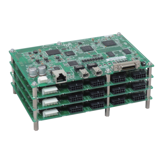
3 Specifications and Dimensional Drawings 3.2.4 Dimensional Drawings 3.2.4 Dimensional Drawings This section provides dimensional drawings. Dimensions in the dimensional drawings are in millimeters. (1) Type A01 SERVOPACK Board with Four Axes • Without Mounting Option Six studs (M3 female threads, effective screw depth: 4 mm) 16.6 30.5... - Page 53 3.2 SERVOPACKs Board with Eight Axes • Without Mounting Option Six studs (M3 female threads, effective screw depth: 4 mm) 16.6 16.6 47.1 • With Mounting Option Four, n5 (M4 mounting holes) 59.1 3-19...
- Page 54 3 Specifications and Dimensional Drawings 3.2.4 Dimensional Drawings Board with Twelve Axes • Without Mounting Option Six studs (M3 female threads, effective screw depth: 4 mm) 16.6 16.6 16.6 63.7 • With Mounting Option Four, n5 (M4 mounting holes) 75.7 3-20...
- Page 55 3.2 SERVOPACKs (2) Type A02 SERVOPACK 29.1 10.9 8-3.6 dia. 3-21...
- Page 56 Installation This section describes how to install servomotors and SERVOPACKs. 4.1 Servomotor Installation ........4-2 4.1.1 Servomotor Installation Environment .
-
Page 57: Servomotor Installation
4 Installation 4.1.1 Servomotor Installation Environment Servomotor Installation 4.1.1 Servomotor Installation Environment Surrounding air temperature: 0 to 40°C Surrounding air humidity: 80% RH or less (with no condensation) Altitude: 1, 000 m or less Vibration resistance: The servomotor will withstand the following vibration acceleration in three directions: vertical, side to side, and front to back. -
Page 58: Connecting Servomotor To Machine
4.1 Servomotor Installation 4.1.4 Connecting Servomotor to Machine The end of the motor shaft is coated with anticorrosive paint. Thoroughly remove the paint prior to installa- tion. Align the shaft of the servomotor with the shaft of the machine, and then couple the shafts. Install the servo- motor so that alignment accuracy falls within the following range. -
Page 59: Other Precautions
4 Installation 4.1.6 Other Precautions 4.1.6 Other Precautions (1) Cable Stress Do not bend or apply tension to the servomotor/encoder relay cable. Be especially careful to wire encoder cables so that they are not subject to stress because the core wires are very thin at only 0.2 or 0.3 mm ... - Page 60 4.1 Servomotor Installation • Interference between cables Avoid interference between cables. Interference limits the motion of flexible cable, which causes early disconnection. Keep enough distance between cables, or provide a partition when wiring. Connectors Observe the following precautions: • Make sure there is no foreign matters such as dust and metal chips in the connector before connecting. •...
-
Page 61: Servopack Installation
4 Installation 4.2.1 SERVOPACK Installation Environment SERVOPACK Installation 4.2.1 SERVOPACK Installation Environment temperature: 0 to 55°C Surrounding air humidity: 90% RH or less (with no condensation) Surrounding air Altitude: 1,000 m or less Vibration resistance: 49 m/s Note: The vibration resistance of a type A01 SERVOPACK with the mounting option is 4.9 m/s ... -
Page 62: Mounting The Servopack
4.2 SERVOPACK Installation 4.2.2 Mounting the SERVOPACK Use the following procedure to mount the SERVOPACK to the system. (1) Mounting a Type A01 SERVOPACK SERVOPACK without the Mounting Option Mount the SERVOPACK to the system with M3 screws according to the mounting positions of the six studs on the bottom of the SERVOPACK. -
Page 63: Mounting Orientation
4 Installation 4.2.3 Mounting Orientation (2) Mounting a Type A02 SERVOPACK Remove the spacers between the boards. Spacer Spacer Attach 8 studs (length: 5 mm or above) to the system to fit in the 8 holes in the control board. Align the control board with the studs, and attach 8 studs (length: 9 mm) in the 8 holes in the control board. -
Page 64: Emc Installation Conditions
The EMC installation conditions that are given in this section were used in passing the testing that was received by Yaskawa. The actual EMC level will depend on the actual device configuration, wiring, and other conditions. Because these products are built into a system, the user must implement EMC measures and con- firm compliance for the overall system. -
Page 65: Sgdv-Mda02E8M3A
4 Installation 4.3.2 SGDV-MDA02E8M3A 4.3.2 SGDV-MDA02E8M3A Shielded box 100 VAC Noise filter 24-VDC 48-VDC 24-VDC Host power power power controller supply supply supply 100 VAC Ferrite core Shielded box CN6A CN6B CN31 CN32 SGDV-MDA02E8M3A CN11... - Page 66 Wiring and Connections 5.1 Wiring the Main Circuit and Control Power Supplies ....5-2 5.1.1 Main Circuit Power Supply Terminals (CN32) and Control Power Supply Terminals (CN31) .
-
Page 67: Chapter 5 Wiring And Connections
5 Wiring and Connections 5.1.1 Main Circuit Power Supply Terminals (CN32) and Control Power Supply Terminals (CN31) Wiring the Main Circuit and Control Power Supplies This section gives the names and specifications of the main circuit power supply terminals and control power supply terminals. - Page 68 5.1 Wiring the Main Circuit and Control Power Supplies (2) Type A02 SERVOPACK CN31 CN32 The main circuit power supply terminals and control power supply terminals are circled in the figure. Connector No. Signal Pin No. Name Specification 1 to 4 Main circuit power supply input pin + 24 VDC -10% to +15% or 48 VDC -15% to +10%...
-
Page 69: Main Circuit And Control Power Supply Cables
5 Wiring and Connections 5.1.2 Main Circuit and Control Power Supply Cables 5.1.2 Main Circuit and Control Power Supply Cables This section provides the specifications of the main circuit power supply cable and control power supply cable. Cable Terminals Model Main Circuit Power Supply Cable L1, L2, –... - Page 70 5.1 Wiring the Main Circuit and Control Power Supplies Type A02 SERVOPACK • Main Circuit Power Supply Pins Connector Housing Contacts Manufacturer Main circuit power supply Cable side: VHR-10N, SVH-41T-P1.1 J.S.T. Mfg. Co., Ltd. connector SERVOPACK side: B10P-VH • Parts and Functions of the Main Circuit Power Supply Connector (CN32) Pin No.
- Page 71 5 Wiring and Connections 5.1.2 Main Circuit and Control Power Supply Cables (2) Control Power Supply Cable Specifications The control power supply cable specifications are given below. Control Power Supply Connector (CN31) Connector Housing Contacts Manufacturer Cable side: VHR-3N, Type A01 SERVOPACK side: Control power supply B3PS-VH,...
-
Page 72: Typical Main Circuit Wiring Example
5.1 Wiring the Main Circuit and Control Power Supplies 5.1.3 Typical Main Circuit Wiring Example Take the following points into consideration when designing the power ON sequence. • You must design the system to turn OFF the main circuit power supply when a servo alarm is detected. •... - Page 73 5 Wiring and Connections 5.1.3 Typical Main Circuit Wiring Example 2φ 100 VAC SERVOPACK Isolated AC/DC converter for main CN11 to circuit power supply CN32 1FLT (open) Isolated AC/DC converter for control circuit power supply CN31 Main circuit Main circuit power supply power supply 1QF: Molded-case circuit breaker...
-
Page 74: Power Losses
5.1 Wiring the Main Circuit and Control Power Supplies 5.1.4 Power Losses The following table shows the SERVOPACK’s power losses. (1) Main Circuit Power Supply of 24 VDC Main Circuit Control Circuit Total Power Remarks (e.g., SERVOPACK Model Power Loss [W] Power Loss [W] Loss [W] Conditions) -
Page 75: General Precautions For Wiring
5 Wiring and Connections 5.1.6 General Precautions for Wiring 5.1.6 General Precautions for Wiring • Always use a molded-case circuit breaker (1QF) or a fuse to protect the servo system from intersystem faults. • Install a ground fault detector. The SERVOPACK does not have a built-in protective circuit for grounding. To configure a safer system, install a ground fault detector against overloads and short-circuiting, or install a ground fault detector combined with a molded-case circuit breaker. -
Page 76: I/O Signal (Cn1) Connections
5.2 I/O Signal (CN1) Connections I/O Signal (CN1) Connections This section gives the names and functions of the I/O signal pins, as well as connection examples. Note: This information applies only to the SGDV-MD A01EM3A and SGDV-MD A02E8M3A01. 5.2.1 I/O Signal Names and Functions The I/O signals are used for the following functions. -
Page 77: I/O Signal Connector Specifications
5 Wiring and Connections 5.2.2 I/O Signal Connector Specifications 5.2.2 I/O Signal Connector Specifications This section gives the specifications of the I/O signal connector. (1) I/O Signal Connector Connector Housing Case Manufacturer Cable side: 10126-3000PE, I/O signal connector 10326-52A0-008 3M Japan Limited SERVOPACK side: 10226-62M2PL (2) I/O Signal Connector Pin Arrangement Pin No. -
Page 78: Example Of I/O Signal Connections
5.2 I/O Signal (CN1) Connections 5.2.3 Example of I/O Signal Connections The following diagram shows a typical connection example. Photocoupler output Max. operating voltage: 30 VDC Max. output current: 50 mA DC SERVOPACK Control power supply +24 V ∗ for sequence signal 4.7 kΩ... -
Page 79: Sequence Input Circuit
5 Wiring and Connections 5.2.4 Sequence Input Circuit 5.2.4 Sequence Input Circuit (1) Photocoupler Input Circuit CN1 connector pin 2 is described below. The sequence input circuit interface is connected through a relay or open-collector transistor circuit. When connecting through a relay, use a low-current relay. If a low-current relay is not used, a faulty contact may result. -
Page 80: Sequence Output Circuit
5.2 I/O Signal (CN1) Connections 5.2.5 Sequence Output Circuit The signal output circuit from the SERVOPACK is described below. Incorrect wiring or incorrect voltage application to the output circuit may cause short-cir- cuit. If a short-circuit occurs as a result of any of these causes, the holding brake will not work. -
Page 81: I/O Signal Assignments
5 Wiring and Connections 5.3.1 I/O Signal Setting Parameters I/O Signal Assignments You can assign the overtravel signals, homing deceleration switch, external latch, and brake output signals to the CN1 sequence I/O signals. 5.3.1 I/O Signal Setting Parameters Parameter to Set Assigned Signal Function Sequence Input Signal Pin Numbers Pn590... - Page 82 5.3 I/O Signal Assignments (2) Input Signal Pin Assignments Use parameters Pn590 to Pn595 to assign I/O signal connector pins 5 and 7 to 13. Parameter Meaning Pin No. When Enabled Classification n.0 Selects sequence input signal /SI-0. After restart Setup n.1 Selects sequence input signal /SI-1.
-
Page 83: Wiring Mechatrolink-Iii Communications
5 Wiring and Connections Wiring MECHATROLINK-III Communications The following diagram shows an example of connections between a host controller and a SERVOPACK using. MECHATROLINK-III communications cables (CN6A, CN6B). SVC-01 MP2300 YASKAWA STOP CNFG TEST OFF ON M-I/II BATTERY CPU I/O... -
Page 84: Connecting The Servomotor And Encoder
5.5 Connecting the Servomotor and Encoder Connecting the Servomotor and Encoder This section describes the connection signal (CN11 to CN18) names and functions and cable specifications for the servomotor and encoder. It also provides connection examples. 5.5.1 Names and Functions of Servomotor and Encoder Connection Signals This section provides the names and functions of servomotor and encoder connection signals (CN11 to CN1). -
Page 85: Servomotor/Encoder Relay Cable Specifications
5 Wiring and Connections 5.5.2 Servomotor/Encoder Relay Cable Specifications (2) Type A02 SERVOPACK CN18 CN17 CN16 CN15 CN14 CN13 CN12 CN11 Connector No. Symbol Pin No. Name Specification Differential serial signal + Encoder differential serial signal input Differential serial signal - Encoder power supply + Encoder power supply (+5 V) Encoder power supply -... -
Page 86: Servomotor And Encoder Connection Examples
5.5 Connecting the Servomotor and Encoder 5.5.3 Servomotor and Encoder Connection Examples This section provides examples of connections between the SERVOPACK and encoder. (1) Using as an Incremental Encoder SERVOPACK Incremental encoder CN11 to CN1 PG5V PG0V Connector shell (Shell) Shielded wire Shielded wire ∗1. -
Page 87: Battery Replacement
5.5.4 Battery Replacement • If you use the encoder as an absolute encoder, use one of the encoder cables with a battery case specified by Yaskawa. Refer to 2.4.2 Servomotor/Encoder Relay Cables for the model numbers of the cables. 5.5.4 Battery Replacement If the battery voltage drops to approximately 2.7 V or less, an absolute encoder battery error alarm (A.830) or... - Page 88 5.5 Connecting the Servomotor and Encoder (1) Battery Replacement Procedure Turn ON the control power supply of the SERVOPACK only. Open the battery case cover. Open the cover. To the SERVOPACK Remove the old battery and mount the new JZSP-BA01 battery as shown below. Encoder Cable To the SERVOPACK B Mount the JZSP-BA01 battery.
-
Page 89: Noise Control And Measures For Harmonic Suppression
5 Wiring and Connections 5.6.1 Wiring for Noise Control Noise Control and Measures for Harmonic Suppression This section describes the wiring for noise control and the DC reactor for harmonic suppression. 5.6.1 Wiring for Noise Control • Because the SERVOPACK is designed as an industrial device, it provides no mecha- nism to prevent noise interference. -
Page 90: Precautions On Connecting Noise Filter
5.6 Noise Control and Measures for Harmonic Suppression (2) Correct Grounding Take the following grounding measures to prevent the malfunction due to noise. Grounding the Motor Frame If the servomotor is grounded through the machine, switching noise current will flow from the main circuit of the SERVOPACK through the floating capacitance of the servomotor. - Page 91 5 Wiring and Connections 5.6.2 Precautions on Connecting Noise Filter Separate the noise filter ground wire from the output lines. Do not accommodate the noise filter ground wire, output lines and other signal lines in the same duct or bundle them together. Incorrect Correct Noise...
-
Page 92: Sigmawin
SigmaWin+ 6.1 SigmaWin+ ..........6-2 6.2 Preparing SigmaWin+ . -
Page 93: Preparing Sigmawin
SigmaWin+ is a software application that can be used to view SERVOPACK status, set parameters, and per- form setup tuning. Preparing SigmaWin+ Install SigmaWin+ after downloading the software application from the following Yaskawa website. SigmaWin+ software version 5.62 or higher is required for the Σ-V-MD SERVOPACKs. Connecting a PC with SigmaWin+ Use Ethernet to connect the computer where the SigmaWin+ is installed to the SERVOPACK. -
Page 94: Setting The Ip Address In The Servopack
6.3 Connecting a PC with SigmaWin+ Select Internet Protocol (TCP/IP) and click Properties. The following dialog box appears. Select the Use the following IP address option, enter any IP address in the IP address box and enter "255 255 255 0" in the Subnet mask box. Click OK to close the dialog box. -
Page 95: Initializing The Communications Settings
6 SigmaWin+ 6.3.3 Initializing the Communications Settings 6.3.3 Initializing the Communications Settings You use the communications setting switch (S1) to restore the Ethernet and MECHATROLINK-III communi- cations settings to their factory settings. • Type A01 SERVOPACK CN31 CN32 • Type A02 SERVOPACK Communications setting switch (S1) Pin on S1 Function... -
Page 96: Starting And Operating The Sigmawin
6.4 Starting and Operating the SigmaWin+ Starting and Operating the SigmaWin+ Use the following procedure to display the main window of the SigmaWin+. Connect a SERVOPACK to a computer which has SigmaWin+ installed. For the connection method, refer to the figure in 1.2 Examples of Servo System Configurations. Turn on the SERVOPACK. - Page 97 6 SigmaWin+ Click Search. A message will appear first to indicate that a search is being carried out, and then the search results will be shown in the Connect window. Select the SERVOPACK to be connected. Click Connect. The SigmaWin+ main window will appear.
-
Page 98: Parameters (Pn)
6.5 Parameters (Pn) Parameters (Pn) This section describes the classifications, methods of notation, and settings for parameters given in this man- ual. 6.5.1 Parameter Classification Parameters of the Σ-V Series SERVOPACK are classified into two types of parameters. One type of parame- ters is required for setting up the basic conditions for operation and the other type is required for tuning param- eters that are required to adjust servomotor characteristics Classification... -
Page 99: Setting Parameters
6 SigmaWin+ 6.5.3 Setting Parameters 6.5.3 Setting Parameters There are two ways to set parameters. These are as follows: • Using the Parameter Editing dialog box • Using the Online Parameter Editing dialog box These methods are described below. (1) Using the Parameter Editing Dialog Box In the SigmaWin+ main window, click Parameters - Edit Parameters. - Page 100 6.5 Parameters (Pn) Click Edit. The Edit box for the selected parameter will appear. Change the value of the parameter. <For parameters for numeric settings> Enter the value to be set. <For parameters for selecting functions> Click the arrow to open the setting list for each digit and select one item in each list. Click OK.
- Page 101 6 SigmaWin+ 6.5.3 Setting Parameters (2) Using the Online Parameter Editing Dialog Box • Values edited in the Online Parameter Editing dialog box are immediately changed in the SERVOPACK. • If the power to the SERVOPACK is turned OFF or the communication between the SERVOPACK and the SigmaWin+ is interrupted while editing parameters online, the edited values will not be saved in the SERVOPACK.
- Page 102 6.5 Parameters (Pn) Click one of the Set buttons located on the right of the parameter list. The Parameters list box will appear. Select a parameter to edit, and then click OK. The Set Parameters box will appear again. Click OK. The Online Parameter Editing dialog box will appear again.
-
Page 103: Monitor Operations
6 SigmaWin+ Monitor Operations Use the following procedure to monitor values. Select Monitor - Monitor from the menu bar of the SigmaWin+ main window. The following window appears. The items that you can monitor are displayed. Select the check boxes on the left side of the items to monitor. The current values are displayed in the value columns. - Page 104 Operation 7.1 MECHATROLINK-III Communications Settings ....7-2 7.1.1 Setting the MECHATROLINK-III Station Address ......7-2 7.1.2 Setting the MECHATROLINK-III Axis Addresses .
-
Page 105: Mechatrolink-Iii Communications Settings
7 Operation 7.1.1 Setting the MECHATROLINK-III Station Address MECHATROLINK-III Communications Settings This section describes the switch settings necessary for MECHATROLINK-III communications. 7.1.1 Setting the MECHATROLINK-III Station Address Set the MECHATROLINK-III station address in Pn880. Station Address Setting Speed Position Torque ... -
Page 106: Setting The Number Of Transmission Bytes For Mechatrolink-Iii
7.1 MECHATROLINK-III Communications Settings • Type A02 SERVOPACK SGDV-MDA02E8M3A Axis 1 Axis 2 Axis 3 Axis 4 Axis 5 Axis 6 Axis 7 Axis 8 CN11 CN12 CN13 CN14 CN15 CN16 CN17 CN18 used. used. Pn010 Pn011 Pn012 Pn013 Pn014 Pn015 Pn016 Pn017 Factory-set axis address settings Pn016 Pn017... -
Page 107: Mechatrolink-Iii Commands
7 Operation 7.3.1 Servomotor Rotation Direction MECHATROLINK-III Commands Σ Refer to the -V-MD Series User’s Manual MECHATROLINK-III Standard Servo Profile Commands (Manual No.: SIEP S800001 03) for details on MECHATROLINK-III commands. Basic Functions Settings This section describes how to set the basic functions for operation. 7.3.1 Servomotor Rotation Direction The servomotor rotation direction can be reversed with parameter Pn000.0 without changing the polarity of... -
Page 108: Overtravel
7.3 Basic Functions Settings 7.3.2 Overtravel The overtravel limit function forces movable machine parts to stop if they exceed the allowable range of motion and turn ON a limit switch. For rotating application such as disc table and conveyor, overtravel function is not necessary. In such a case, no wiring for overtravel input signals is required. - Page 109 7 Operation 7.3.2 Overtravel (2) Overtravel Function Setting You can use Pn590 and Pn591 to enable or disable the overtravel function. If the overtravel function is not used, no wiring for overtravel input signals will be required. Parameter Meaning When Enabled Classification n.0...
- Page 110 7.3 Basic Functions Settings When Servomotor Stopping Method is Set to Decelerate to Stop Emergency stop torque can be set with Pn406 Emergency Stop Torque Speed Position Torque Classification Pn406 Setting Range Setting Unit Factory Setting When Enabled 0 to 800 800% Immediately...
- Page 111 7 Operation 7.3.2 Overtravel CAUTION • The overtravel warning function only detects warnings. It does not affect on stopping for overtravel or motion operations at the host controller. The next step (e.g., the next motion or other command) can be executed even if an overtravel warning exists.
-
Page 112: Software Limit Settings
7.3 Basic Functions Settings 7.3.3 Software Limit Settings Software limits are used to force the moving part of the machine to stop if it exceeds a preset limit value. If a reference to a target position that exceeds a software limit is given during position control, the target position in the SERVOPACK is clamped to the value of the software limit and positioning is completed. -
Page 113: Holding Brakes
7 Operation 7.3.4 Holding Brakes 7.3.4 Holding Brakes A holding brake is a brake used to hold the position of the movable part of the machine when the SERVO- PACK is turned OFF so that movable part does not move due to gravity or external forces. Holding brakes are built into servomotors with brakes. - Page 114 7.3 Basic Functions Settings (1) Wiring Example Use the brake signal (/BK) and the brake power supply to form a brake ON/OFF circuit. The following dia- gram shows a standard wiring example. The timing can be easily set using the brake signal (/BK). Servomotor Isolated with holding...
- Page 115 7 Operation 7.3.4 Holding Brakes (2) Brake Signal (/BK) Setting This output signal controls the brake. The /BK signal turns OFF (applies the brake) when an alarm is detected or the SV_OFF command is received. The brake OFF timing can be adjusted with Pn506. Connector Type Name...
- Page 116 7.3 Basic Functions Settings (4) Brake Signal (/BK) Output Timing during Servomotor Rotation If an alarm occurs while the servomotor is rotating, the servomotor will come to a stop and the brake signal (/BK) will be turned OFF. The timing of brake signal (/BK) output can be adjusted by setting the brake refer- ence output speed level (Pn507) and the waiting time for brake signal when motor running (Pn508).
-
Page 117: Stopping Servomotors After Sv_Off Command Or Alarm Occurrence
7 Operation 7.3.5 Stopping Servomotors after SV_OFF Command or Alarm Occurrence 7.3.5 Stopping Servomotors after SV_OFF Command or Alarm Occurrence The servomotor stopping method can be selected after the SV_OFF command is received or an alarm occurs. • The elements in the SERVOPACK will deteriorate if turning the power supply ON and OFF or starting and stopping the servomotor during the servo ON status while there is a reference input. -
Page 118: Setting Motor Overload Detection Level
7.3 Basic Functions Settings 7.3.6 Setting Motor Overload Detection Level In this SERVOPACK, the detection timing of the warnings and alarms can be changed by changing how to detect an overload warning (A.910) and overload (low load) alarm (A.720). The overload characteristics and the detection level of the overload (high load) alarm (A.710) cannot be changed. - Page 119 7 Operation 7.3.6 Setting Motor Overload Detection Level (2) Changing Detection Timing of Overload (Low Load) Alarm (A.720) An overload (low load) alarm (A.720) can be detected earlier to protect the servomotor from overloading. The time required to detect an overload alarm can be shortened by using the derated motor base current obtained with the following equation.
-
Page 120: Trial Operation
7.4 Trial Operation Trial Operation This section describes a trial operation using MECHATROLINK-III communications. 7.4.1 Inspection and Checking before Trial Operation To ensure safe and correct trial operation, inspect and check the following items before starting trial operation. (1) Servomotors Inspect and check the following items, and take appropriate measures before performing trial operation if any problem exists. -
Page 121: Trial Operation Via Mechatrolink-Iii
7 Operation 7.4.2 Trial Operation via MECHATROLINK-III 7.4.2 Trial Operation via MECHATROLINK-III The following table provides the procedures for trial operation via MECHATROLINK-III. Step Description Reference Confirm that the wiring is correct, and then connect the I/O signal con- Chapter 5 Wiring and Connections nector (CN1 connector). -
Page 122: Electronic Gear
7.4 Trial Operation 7.4.3 Electronic Gear The electronic gear enables the workpiece travel distance per reference unit input from the host controller. The minimum unit of the position data moving a load is called a reference unit. The section indicates the difference between using and not using an electronic gear when a workpiece is moved 10 mm in the following configuration. - Page 123 7 Operation 7.4.3 Electronic Gear (1) Electronic Gear Ratio Set the electronic gear ratio using PnA42 and PnA44. Electronic Gear Ratio (Numerator) Position Classification PnA42 Setting Range Setting Unit Factory Setting When Enabled 1 to 1073741824 After restart Setup Electronic Gear Ratio (Denominator) Position Classification PnA44...
- Page 124 7.4 Trial Operation (2) Electronic Gear Ratio Setting Examples The following examples show electronic gear ratio settings for different load configurations. Load Configuration Ball Screw Disc Table Belt and Pulley Reference unit: 0.001 mm Reference unit: 0.01 Reference unit: 0.005 mm Step Operation Load shaft...
-
Page 125: Limiting Torque
7 Operation 7.5.1 Internal Torque Limit Limiting Torque The SERVOPACK provides the following three methods for limiting output torque to protect the machine. Reference Limiting Method Description Section 7.5.1 Internal Internal torque limit Always limits torque by setting the parameter. Torque Limit Torque limit with the com- Limits torque by using the command data (TLIM) for torque lim-... -
Page 126: Absolute Encoder Setting
7.6 Absolute Encoder Setting Absolute Encoder Setting If using an absolute encoder, a system to detect the absolute position can be designed for use with the host controller. As a result, an operation can be performed without a zero point return operation immediately after the power is turned ON. - Page 127 7 Operation 7.6.1 Absolute Encoder Setup Make sure that the motor power is OFF. In the SigmaWin+ main window, click Setup – Set Absolute Encoder – Reset Absolute Encoder. Supplemental Information If you are using more than one axis, the Axis Selection Dialog Box is displayed. Follow the instructions in the Axis Selection Dialog Box to select the axis to adjust before you continue.
- Page 128 7.6 Absolute Encoder Setting Click Continue to set up the encoder. <If Setup is Unsuccessful> If setting up is attempted with the servo ON, a reset conditions error occurs, and the processing is aborted. Click OK to return to the main window. <If Setup Completes Normally>...
-
Page 129: Multiturn Limit Setting
7 Operation 7.6.2 Multiturn Limit Setting 7.6.2 Multiturn Limit Setting The multiturn limit setting is used in position control applications for a turntable or other rotating device. For example, consider a machine that moves the turntable in the following diagram in only one direction. Turntable Gear Servomotor... - Page 130 7.6 Absolute Encoder Setting Set the vale, the desired rotrational amount -1, to Pn205. Factory Setting Other Setting +32767 Reverse PnA48 setting value Forward Forward Reverse Rotational data Rotational data Motor rotations Motor rotations -32768 7-27...
-
Page 131: Multiturn Limit Disagreement Alarm (A.cc0)
7 Operation 7.6.3 Multiturn Limit Disagreement Alarm (A.CC0) 7.6.3 Multiturn Limit Disagreement Alarm (A.CC0) When the multiturn limit set value is changed with parameter PnA48, a multiturn limit disagreement alarm (A.CC0) will be displayed because the value differs from that of the encoder. Alarm Alarm Name Alarm Output... - Page 132 7.6 Absolute Encoder Setting Change the setting to the desired number of revolutions. To save the settings, click Writing into the Servopack. A warning message will appear. Click OK and the settings are changed to the new ones. Restart the SERVOPACK. Because only the settings for the SERVOPACK were made, the settings for the servomotor are still incomplete and an alarm occurs.
-
Page 133: Absolute Encoder Origin Offset
7 Operation 7.6.4 Absolute Encoder Origin Offset Click Continue. The Multi-Turn Limit Setting box will appear. To change the settings, click Re-Change. To save the settings, click Writing into the Motor. A warning message will appear Click OK. 7.6.4 Absolute Encoder Origin Offset If using the absolute encoder, the positions of the encoder and the offset of the machine coordinate system (APOS) can be set. - Page 134 Adjustments 8.1 Type of Adjustments and Basic Adjustment Procedure ....8-3 8.1.1 Adjustments ............8-3 8.1.2 Basic Adjustment Procedure .
- Page 135 8 Adjustments 8.8 Additional Adjustment Function ....... 8-77 8.8.1 Switching Gain Settings ..........8-77 8.8.2 Manual Adjustment of Friction Compensation .
-
Page 136: Chapter 8 Adjustments
8.1 Type of Adjustments and Basic Adjustment Procedure Type of Adjustments and Basic Adjustment Procedure This section describes type of adjustments and the basic adjustment procedure. 8.1.1 Adjustments Adjustments (tuning) are performed to optimize the responsiveness of the SERVOPACK. The responsiveness is determined by the servo gain that is set in the SERVOPACK. The servo gain is set using a combination of parameters, such as speed loop gain, position loop gain, filters, friction compensation, and moment of inertia ratio. -
Page 137: Basic Adjustment Procedure
8 Adjustments 8.1.2 Basic Adjustment Procedure 8.1.2 Basic Adjustment Procedure The basic adjustment procedure is shown in the following flowchart. Make suitable adjustments considering the conditions and operating requirements of the machine Start adjusting servo gain. (1) Adjust using Tuning-less Function. Runs the servomotor without any adjustments. -
Page 138: Monitoring Operation During Adjustment
8.1 Type of Adjustments and Basic Adjustment Procedure 8.1.3 Monitoring Operation during Adjustment While adjusting the servo gain, always monitor the operating status of the machine and the signal waveform. Use data tracing from the SigmaWin+ to monitor signal waveforms from the SERVOPACK. This section describes data tracing from the SigmaWin+. - Page 139 8 Adjustments 8.1.3 Monitoring Operation during Adjustment (2) Trace Setting In the Trace main window, click SETUP, and the Trace Setting box appears. Select the objects and conditions for the trace. The settings from the previous trace, if any, are displayed. Refer to the SigmaWin+ Online Manual for detailed trace settings.
- Page 140 8.1 Type of Adjustments and Basic Adjustment Procedure Trigger Setting A trigger is a device for designating the timing of data access. For example, if you set the condition that the speed feedback exceeds 100 min , you can check detailed servo operation after the point where that condition is satisfied.
- Page 141 8 Adjustments 8.1.3 Monitoring Operation during Adjustment Rising Edge: The trigger is detected when the trigger object data rises from below the trigger level to above the trigger level. When the change is from LO to HI in I/O Falling Edge: The trigger is detected when the trigger object data falls from above the trigger level to below the trigger level.
- Page 142 8.1 Type of Adjustments and Basic Adjustment Procedure Starting on a Trigger Click Start in the Trace main window, and the SigmaWin+ will wait for the trigger. The window below appears while waiting for the trigger. Dialog Box While Waiting for a Trigger...
- Page 143 8 Adjustments 8.1.3 Monitoring Operation during Adjustment Transferring Data The message remains until the set trigger conditions are met. Click Stop to stop waiting for the trigger Dialog Box While Transferring Data Once the trigger condition is satisfied, the SERVOPACK starts transferring data to the SigmaWin+. When the data transfer is completed, the Trace main window appears.
- Page 144 8.1 Type of Adjustments and Basic Adjustment Procedure (4) Displaying Trace Results This Trace main window displays a graph based on the trace settings. Dialog Box Showing Trace Results 8-11...
-
Page 145: Safety Precautions On Adjustment Of Servo Gains
8 Adjustments 8.1.4 Safety Precautions on Adjustment of Servo Gains 8.1.4 Safety Precautions on Adjustment of Servo Gains CAUTION • If adjusting the servo gains, observe the following precautions. • Do not touch the rotating section of the servomotor while power is being supplied to the motor. •... - Page 146 8.1 Type of Adjustments and Basic Adjustment Procedure The following example outlines how the maximum limit for position deviation is calculated. These conditions apply. • Maximum speed = 6000 • Encoder resolution = 131072 (17 bits) • PnAC6 = 400 PnA44 •...
-
Page 147: Tuning-Less Function
8 Adjustments 8.2.1 Tuning-less Function Tuning-less Function The tuning-less function is enabled in the factory settings. If resonance is generated or excessive vibration occurs, refer to 8.2.2 Tuning-less Levels Setting Procedure and change the set value of Pn170.2 for the rigidity level and the set value in Pn170.3 for the load level. - Page 148 8.2 Tuning-less Function (3) Automatically Setting the Notch Filter Usually, set this function to Auto Setting. (The notch filter is factory-set to Auto Setting.) If this function is set to Auto Setting, vibration will be detected automatically and the notch filter will be set when the tuning-less function is enabled.
-
Page 149: Tuning-Less Levels Setting Procedure
8 Adjustments 8.2.2 Tuning-less Levels Setting Procedure 8.2.2 Tuning-less Levels Setting Procedure CAUTION • To ensure safety, perform the tuning-less function in a state where the SERVOPACK can come to an emergency stop at any time. The procedure to use the tuning-less function is given below. The SigmaWin+ is required to execute this function. - Page 150 8.2 Tuning-less Function Select Pn170 in the Parameter Editing dialog box. If Pn170 cannot be seen in the Parameter Editing dialog box, click the arrows to view the parameter. Click Edit. The Edit box for Pn170 will appear. 8-17...
- Page 151 8 Adjustments 8.2.2 Tuning-less Levels Setting Procedure For 3rd digit, select one of the load levels in the Tuning-less Load Level list. • If the response waveform results in overshooting or if the load moment of inertia exceeds the allowable level, select 2: Tuning-less Load Level 2.
-
Page 152: Related Parameters
8.2 Tuning-less Function Parameters Disabled by Tuning-less Function When the tuning-less function is enabled in the factory settings, the settings of these parameters are not avail- able: PnAC2, PnAC4, PnAC6, Pn103, Pn104, Pn105, Pn106, Pn160, Pn139 and Pn408. These gain-related parameters, however, may become effective depending on the executing conditions of the functions specified in the following table. -
Page 153: Advanced Autotuning
8 Adjustments 8.3.1 Advanced Autotuning Advanced Autotuning This section describes the adjustment using advanced autotuning • Advanced autotuning starts adjustments based on the set speed loop gain (PnAC2). Therefore, precise adjustments cannot be made if there is vibration when starting adjustments. - Page 154 8.3 Advanced Autotuning Movement Speed Rated motor speed t: time Reference Rated motor Response speed Execute advanced autotuning Rated motor after a JOG operation to torque: move the position to ensure a Approx. 100% suitable movement range. SERVOPACK t: time Rated motor torque:...
-
Page 155: Advanced Autotuning Procedure
8 Adjustments 8.3.2 Advanced Autotuning Procedure • The mode switch is used. Note:If a setting is made for calculating the moment of inertia, the mode switch function will be disabled while the moment of inertia is being calculated. At that time, PI control will be used. The mode switch function will be enabled after calculating the moment of inertia. - Page 156 8.3 Advanced Autotuning In the SigmaWin+ main window, click Tuning – Tuning. <Supplemental Information> If you are using more than one axis, the Axis Selection Dialog Box is displayed. Follow the instructions in the Axis Selection Dialog Box to select the axis to adjust before you continue. The following window will appear.
- Page 157 8 Adjustments 8.3.2 Advanced Autotuning Procedure Click Execute. The following window will appear. Speed Loop Setting Set the speed loop gain and integral time constant. If the response of the speed loop is poor, the moment of inertia (mass) ratio cannot be measured accu- rately.
- Page 158 8.3 Advanced Autotuning Confirm Click Confirm to view the driving pattern Detailed Setting Create the reference pattern for setting the moment of inertia (mass) by changing the values with the slider or by directly entering the values. Next Click Next to view the Reference Transmission box. Cancel Click Cancel to return to the main window without changing the conditions.
- Page 159 8 Adjustments 8.3.2 Advanced Autotuning Procedure Click Next. The following window will appear. Start Click to Start to transfer the reference conditions to the SERVOPACK. A progress bar displays the progress status of the transfer. Cancel The Cancel button is available only during the transfer to the SERVOPACK.
- Page 160 8.3 Advanced Autotuning Click Servo On. Click Forward to take measurements by turning (moving) the motor forward. After the measurements and the data transmission are finished, the following window will appear. Click Reverse to take measurements by turning (moving) the motor in reverse. After the measurements and the data transmission are finished, the following window will appear.
- Page 161 8 Adjustments 8.3.2 Advanced Autotuning Procedure Click Next. The following window will appear. Identified Moment of Inertia (Mass) Ratio Displays the moment of inertia (mass) ratio calculated in the operation/measurement. Writing Results Click Writing Results to assign the value displayed in the identified moment of inertia (mass) ratio to SERVOPACK parameter Pn103.
- Page 162 8.3 Advanced Autotuning After confirming that the value displayed in the identified moment of inertia (mass) ratio and the value displayed in the Pn103: Moment of Inertia Ratio are the same, click Finish. The following window will appear. Click OK. The following window will appear Click Execute to save the change of Pn103 (Moment of Inertia (Mass) Ratio) to SERVOPACK.
- Page 163 8 Adjustments 8.3.2 Advanced Autotuning Procedure (2) Procedure for Autotuning without a Host Reference Use the following procedure to execute autotuning without a host reference. Select the No reference input option under Reference input from host controller in the Tuning main window, and then click Autotuning. The following window will appear <Supplemental Information>...
- Page 164 8.3 Advanced Autotuning Select whether or not to use the load moment of inertia (load mass) identification from the Switching the load moment of inertia (load mass) identification box, the mode from the Mode selection box, the mechanism from the Mechanism selection box, and enter the moving distance.
- Page 165 8 Adjustments 8.3.2 Advanced Autotuning Procedure After confirming the safety of the area adjoining the drive unit, click Yes. The motor will start rotating and tuning will start. Vibration generated during tuning is automatically detected, and the optimum setting for the detected vibration will be made.
- Page 166 8.3 Advanced Autotuning When an Error Occurs Error Probable Cause Corrective Actions • Increase the set value for PnACC. • Change the setting of the mode selection The gain adjustment was Machine vibration is occurring or the posi- from 2 to 3. not successfully tioning completed signal is not stable when •...
- Page 167 8 Adjustments 8.3.2 Advanced Autotuning Procedure Related Functions on Advanced Autotuning Notch Filter Usually, set this function to Auto Setting. (The notch filter is factory-set to Auto Setting.) If this function is set to Auto Setting, vibration will be detected automatically during advanced autotuning and the notch filter will be set.
- Page 168 8.3 Advanced Autotuning Friction Compensation This function compensates for changes in the following conditions. • Changes in the viscous resistance of the lubricant, such as the grease, on the sliding parts of the machine • Changes in the friction resistance resulting from variations in the machine assembly •...
-
Page 169: Related Parameters
8 Adjustments 8.3.3 Related Parameters 8.3.3 Related Parameters The following parameters are either referenced or automatically changed during execution of advanced auto- tuning. Do not change the settings of these parameters from the SigmaWin+ during execution of advanced autotuning. Parameter Name Automatic changes PnAC2... -
Page 170: Advanced Autotuning By Reference
8.4 Advanced Autotuning by Reference Advanced Autotuning by Reference Adjustments with advanced autotuning by reference are described below. • Advanced autotuning by reference starts adjustments based on the set speed loop gain (PnAC2). Therefore, precise adjustments cannot be made if there is vibration when starting adjustments. - Page 171 8 Adjustments 8.4.1 Advanced Autotuning by Reference (1) Preparation The following conditions must be met to perform advanced autotuning by reference. • The SERVOPACK must be in Servo Ready status • There must be no overtravel. • The servomotor power must be OFF. •...
-
Page 172: Advanced Autotuning By Reference Procedure
8.4 Advanced Autotuning by Reference 8.4.2 Advanced Autotuning by Reference Procedure The following procedure is used for advanced autotuning by reference. Always set the moment of inertia ratio before you execute autotuning with a host reference. CAUTION • If you use phase control with an MP2000-series Controller, set the mode selection to 1. If the mode selec- tion is set to 2 or 3, correct phase control may not be possible. - Page 173 8 Adjustments 8.4.2 Advanced Autotuning by Reference Procedure Click OK. The following window will appear. Select the Position reference input option under Reference input from host controller in the Tuning main window, and then click Autotuning. The following window will appear. 8-40...
- Page 174 8.4 Advanced Autotuning by Reference Select the mode from the Mode selection combo box and the mechanism from Mechanism selection combo box, and then click Next. When the Start tuning using the default settings. check box is selected in the Autotuning-Setting Con- ditions box, tuning will be executed using tuning parameters set to the default value Click Yes.
- Page 175 8 Adjustments 8.4.2 Advanced Autotuning by Reference Procedure Turn the servo on and then input the reference from the host controller. Click Start tuning. After confirming the safety of the area adjoining the drive unit, click Yes. The motor will start rotating and tuning will start. Vibration generated during tuning is automatically detected, and the optimum setting for the detected vibration will be made.
- Page 176 8.4 Advanced Autotuning by Reference When an Error Occurs Error Probable Cause Corrective Actions • Increase the set value for PnACC. • Change the setting of the mode selection The gain adjustment Machine vibration is occurring or position- from 2 to 3. was not successfully ing completion is not stable when the servo- •...
- Page 177 8 Adjustments 8.4.2 Advanced Autotuning by Reference Procedure Vibration Suppression The vibration suppression function suppresses transitional vibration at frequency as low as 1 to 100 Hz that is generated mainly when positioning if the machine stand vibrates. Usually, set this function to Auto Setting. (The vibration suppression function is factory-set to Auto Setting.) When you set this function to Auto Setting, vibration will be automatically detected during autotuning with a host reference and vibration suppression will be automatically adjusted and set.
-
Page 178: Related Parameters
8.4 Advanced Autotuning by Reference 8.4.3 Related Parameters The following parameters are either referenced or automatically changed during execution of advanced auto- tuning by reference. Do not change the settings of these parameters from the SigmaWin+ during execution of advanced autotuning by reference. -
Page 179: One-Parameter Tuning
8 Adjustments 8.5.1 One-parameter Tuning One-parameter Tuning Adjustments with one-parameter tuning are described below. 8.5.1 One-parameter Tuning One-parameter tuning is used to manually make tuning level adjustments during operation with a position ref- erence or speed reference input from the host controller. The following are tuned automatically. - Page 180 8.5 One-parameter Tuning (1) Procedure for Custom Tuning Use the following procedure to execute custom tuning when the tuning mode is set to 0 (set servo gains with priority given to stability). WARNING Be sure to carefully read the SigmaWin+ Operation Manual before executing this function. Special care must be taken for the following.
- Page 181 8 Adjustments 8.5.2 One-parameter Tuning Procedure Click Execute. The following window will appear <Supplement> If the following window will appear, click OK and confirm that the correct moment of inertia ratio in Pn103 is set by using the Moment of Inertia (Mass) Setting window. Click Advanced adjustment.
- Page 182 8.5 One-parameter Tuning Click Custom tuning. The following box will appear. The tuning modes that can be selected will vary according to the SERVOPACK setting. Select the tuning mode from the Tuning mode box and the mechanism from the Mechanism selection box, and then click Next.
- Page 183 8 Adjustments 8.5.2 One-parameter Tuning Procedure Enter the correct moment of inertia ratio and then click Next. The following window will appear. Turn the servo on and then input the reference from the host controller. Click Start tuning. 8-50...
- Page 184 8.5 One-parameter Tuning Change the tuning level by clicking the setting arrows. Continue to raise the level until an overshoot occurs. Note:The set feedforward level will not be applied until the Positioning Completion signal is output. The notch filter/anti-resonance control auto setting function, the anti-resonance control adjustment func- tion, or autotuning by reference can be used as required.
- Page 185 8 Adjustments 8.5.2 One-parameter Tuning Procedure Use the following procedure to execute custom tuning when the tuning mode is set to 2 (set servo gains with priority given to positioning application). Click Advanced adjustment in the Tuning main window, and then click Custom tuning in the Tuning box that will appear.
- Page 186 8.5 One-parameter Tuning Click Next. The Custom Tuning - Adjust box will appear. Turn the servo on and input the reference from the host controller. Then, click Start tuning to begin tuning. 8-53...
- Page 187 8 Adjustments 8.5.2 One-parameter Tuning Procedure Change the feed forward level by clicking the setting arrows. Continue to raise the level until an overshoot occurs. <Supplemental Information> 1. The feed forward level is not applied until the positioning completed signal is output. 2.
- Page 188 8.5 One-parameter Tuning Repeat steps 5 and 6 to continue tuning. Supplemental Information 1. The notch filter/anti-resonance control auto setting function, the anti-resonance control adjustment function, the vibration suppression function, or autotuning by reference can be used as required. 2. To reset to the original settings and status, click Back. When tuning is complete, click Completed.
- Page 189 8 Adjustments 8.5.2 One-parameter Tuning Procedure Functions To Suppress Vibration • Notch Filter/Anti-resonance Control Adjustment Auto Setting Function For vibration frequencies above 1,000 Hz when servo gains are increased, the notch filter auto setting function provides effective suppression. For vibration frequencies between 100 and 1,000 Hz, the anti-resonance con- trol adjustment auto setting function is effective.
- Page 190 8.5 One-parameter Tuning (2) Related Functions on One-parameter Tuning This section describes functions related to one-parameter tuning. Notch Filter Usually, set this function to Auto Setting. (The notch filter is factory-set to Auto Setting.) When you set this function to Auto Setting, vibration will be automatically detected during custom tuning with a host reference and the notch filter will be adjusted.
- Page 191 8 Adjustments 8.5.2 One-parameter Tuning Procedure Feedforward If Model Following Control Related Switch (Pn140) is set to the factory setting and the tuning mode is set to 2 or 3 when custom tuning is executed, the feedforward gain (PnAC8), speed feedforward (VFF) input, and torque feedforward (TFF) input will be disabled.
-
Page 192: One-Parameter Tuning Example
8.5 One-parameter Tuning 8.5.3 One-parameter Tuning Example This section provides a tuning example when the tuning mode is set to 2 or 3. This mode is used to reduce positioning time. Step Measuring Instrument Display Example Operation Position error Measure the positioning time after setting the moment of iner- tia ratio (Pn103) correctly. -
Page 193: Related Parameters
8 Adjustments 8.5.4 Related Parameters 8.5.4 Related Parameters The following parameters are either referenced or automatically changed during execution of one-parameter tuning. Do not change the settings of these parameters from the SigmaWin+ during execution of one-parameter tun- ing. Parameter Name Automatic changes PnAC2... -
Page 194: Anti-Resonance Control Adjustment Function
8.6 Anti-Resonance Control Adjustment Function Anti-Resonance Control Adjustment Function This section describes the anti-resonance control adjustment function. 8.6.1 Anti-Resonance Control Adjustment Function The anti-resonance control adjustment function increases the effectiveness of the vibration suppression after one-parameter tuning. This function is effective in supporting anti-resonance control adjustment if the vibra- tion frequencies are from 100 to 1000 Hz. -
Page 195: Anti-Resonance Control Adjustment Function Operating Procedure
8 Adjustments 8.6.2 Anti-Resonance Control Adjustment Function Operating Procedure 8.6.2 Anti-Resonance Control Adjustment Function Operating Procedure With this function, an operation reference is sent, and the function is executed while vibration is occurring. The SigmaWin+ is required to execute this function. The following methods can be used for the anti-resonance control adjustment function. - Page 196 8.6 Anti-Resonance Control Adjustment Function (1) With Undetermined Vibration Frequency In the SigmaWin+ main window, click Tuning - Tuning. Supplemental Information If you are using more than one axis, the Axis Selection Dialog Box is displayed. Follow the instructions in the Axis Selection Dialog Box to select the axis to adjust before you continue. The following window will appear.
- Page 197 8 Adjustments 8.6.2 Anti-Resonance Control Adjustment Function Operating Procedure Click Advanced adjustment. The following box will appear Click Custom tuning. The following box will appear. Select the tuning mode from the Tuning mode box and the mechanism from the Mechanism selection box, and then click Next.
- Page 198 8.6 Anti-Resonance Control Adjustment Function Enter the correct moment of inertia ratio and then click Next. The following window will appear. Click Anti-res Ctrl Adj. The following window will appear. Click Auto Detect to set the frequency and click Start adjustment. The following window will appear.
- Page 199 8 Adjustments 8.6.2 Anti-Resonance Control Adjustment Function Operating Procedure Adjust the damping gain by clicking the setting arrows. Click Reset to reset the settings to their original values during adjustment. When the adjustment is complete, click Finish to return to the main window. The set values will be written in the SERVOPACK.
- Page 200 8.6 Anti-Resonance Control Adjustment Function Click Execute. The following window will appear. Click Advanced adjustment. The following box will appear. Click Custom tuning. The following box will appear. 8-67...
- Page 201 8 Adjustments 8.6.2 Anti-Resonance Control Adjustment Function Operating Procedure Select the tuning mode from the Tuning mode box and the mechanism from the Mechanism selection box, and then click Next. The following box will appear. Enter the correct moment of inertia ratio and then click Next. The following window will appear Click Anti-res Ctrl Adj.
-
Page 202: Related Parameters
8.6 Anti-Resonance Control Adjustment Function Click Manual Set to set the frequency and click Start adjustment. The following window will appear. Adjust the frequency by clicking the setting arrows. Click Reset to reset the settings to their original values during adjustment. Adjust the damping gain by clicking the setting arrows. -
Page 203: Vibration Suppression Function
8 Adjustments 8.7.1 Vibration Suppression Function Vibration Suppression Function The vibration suppression function is described in this section. 8.7.1 Vibration Suppression Function The vibration suppression function suppresses transitional vibration at frequency as low as 1 to 100 Hz that is generated mainly when positioning if the machine stand vibrates. -
Page 204: Vibration Suppression Function Operating Procedure
8.7 Vibration Suppression Function (3) Detection of Vibration Frequencies No frequency detection may be possible if the vibration does not appear as a position error or the vibration resulting from the position error is too small. The detection sensitivity can be adjusted by changing the setting for the remained vibration detection width (Pn560) which is set as a percentage of the positioning completed width (PnACC). - Page 205 8 Adjustments 8.7.2 Vibration Suppression Function Operating Procedure Click Execute. The following window will appear. Click Advanced adjustment. The following box will appear. Click Custom tuning. The following box will appear. 8-72...
- Page 206 8.7 Vibration Suppression Function Select the 2 or 3 of tuning mode from the Tuning mode box and the mechanism from the Mechanism selection box, and then click Next. The following box will appear. Click Vib Suppress. The Vibration suppression Function box will appear. 8-73...
- Page 207 8 Adjustments 8.7.2 Vibration Suppression Function Operating Procedure Set a frequency by using the Import function or by manually selecting the frequency. Click Import. The value of the residual vibration frequency being monitored will be imported to the Set frequency box. This function, however, is effective only when the residual vibration frequency is between 1.0 and 100.0.
- Page 208 8.7 Vibration Suppression Function After the vibration has been successfully suppressed, click Finish. The value of the Set frequency will be transferred to and saved in the SERVOPACK. No settings related to the vibration suppression function will be changed during opera- tion.
-
Page 209: Related Parameters
8 Adjustments 8.7.3 Related Parameters 8.7.3 Related Parameters The following parameters are either referenced or automatically changed during execution of vibration sup- pression. Do not change the settings of these parameters from the SigmaWin+ during execution of vibration suppres- sion. Parameter Name Automatic changes... -
Page 210: Additional Adjustment Function
8.8 Additional Adjustment Function Additional Adjustment Function This section describes the functions that can be used for additional fine tuning after making adjustments with advanced autotuning, advanced autotuning by reference, or one-parameter tuning. • Switching gain settings • Friction compensation •... - Page 211 8 Adjustments 8.8.1 Switching Gain Settings (3) Automatic Gain Switching Automatic gain switching is enabled only in position control. The switching conditions are specified using the following settings. Parameter Setting Switching Condition Setting Switching Wait Time Condition A satisfied. Gain setting 1 to gain setting 2 Pn135 Gain Switching Wait- ing Time 1...
- Page 212 8.8 Additional Adjustment Function (4) Related Parameters Speed Loop Gain Speed Position Classification PnAC2 Factory Setting Factory Setting Factory Setting When Enabled 10 to 20000 0.1 Hz Immediately Tuning Speed Loop Integral Time Constant Speed Position Classification PnAC4 Factory Setting Factory Setting Factory Setting When Enabled...
- Page 213 8 Adjustments 8.8.1 Switching Gain Settings (5) Parameters for Automatic Gain Switching Gain Switching Waiting Time 1 Position Classification Pn135 Setting Range Setting Unit Factory Setting When Enabled 0 to 65535 1 ms Immediately Tuning Gain Switching Waiting Time 2 Position Classification Pn136...
-
Page 214: Manual Adjustment Of Friction Compensation
8.8 Additional Adjustment Function 8.8.2 Manual Adjustment of Friction Compensation Friction compensation rectifies the viscous friction change and regular load change. The friction compensation function can be automatically adjusted with advanced autotuning, advanced auto- tuning by reference input, or one-parameter tuning. This section describes the steps to follow if manual adjust- ment is required. - Page 215 8 Adjustments 8.8.2 Manual Adjustment of Friction Compensation (cont’d) Step Operation To check the effect of friction compensation, gradually increase the friction compensation coefficient (Pn123). Note: Usually, set the friction compensation coefficient value to 95% or less. If the effect is insufficient, increase the friction compensation gain (Pn121) by 10% increments until it stops vibrating.
-
Page 216: Current Gain Level Setting
8.8 Additional Adjustment Function 8.8.3 Current Gain Level Setting This function reduces noises by adjusting the parameter value for current control inside the SERVOPACK according to the speed loop gain (PnAC2). The noise level can be reduced by reducing the current gain level (Pn13D) from its factory setting of 2000% (disabled). -
Page 217: Compatible Adjustment Function
8 Adjustments 8.9.1 Feedforward Reference Compatible Adjustment Function The SERVOPACKs have adjustment functions as explained in sections 8.1 Type of Adjustments and Basic Adjustment Procedure to 8.8 Additional Adjustment Function to make machine adjustments. This section explains compatible functions provided by earlier models, such as the S-III Series SERVOPACK. 8.9.1 Feedforward Reference This function applies feedforward compensation to position control and shortens positioning time. -
Page 218: Mode Switch (P/Pi Switching)
8.9 Compatible Adjustment Function 8.9.2 Mode Switch (P/PI Switching) The mode switch automatically switches between proportional and PI control. Set the switching condition with Pn10B.0 and set the level of detection points with Pn10C, Pn10D, Pn10E, and Pn10F. Overshooting caused by acceleration and deceleration can be suppressed and the settling time can be reduced by setting the switching condition and detection points. - Page 219 8 Adjustments 8.9.2 Mode Switch (P/PI Switching) Using the Torque Reference [Factory Setting] With this setting, the speed loop is switched to P control when the value of torque reference input exceeds the torque set in Pn10C. The factory setting for the torque reference detection point is 200% of the rated torque. Speed reference Motor speed Speed...
-
Page 220: Torque Reference Filter
8.9 Compatible Adjustment Function 8.9.3 Torque Reference Filter As shown in the following diagram, the torque reference filter contains first order lag filter and notch filters arrayed in series, and each filter operates independently. The notch filters can be enabled and disabled with the Pn408. - Page 221 8 Adjustments 8.9.3 Torque Reference Filter (2) Notch Filter The notch filter can eliminate specific frequency elements generated by the vibration of sources such as reso- nance of the shaft of a ball screw. The notch filter puts a notch in the gain curve at the specific vibration fre- quency.
- Page 222 8.9 Compatible Adjustment Function (cont’d) 2nd Notch Filter Depth Speed Position Torque Classification Pn40E Setting Range Setting Unit Factory Setting When Enabled 0 to 1000 0.001 Immediately Tuning • Sufficient precautions must be taken when setting the notch filter frequencies. Do not set the notch filter frequencies (Pn409 or Pn40C) that is close to the speed loop’s response frequency.
- Page 223 Utility Functions 9.1 List of Utility Functions ........9-2 9.2 Alarm History Display .
-
Page 224: List Of Utility Functions
9 Utility Functions List of Utility Functions Utility functions are used to execute the functions related to servomotor operation and adjustment. Each utility function has a number starting with Fn. The following table lists the utility functions and reference section. Reference Comment: SigmaWin+ Function... -
Page 225: Alarm History Display
9.2 Alarm History Display Alarm History Display This function displays the last ten alarms that have occurred in the SERVOPACK. (1) Preparation There are no tasks that must be performed before displaying the alarm history. (2) Operating Procedure Use the following procedure. In the SigmaWin+ main window, click Alarm - Display Alarm. -
Page 226: Jog Operation
9 Utility Functions JOG Operation JOG operation is used to check the operation of the servomotor under speed control without connecting the SERVOPACK to the host controller. CAUTION • While the SERVOPACK is in JOG operation, the overtravel function will be disabled. Consider the operat- ing range of the machine when performing JOG operation for the SERVOPACK. -
Page 227: Jog Operation
9.3 JOG Operation Click OK and then change the setting of the Fn010 to allow writing. For details on how to change the setting, refer to 9.9 Write Prohibited Setting. Click OK. The JOG Operation box will appear. If the power to the servomotor is on, an error message will appear. Make sure that the power to the servo- motor is off. -
Page 228: Origin Search
9 Utility Functions Origin Search The origin search is designed to position the origin pulse position of the incremental encoder (phase C) and to clamp at the position. CAUTION • Perform origin searches without connecting the coupling. The forward run prohibited (P-OT) and reverse run prohibited (N-OT) signals are not effective in origin search mode. - Page 229 9.4 Origin Search Click OK. The Origin Search box will appear. If the power to the servomotor is on, an error message will appear. Make sure that the power to the servo- motor is off. States Operation Status This shows the run status of the servomotor. Origin Search Not Executed: The motor did not turn.
- Page 230 9 Utility Functions Click Servo ON. The Origin Search box will appear. Press the Forward or Reverse and hold it down until the servomotor stops. The servomotor will stop after the origin search has been successfully completed. After the origin search has been successfully completed, restart the SERVOPACK.
-
Page 231: Program Jog Operation
9.5 Program JOG Operation Program JOG Operation The program JOG operation is a utility function, that allows continuous operation determined by the preset operation pattern, movement distance, movement speed, acceleration/deceleration time, waiting time, and number of times of movement. This function can be used to move the servomotor without it having to be connected to a host controller for the machine as a trial operation in JOG operation mode. - Page 232 9 Utility Functions Pn530.0 = 1 → × (Waiting time Pn535 Reverse movement Pn531) Number of movements Pn536 Number of movements Pn536 At zero speed Movement Pn531 Pn531 Pn531 Speed speed Movement Movement Movement distance distance distance Diagram Pn533 Accel/Decel time Waiting time Waiting time Waiting time...
- Page 233 9.5 Program JOG Operation Pn530.0 = 4 → → → (Waiting time Pn535 Forward movement Pn531 Waiting time Pn535 Reserve movement Pn531) × Number of movements Pn536 Number of movements Pn536 Movement Pn531 speed Movement Speed Pn533 distance Diagram At zero speed Pn531 Pn533...
- Page 234 9 Utility Functions (4) Related Parameters The following parameters set the program JOG operation pattern. Do not change the settings while the pro- gram JOG operation is being executed. Program JOG Operation Related Switch Speed Position Torque Classification Pn530 Setting Range Setting Unit...
- Page 235 9.5 Program JOG Operation (5) Operating Procedure Use the following procedure to perform the program JOG operation after setting a program JOG operation pattern. CAUTION Two methods are available to interrupt a program JOG operation and stop the motor. The motor will stop according to the method selected.
- Page 236 9 Utility Functions Click OK. The Program JOG Operation box will appear. For each running condition in the Program JOG Operation box, enter or select the same value that have been used for the Running Condition group, and then click Apply. The running pattern for the condition will be shown as a graph.
- Page 237 9.5 Program JOG Operation Click Servo ON and then click Execute. After the amount of time set in Pn535 has passed, the programmed JOG operation will start. After the programmed JOG operation has been successfully completed, restart the SERVOPACK. 9-15...
-
Page 238: Initializing Parameter Settings
9 Utility Functions Initializing Parameter Settings This function is used when returning to the factory settings after changing parameter settings. • Be sure to initialize the parameter settings while the servomotor power is OFF • After initialization, restart the SERVOPACK to validate the settings. (1) Preparation The following conditions must be met to initialize the parameter values. - Page 239 9.6 Initializing Parameter Settings Click Initialize. If you are using more than one axis, the following dialog box is displayed. Select the axis to initialize and click OK. The following dialog box is displayed. A message will appear as a warning to say that changes to settings might not correspond with other set- tings and it will then ask if you want to continue.
- Page 240 9 Utility Functions Click Initialize to start initialization. A progress indicator will show what percentage of the process has been completed. After the settings are successfully initialized, the following message will appear to prompt you to verify that all parameter settings are correct for the target machine. Click OK.
-
Page 241: Clearing Alarm History
9.7 Clearing Alarm History Clearing Alarm History The clear alarm history function deletes all of the alarm history recorded in the SERVOPACK. Note: The alarm history is not deleted when the alarm reset is executed or the main circuit power supply of the SERVO- PACK is turned OFF. -
Page 242: Automatic Offset-Signal Adjustment Of The Motor Current Detection Signal
9 Utility Functions Automatic Offset-Signal Adjustment of the Motor Current Detection Signal Perform this adjustment only if highly accurate adjustment is required for reducing torque ripple caused by current offset. The user need not usually use this function. • Be sure to perform this function while the servomotor power is OFF. •... - Page 243 9.8 Automatic Offset-Signal Adjustment of the Motor Current Detection Signal Click Continue to adjust the motor detection offset. The Adjust the Motor Current Detection Offset box will appear. Click the Automatic Adjustment tab. The settings for Automatic Adjustment will appear. Click Adjust.
-
Page 244: Write Prohibited Setting
9 Utility Functions Write Prohibited Setting This function prevents changing parameters by mistake and sets restrictions on the execution of the utility function. Parameter changes and execution of the utility function become restricted in the following manner when Write prohibited (P.0001) is assigned to the write prohibited setting parameter (Fn010). •... -
Page 245: Write Prohibited Setting
9.9 Write Prohibited Setting (1) Preparation There are no tasks that must be performed before the execution. (2) Operating Procedure Follow the steps to set enable or disable writing. Setting values are as follows: • P.0000 : Write permitted (Releases write prohibited mode.) [Factory setting] "... -
Page 246: Vibration Detection Level Initialization
9 Utility Functions 9.10 Vibration Detection Level Initialization This function detects vibration when servomotor is connected to a machine in operation and automatically adjusts the vibration detection level (Pn312) to output more exactly the vibration alarm (A.520) and the vibra- tion warning (A.911). - Page 247 9.10 Vibration Detection Level Initialization (2) Operating Procedure Use the following procedure. In the SigmaWin+ main window, click Setup - Initialize Vibration Detection Level. The Initialize Vibration Detection Level box will appear. Select a percentage for Pn311: Vibration Detection Sensibility and one condition in Pn310: Vibration Detection Switch, and then click Detection Start.
- Page 248 9 Utility Functions Click Execute. The new settings for the vibration detection level will be shown in the boxes in lower section of the box. The new settings will be saved in the SERVOPACK. 9-26...
-
Page 249: Confirmation Of Servopack And Servomotor Model Information
9.11 Confirmation of SERVOPACK and Servomotor Model Information 9.11 Confirmation of SERVOPACK and Servomotor Model Information You can display model information on SERVOPACKs, servomotors, and encoders. The SigmaWin+ is required to perform this function. The following items can be displayed. Items to be Displayed •... -
Page 250: Software Reset
9 Utility Functions 9.12 Software Reset This function enables resetting the SERVOPACK internally from software. This function is used when reset- ting alarms and changing the settings of parameters that normally require restarting the SERVOPACK. This function can be used to change those parameters without restarting the SERVOPACK. •... -
Page 251: Software Reset
9.12 Software Reset Click Execute. The Software Reset box will appear. Click Execute. After resetting of software has been completed, the following message will appear. Click OK to close the Software Reset box. All settings including parameters have been re-calculated. Disconnect the SigmaWin+ from the SERVO- PACK, and then reconnect to validate the new settings. -
Page 252: Easyfft
9 Utility Functions 9.13 EasyFFT EasyFFT sends a frequency waveform reference from the SERVOPACK to the servomotor and slightly rotates the servomotor several times over a certain period, thus causing machine vibration. The SERVOPACK detects the resonance frequency from the generated vibration and makes notch filter settings according to the reso- nance frequency detection. - Page 253 9.13 EasyFFT (2) Operating Procedure Use the following procedure. In the SigmaWin+ main window, click Setup - EasyFFT. A warning message will appear and remind you of possible dangers. If you do not want to continue, click Cancel. The SigmaWin+ main window will appear. Click OK.
- Page 254 9 Utility Functions Click Servo ON. Select the percentage in the Instruction amplitude box and the rotational direction in the Rotation direction. Click Start. The motor will begin to rotate, and the frequency will be measured. After the frequency has been mea- sured, the results will be shown in the lower area of the box.
- Page 255 9.13 EasyFFT Click Measurement complete. If setting the parameters to the values shown in the measurement results, click Result Writing. (3) Related Parameters The following parameters are either referenced or automatically changed during execution of EasyFFT. Do not change the settings of these parameters from the SigmaWin+ or any other means during execution of EasyFFT.
-
Page 256: Online Vibration Monitor
9 Utility Functions 9.14 Online Vibration Monitor If vibration is generated during operation and this function is executed while the servomotor power is still ON, the machine vibration can sometimes be suppressed by setting a notch filter or torque reference filter for the vibration frequencies. - Page 257 9.14 Online Vibration Monitor (2) Operating Procedure Use the following procedure. In the SigmaWin+ main window, click Monitor - Online Vibration Monitor. A message will appear as a warning to say that any changes to parameter settings might greatly affect the operation of the motor, and then ask if you want to continue.
- Page 258 9 Utility Functions Click Execute to activate the vibration sensor. The vibrations are detected, and the peak frequencies of the vibrations will be shown in the Detection result table. Click Auto Setting. The pre-adjustment parameter settings will be shown in the Previous column in the Write result table. 9-36...
- Page 259 9.14 Online Vibration Monitor Click Write result. The parameter values those are most effective for the measured frequencies will be shown in the Current column in the Write result table, and then saved in the SERVOPACK. If you do not want to save the new parameter settings in the SERVOPACK, click Reset. 9-37...
- Page 260 9 Utility Functions (3) Related Parameters The following parameters are either referenced or automatically changed during execution of online vibration monitoring. Do not change the settings of these parameters from the SigmaWin+ or any other means during execution of online vibration monitoring. Automatic Parameter Name...
- Page 261 Maintenance, Inspections, and Troubleshooting 10.1 Maintenance and Inspections ....... . 10-2 10.2 Alarm Displays .
-
Page 262: Chapter 10 Maintenance, Inspections, And Troubleshooting
Note: If the above operating conditions are not used, replacement may be required sooner than the standard replacement period. To extend the life of the parts, reduce the surrounding air temperature. Contact your Yaskawa representative if you require more-detailed information. -
Page 263: Alarm Displays
10.2 Alarm Displays 10.2 Alarm Displays The following sections describe troubleshooting in response to alarm displays. The alarm name, alarm meaning, alarm stopping method, and alarm reset capability are listed in order of the alarm numbers in 10.2.1 List of Alarms. The causes of alarms and troubleshooting methods are provided in 10.2.2 Troubleshooting of Alarms. - Page 264 10 Maintenance, Inspections, and Troubleshooting 10.2.1 List of Alarms (cont’d) Servo- Alarm motor Alarm Alarm Name Meaning Number Stopping Reset Method Vibration was detected while performing tun- A.521 Autotuning Alarm Gr.1 Available ing-less function. The servomotor was operating for several sec- A.710 Overload: High Load onds to several tens of seconds under a torque...
- Page 265 10.2 Alarm Displays (cont’d) Servo- Alarm motor Alarm Alarm Name Meaning Number Stopping Reset Method Contents of communications with encoder are A.Cb0 Encoder Echoback Error Gr.1 incorrect. Different multiturn limits have been set in the A.CC0 Multiturn Limit Disagreement Gr.1 encoder and the SERVOPACK.
-
Page 266: Troubleshooting Of Alarms
ALM_RD command. You can check the alarm that occurs in the Alarm Display dialog box of the Sig- maWin+. Refer to the following table to identify the cause of an alarm and the action to be taken. Contact your Yaskawa representative if the problem cannot be solved by the described corrective action. Alarm Number: Alarm Name... - Page 267 10.2 Alarm Displays (cont’d) Alarm Number: Alarm Name Cause Investigative Actions Corrective Actions (Alarm Description) The speed of program JOG oper- ation is lower than the setting Decrease the gear ratio (PnA42/ Check if the detection conditions range after changing the elec- PnA44).
- Page 268 10 Maintenance, Inspections, and Troubleshooting 10.2.2 Troubleshooting of Alarms (cont’d) Alarm Number: Alarm Name Cause Investigative Actions Corrective Actions (Alarm Description) The servomotor/encoder relay Check the wiring. Refer to 5.1 Wir- cable is either incorrectly wired ing the Main Circuit and Control Correct the wiring.
- Page 269 10.2 Alarm Displays (cont’d) Alarm Number: Alarm Name Cause Investigative Actions Corrective Actions (Alarm Description) Check for abnormal noise from the Abnormal vibration was detected servomotor, and check the speed Reduce the motor speed or reduce at the motor speed. and torque waveforms during oper- the speed loop gain (PnAC2).
- Page 270 10 Maintenance, Inspections, and Troubleshooting 10.2.2 Troubleshooting of Alarms (cont’d) Alarm Number: Alarm Name Cause Investigative Actions Corrective Actions (Alarm Description) Restart the SERVOPACK. If the alarm still occurs, the servomotor A.840: − An encoder malfunctioned. may be faulty. Replace the servo- Encoder Data Error motor.
- Page 271 10.2 Alarm Displays (cont’d) Alarm Number: Alarm Name Cause Investigative Actions Corrective Actions (Alarm Description) Restart the SERVOPACK. If the A.bF1: alarm still occurs, the SERVO- − A SERVOPACK fault occurred. System Alarm 1 PACK may be faulty. Replace the SERVOPACK.
- Page 272 10 Maintenance, Inspections, and Troubleshooting 10.2.2 Troubleshooting of Alarms (cont’d) Alarm Number: Alarm Name Cause Investigative Actions Corrective Actions (Alarm Description) Noise interference occurred on Take countermeasures against noise the I/O signal line from the − for the encoder wiring. encoder.
- Page 273 10.2 Alarm Displays (cont’d) Alarm Number: Alarm Name Cause Investigative Actions Corrective Actions (Alarm Description) A.d01: Check the position error amount Position Error The position error is too large. Set the Pn520 to proper value. Overflow Alarm at while the servomotor power is OFF. Servo ON MECHATROLINK transmission Remove the cause of transmission...
- Page 274 10 Maintenance, Inspections, and Troubleshooting 10.2.2 Troubleshooting of Alarms (cont’d) Alarm Number: Alarm Name Cause Investigative Actions Corrective Actions (Alarm Description) MECHATROLINK transmission Check the MECHATROLINK Remove the cause of transmission A.E61: cycle fluctuated. transmission cycle setting. cycle fluctuation at host controller. MECHATROLINK Transmission Cycle Restart the SERVOPACK.
-
Page 275: Warning Displays
10.3 Warning Displays 10.3 Warning Displays The following sections describe troubleshooting in response to warning displays. The warning name and warning meaning are listed in order of the warning numbers in 10.3.1 List of Warnings. The causes of warnings and troubleshooting methods are provided in 10.3.2 Troubleshooting of Warnings. 10.3.1 List of Warnings This section provides list of warnings. -
Page 276: Troubleshooting Of Warnings
10.3.2 Troubleshooting of Warnings 10.3.2 Troubleshooting of Warnings Refer to the following table to identity the cause of a warning and the action to be taken. Contact your Yaskawa representative if the problem cannot be solved by the described corrective action. Warning Number:... - Page 277 10.3 Warning Displays (cont’d) Warning Number: Warning Name Cause Investigative Actions Corrective Actions (Warning Description) A.94A Data Setting Disabled parameter Check the command that caused the Warning 1 Use the correct parameter number. number was used. alarm. (Parameter Num- ber Error) A.94B Attempted to send val- Data Setting...
- Page 278 10 Maintenance, Inspections, and Troubleshooting 10.3.2 Troubleshooting of Warnings (cont’d) Warning Number: Warning Name Cause Investigative Actions Corrective Actions (Warning Description) MECHATROLINK Correct the MECHATROLINK wir- Confirm the wiring. wiring is incorrect. ing. A.960 MECHATROLINK Take measures against noise. Check Communications MECHATROLINK the MECHATROLINK communica-...
-
Page 279: Troubleshooting Malfunction Based On Operation And Conditions Of The Servomotor
10.4 Troubleshooting Malfunction Based on Operation and Conditions of the Servomotor 10.4 Troubleshooting Malfunction Based on Operation and Conditions of the Servomotor Troubleshooting for the malfunctions based on the operation and conditions of the servomotor is provided in this section. Be sure to turn OFF the servo system before troubleshooting items shown in bold lines in the table. - Page 280 10 Maintenance, Inspections, and Troubleshooting (cont’d) Problem Probable Cause Investigative Actions Corrective Actions Reduce the load so that the moment The servomotor largely vibrated of inertia ratio becomes within the during execution of tuning-less Check the motor speed waveform. allowable value, or increase the function.
- Page 281 10.4 Troubleshooting Malfunction Based on Operation and Conditions of the Servomotor (cont’d) Problem Probable Cause Investigative Actions Corrective Actions Check to see if the servo gains have Unbalanced servo gains Execute the advanced autotuning. been correctly adjusted. Check the speed loop gain Speed loop gain value (PnAC2) too Reduce the speed loop gain (PnAC2).
- Page 282 10 Maintenance, Inspections, and Troubleshooting (cont’d) Problem Probable Cause Investigative Actions Corrective Actions The encoder cable must be tinned annealed copper shielded twisted- Noise interference due to incorrect pair or screened unshielded twisted- cable specifications of encoder Use the specified encoder cable. cable.
- Page 283 10.4 Troubleshooting Malfunction Based on Operation and Conditions of the Servomotor (cont’d) Problem Probable Cause Investigative Actions Corrective Actions The encoder cable must be tinned annealed copper shielded twisted- Noise interference due to incorrect pair or screened unshielded twisted- Use the specified encoder cable. encoder cable specifications pair cable with a core of 0.12 mm min.
- Page 284 Appendix 11.1 Parameter Configuration ........11-2 11.1.1 Unit Parameters .
-
Page 285: Parameter Configuration
11 Appendix 11.1.1 Unit Parameters 11.1 Parameter Configuration The Σ-V-MD-series SERVOPACKs have unit parameters that are used for all axes and parameters that are used for each individual axis. MECHATROLINK-III Axis Address SGDV-MD SERVOPACK Parameters Parameters Parameters Parameters Parameters for axis 1 for axis 2 for axis 3 for axis 4... -
Page 286: List Of Parameters
11.2 List of Parameters 11.2 List of Parameters This section contains a tables of parameters. Note: Do not change the following parameters from the factory settings. • Reserved parameters • Parameters not described in this manual 11.2.1 List of Parameters Parameter Setting Factory... - Page 287 11 Appendix 11.2.1 List of Parameters (cont’d) Parameter Setting Factory When Reference Size Name Units Classification Profile Range Setting Enabled Section Application Function 0000 to − − − 0011 After restart Setup Select Switch 2 4113 4th 3rd 2nd 1st digit digit digit digit n.
- Page 288 11.2 List of Parameters (cont’d) Parameter Setting Factory When Reference Size Name Units Classification Profile Range Setting Enabled Section Application Function 0000 to − − − 0010 After restart Tuning Select Switch 9 0111 4th 3rd 2nd 1st digit digit digit digit n.
- Page 289 11 Appendix 11.2.1 List of Parameters (cont’d) Parameter Setting Factory When Reference Size Name Units Classification Profile Range Setting Enabled Section − − Pn017 Slot 8 Axis Address 0 to 15 After restart Setup 7.1.2 − − Pn018 Slot 9 Axis Address 0 to 15 After restart Setup...
- Page 290 11.2 List of Parameters (cont’d) Parameter Setting Factory When Reference Size Name Units Classification Profile Range Setting Enabled Section 2nd Gain for Friction − Pn122 10 to 1000 Immediately Tuning 8.8.2 Compensation Friction Compensation − Pn123 0 to 100 Immediately Tuning 8.8.2 Coefficient...
- Page 291 11 Appendix 11.2.1 List of Parameters (cont’d) Parameter Setting Factory When Reference Size Name Units Classification Profile Range Setting Enabled Section Model Following Control 0000 to − − − 0100 Immediately Tuning Related Switch 1121 4th 3rd 2nd 1st digit digit digit digit n.
- Page 292 11.2 List of Parameters (cont’d) Parameter Setting Factory When Reference Size Name Units Classification Profile Range Setting Enabled Section 8.3.1, Anti-Resonance Control 0000 to − − 0010 Immediately Tuning 8.4.1, Related Switch 0011 8.5.1, 8.7.1 4th 3rd 2nd 1st digit digit digit digit n.
- Page 293 11 Appendix 11.2.1 List of Parameters (cont’d) Parameter Setting Factory When Reference Size Name Units Classification Profile Range Setting Enabled Section Soft Start Acceleration − − Pn305 0 to 10000 1 ms Immediately Setup Time Soft Start Deceleration − − Pn306 0 to 10000 1 ms...
- Page 294 11.2 List of Parameters (cont’d) Parameter Setting Factory When Reference Size Name Units Classification Profile Range Setting Enabled Section Torque Related Function 0000 to − − − − − 0000 Switch 1111 4th 3rd 2nd 1st digit digit digit digit n.
- Page 295 11 Appendix 11.2.1 List of Parameters (cont’d) Parameter Setting Factory When Reference Size Name Units Classification Profile Range Setting Enabled Section 8.2.1, Notch Filter Adjustment 0000 to − 0101 Immediately Tuning − 8.3.1, Switch 0101 8.5.1 4th 3rd 2nd 1st digit digit digit digit n.
- Page 296 11.2 List of Parameters (cont’d) Parameter Setting Factory When Reference Size Name Units Classification Profile Range Setting Enabled Section Program JOG Operation 0000 to − − 0000 Immediately Setup Related Switch 0005 4th 3rd 2nd 1st digit digit digit digit n.
- Page 297 11 Appendix 11.2.1 List of Parameters (cont’d) Parameter Setting Factory When Reference Size Name Units Classification Profile Range Setting Enabled Section Input Signal Selection 0000 to − – 0000 After restart Setup – (P-OT Signal Assignment) 2007 4th 3rd 2nd 1st digit digit digit digit n.
- Page 298 11.2 List of Parameters (cont’d) Parameter Setting Factory When Reference Size Name Units Classification Profile Range Setting Enabled Section Input Signal Selection 0000 to − − − 0000 After restart Setup (/DEC Signal Assignment) 2007 4th 3rd 2nd 1st digit digit digit digit n.
- Page 299 11 Appendix 11.2.1 List of Parameters (cont’d) Parameter Setting Factory When Reference Size Name Units Classification Profile Range Setting Enabled Section Input Signal Selection 0000 to − − − 0000 After restart Setup (/EXT2 Signal Assignment) 2007 4th 3rd 2nd 1st digit digit digit digit n.
- Page 300 11.2 List of Parameters (cont’d) Parameter Setting Factory When Reference Size Name Units Classification Profile Range Setting Enabled Section Output Signal Selection 0000 to − − − 0000 After restart Setup (/BK Signal Assignment) 1007 4th 3rd 2nd 1st digit digit digit digit n.
- Page 301 11 Appendix 11.2.1 List of Parameters (cont’d) Parameter Setting Factory When Reference Size Name Units Classification Profile Range Setting Enabled Section − Communications Control – – 1040 Immediately Setup – 4th 3rd 2nd 1st digit digit digit digit n. MECHATROLINK-III Communications Check Mask (for debug) No mask Ignores MECHATROLINK communications error (A.E60).
- Page 302 11.2 List of Parameters (cont’d) Parameter Setting Factory When Reference Size Name Units Classification Profile Range Setting Enabled Section Option Monitor 1 Selec- – – tion 0010H Motor rotating speed [min 0011H Speed reference [min 0012H Torque reference [%] Rotational angle 1 (encoder pulses from 0013H the phase-C origin: decimal display) Pn824...
-
Page 303: Mechatrolink-Iii Common Parameters
11 Appendix 11.2.2 MECHATROLINK-III Common Parameters 11.2.2 MECHATROLINK-III Common Parameters The following list shows the common parameters used by all devices for MECHATROLINK-III. These com- mon parameters are used to make settings from the host controller via MECHATROLINK communications. Do not change settings with the SigmaWin+ or any other device. Parameter Units Factory... - Page 304 11.2 List of Parameters (cont’d) Parameter Units Factory When Classifica- Size Name Setting Range [Resolution] Setting Enabled tion Limit Setting 0 to 33H 0000H Bit 0 Reserved Bit 1 Reserved Bit 2 Reserved Bit 3 Reserved After 0000H PnA4A restart Bit 4 P-SOT (0: Disabled, 1: Enabled) Bit 5...
- Page 305 11 Appendix 11.2.2 MECHATROLINK-III Common Parameters (cont’d) Parameter Units Factory When Classifica- Size Name Setting Range [Resolution] Setting Enabled tion Torque Unit 1 and 2 – 0000H Not supported After PnA8E restart 0001H Percentage (%) of rated torque 0002H Max. torque/40000000H Torque Base Unit After (Set the value of “n”...
- Page 306 11.2 List of Parameters (cont’d) Parameter Units Factory When Classifica- Size Name Setting Range [Resolution] Setting Enabled tion Immedi- μs Exponential Function Accel/Decel 0 to 510000 PnB02 Time Constant [0.1 ms] ately Immedi- μs Movement Average Time 0 to 510000 PnB04 [0.1 ms] ately...
- Page 307 11 Appendix 11.2.2 MECHATROLINK-III Common Parameters (cont’d) Parameter Units Factory When Classifica- Size Name Setting Range [Resolution] Setting Enabled tion Monitor Selection for SEL_MON1 0 to 6 – (CMN1) 0000H TPOS (Target position in the reference coordinates) 0001H IPOS (Reference position in the reference coordinates) POS_OFSET (Offset value set in the set coordinates command 0002H (POS_SET))
- Page 308 11.2 List of Parameters (cont’d) Parameter Units Factory When Classifica- Size Name Setting Range [Resolution] Setting Enabled tion Monitor Selection for SEL_MON2 0 to 6 – (CMN2) Immedi- 0000H PnB14 ately Same as Monitor Selection for SEL_MON1. 0006H Immedi- Origin Detection Range 0 to 250 1 reference unit PnB16...
- Page 309 11 Appendix 11.2.2 MECHATROLINK-III Common Parameters (cont’d) Parameter Units Factory When Classifica- Size Name Setting Range [Resolution] Setting Enabled tion Servo Command Status Field – Enabled/Disabled (read only) Bit 0 CMD_PAUSE_CMP (1: Enabled) Bit 1 CMD_CANCEL_CMP (1: Enabled) Bit 2, 3 Reserved (0: Disabled) Bit 4, 5 ACCFIL (1: Enabled)
- Page 310 11.2 List of Parameters (cont’d) Parameter Units Factory When Classifica- Size Name Setting Range [Resolution] Setting Enabled tion I/O Bit Enabled/Disabled (Input) – – (read only) Bit 0 Reserved (0: Disabled) Bit 1 DEC (1: Enabled) Bit 2 P-OT (1: Enabled) Bit 3 N-OT (1: Enabled) Bit 4...
-
Page 311: Parameter Recording Table
11 Appendix 11.3 Parameter Recording Table Use the following table for recording parameters. Note: Pn10B, Pn170, and Pn408 have two kinds of digits: the digit which does not need the restart after changing the set- tings and the digit which needs the restart. The underlined digits of the factory setting in the following table show the digit which needs the restart. - Page 312 11.3 Parameter Recording Table (cont’d) Factory When Parameter Name Setting Enabled Pn135 Gain Switching Waiting Time 1 Immediately Pn136 Gain Switching Waiting Time 2 Immediately Automatic Gain Changeover Related Pn139 0000 Immediately Switch 1 Pn13D 2000 Current Gain Level Immediately Model Following Control Related Pn140 0100...
- Page 313 11 Appendix (cont’d) Factory When Parameter Name Setting Enabled Pn407 10000 Speed Limit during Torque Control Immediately − Pn408 0000 Torque Related Function Switch Pn409 5000 1st Notch Filter Frequency Immediately Pn40A 1st Notch Filter Q Value Immediately Pn40B 1st Notch Filter Depth Immediately Pn40C 5000...
- Page 314 11.3 Parameter Recording Table (cont’d) Factory When Parameter Name Setting Enabled Input Signal Selection Pn592 0000 After restart (/DEC Signal Assignment) Input Signal Selection Pn593 0000 After restart (/EXT1 Signal Assignment) Input Signal Selection Pn594 0000 After restart (/EXT2 Signal Assignment) Input Signal Selection Pn595 0000...
- Page 315 11 Appendix (cont’d) Factory When Parameter Name Setting Enabled Electronic Gear Ratio (Numerator) After restart PnA42 Electronic Gear Ratio (Denominator) After restart PnA44 ∗1 Absolute Encoder Origin Offset Immediately PnA46 65535 Multiturn Limit Setting After restart PnA48 0000H Limit Setting After restart PnA4A 1073741823...
- Page 316 11.3 Parameter Recording Table (cont’d) Factory When Parameter Name Setting Enabled 1073741824 NEAR Signal Width Immediately PnACE Exponential Function Accel/Decel ∗2 Immediately PnB02 Time Constant ∗2 Movement Average Time Immediately PnB04 Final Travel Distance for External Immediately PnB06 Positioning Homing Approach Speed Immediately 5000 PnB08...
-
Page 317: Index
Index Index connection to host controller (interface) sequence input circuit - - - - - - - - - - - - - - - - - - - - - - - - - - 5-14 sequence output circuit - - - - - - - - - - - - - - - - - - - - - - - - - 5-15 control power supply - - - - - - - - - - - - - - - - - - - - - - - - - - - - - - 5-6 capacity and wire size - - - - - - - - - - - - - - - - - - - - - - - - - - - 5-6 Symbols... - Page 318 Index limit switches - - - - - - - - - - - - - - - - - - - - - - - - - - - - - - - - - - - - 7-5 safety precautions on adjustment of servo gains - - - - - - - - - - - - 8-12 limiting torque methods - - - - - - - - - - - - - - - - - - - - - - - - - - - - 7-22 selecting cables - - - - - - - - - - - - - - - - - - - - - - - - - - - - - - - - - - 2-8...
- Page 319 Index speed regulation - - - - - - - - - - - - - - - - - - - - - - - - - - - - - - - - - 3-13 station address setting - - - - - - - - - - - - - - - - - - - - - - - - - - - - - 3-15 stopping method for servomotor after SV_OFF command is received - - - - - - - - - - - - - - - - - - - - - - - - - - - - - - - - - - - - - 7-14 stopping method for Servomotor when an alarm occurs - - - - - - 7-14...
-
Page 320: Revision History
Revision History The revision dates and numbers of the revised manuals are given on the bottom of the back cover. MANUAL NO. SIEP S800001 02B <1>-1 WEB revision number Revision number Published in Japan July 2016 Date of publication Date of Rev. - Page 321 Phone 81-4-2962-5151 Fax 81-4-2962-6138 http://www.yaskawa.co.jp YASKAWA AMERICA, INC. 2121, Norman Drive South, Waukegan, IL 60085, U.S.A. Phone 1-800-YASKAWA (927-5292) or 1-847-887-7000 Fax 1-847-887-7310 http://www.yaskawa.com YASKAWA ELÉTRICO DO BRASIL LTDA. 777, Avenida Piraporinha, Diadema, São Paulo, 09950-000, Brasil Phone 55-11-3585-1100 Fax 55-11-3585-1187 http://www.yaskawa.com.br...