
Related Manuals for Fluke 10


Summary of Contents for Fluke 10
- Page 1 ® Multimeter Users Manual © 1991-2001 Fluke Corporation, All rights reserved. Printed in USA All product names are trademarks of their respective companies.
- Page 2 MULTIMETER SELECT RANGE 600V acz06f.eps...
-
Page 3: Table Of Contents
10 Users Manual Contents Page Read First -- Safety Information..............2 Contacting Fluke for Service, Accessories, or Parts ........3 Standby Mode .................... 4 Operating Features..................5 Using Accessories ..................6 Symbols ...................... 6 Using the Autorange and Manual Range Modes ........7 Measuring Voltage.................. -
Page 4: Read First -- Safety Information
10 Users Manual Read First -- Safety Information W Warnings and Cautions To ensure that the meter is used safely and to avoid damage to the meter: • Use the meter only as described in this manual, or the protection provided by the meter might be impaired. -
Page 5: Contacting Fluke For Service, Accessories, Or Parts
Contacting Fluke for Service, Accessories, or Parts This meter should be serviced only by a qualified service technician. To order the 10 Series Service Manual (PN 900824), accessories, parts, or to get other information, contact Fluke at one the phone numbers listed below:... -
Page 6: Standby Mode
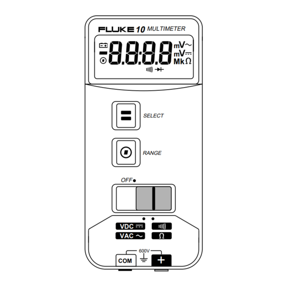
10 Users Manual Digital Reading Replace Battery Measurement Manual Range Units Continuity Diode Test Beeper Enabled Note: Before using, peel off plastic lens protector, starting at any corner. acz01f.eps Figure 1. Display Standby Mode In Standby mode, the display goes blank to preserve battery life. The meter beeps and enters Standby if it is LEFT ON BUT IS INACTIVE for more than 45 minutes. -
Page 7: Operating Features
Operating Features Operating Features Toggle Between Volts DC and AC, or Continuity and Ohms SELECT Ranging RANGE Operations 3-Position Slide-Switch Continuity/Diode Volts DC/AC Test, and Ohms Position 600V Input Jack Common (Return) Jack acz02f.eps Figure 2. Operating Features... -
Page 8: Using Accessories
10 Users Manual Using Accessories When using accessories, put the slide-switch in the volts position. For ease of reading, manually select the 4000 mV range. In the 4000 mV range, 1 mV corresponds to 1 unit being measured by the accessory. -
Page 9: Using The Autorange And Manual Range Modes
Using the Autorange and Manual Range Modes Using the Autorange and Manual Range Modes The range for each function determines the highest value the meter can measure. If the range is too low, the meter displays OL (overload) and beeps. If the range is too high, the display shows fewer digits of resolution. -
Page 10: Measuring Voltage
10 Users Manual Measuring Voltage Insert the test leads in the jacks. To select a voltage function, put the slide-switch in the middle position. (Figure 3.) ] SELECT button to toggle between dc and ac. Press the [ Touch the probes to the test points, and read the display. - Page 11 Measuring Voltage Volts DC Volts AC MULTIMETER MULTIMETER SELECT SELECT RANGE RANGE 600V 600V acz03f.eps Figure 3. Measuring Voltage...
-
Page 12: Testing Continuity And Measuring Resistance
10 Users Manual Testing Continuity And Measuring Resistance Insert the test leads in the jacks, and turn off power to the circuit under test. External voltage across the components causes invalid readings. Put the slide-switch in the continuity / ohms position (Figure 4). The meter selects the continuity/diode or ohms function. - Page 13 Turning the Beeper Off Resistance Continuity Test MULTIMETER MULTIMETER MULTIMETER SELECT SELECT SELECT RANGE RANGE RANGE 600V 600V 600V Short Open acz04f.eps Figure 4. Continuity Test and Resistance Measurement...
-
Page 14: Testing Diodes
10 Users Manual Testing Diodes Insert the test leads in the jacks. Put the slide-switch in the continuity / ohms position. The meter selects either the continuity / diode ( R G ) or ohms (e) function. If ohms is selected, press [ ] SELECT to toggle to the continuity/diode function. - Page 15 Testing Diodes MULTIMETER MULTIMETER MULTIMETER SELECT SELECT SELECT RANGE RANGE RANGE 600V 600V 600V acz05f.eps Figure 5. Testing Diodes...
-
Page 16: Maintenance
10 Users Manual Maintenance W Warning To avoid electrical shock or damage to the meter, do not get water inside the case, and remove the test leads and any input signals before opening the case. Wipe the case with a damp cloth and detergent. -
Page 17: Specifications
Specifications Specifications This meter complies with Part 15 of FCC Rules. Operation is subject to the following conditions: This meter may not cause harmful interference. This meter must accept any interference received, including interference that may cause undesired operation. Accuracy is specified for a period of one year after calibration, at 18 °C to 28 °C (64 °F to 82 °F) with relative humidity to 90 %. - Page 18 −30 °C to 60 °C indefinitely (to −40 °C for 100 hrs) Storage Temperature 0.1 x (specified accuracy) / °C (<18 °C or >28 °C) Temperature Coefficient 0 % to 90 % (−10 °C to 35 °C); Relative Humidity 0 % to 70 % (35 °C to 50 °C) Battery Type...
- Page 19 Specifications Function Range Resolution Accuracy (50 to 400 Hz) 4000 mV 1 mV +/- (2.9 % + 3) 4.000 V 0.001 V +/- (2.9 % + 3) 40.00 V 0.01 V +/- (2.9 % + 3) 400.0 V 0.1 V +/- (2.9 % + 3) 600 V +/- (2.9 % + 3)
- Page 20 Normal Mode Function Protection * (Nominal) (1 kQ Unbalance) Rejection 600 V dc >10 MQ <100 pF 100 dB @ dc @ >50 dB @ 50 Hz or 60 Hz 50 or 60 Hz 50 or 60 Hz 600 V rms >5 MQ <100 pF...
- Page 21 Mouser Electronics Authorized Distributor Click to View Pricing, Inventory, Delivery & Lifecycle Information: Fluke FLUKE-10...