Table of Contents

Related Manuals for Bosch PCH6A5B90A


Summary of Contents for Bosch PCH6A5B90A
- Page 1 PCH6A5B90A, PCI6A5B90A, PCR7A5B90A, PCS7A5B90A, PCT9A5B90A, PCR9A5B90A This cooktop is approved for use with Natural Gas and Universal LPG. Leave these instructions with the owner. USER INSTRUCTIONS INSTALLATION INSTRUCTIONS MAINTENANCE INSTRUCTIONS...
-
Page 2: Table Of Contents
Warranty conditions ......18 Produktinfo Additional information on products, accessories, replacement parts and services can be found at www.bosch-home.com and in the online shop www.bosch-eshop.com... -
Page 3: Intended Use
Intended use a person responsible for their safety. Children 8Intended use should be supervised to ensure that they do not play with the appliance. Read these instructions carefully. You will only All operations relating to installation, I n t e n d e d u s e be able to use your appliance safely and connection, regulation and conversion to effectively when you have read them. -
Page 4: Important Safety Information
Important safety information Do not store or use corrosive chemicals, Risk of fire! (Important safety ■ products which produce fumes, information inflammable materials or non-food products below or near this domestic appliance. Fat or oil which is overheated can catch fire DO NOT MODIFY THIS APPLIANCE. -
Page 5: Installation And Connection
Installation and connection Preparing to install 5Installation and connection Refer to AS/NZS 5601.1 for piping size details. These built-in cooktops are intended to be inserted in a Statutory requirements benchtop cutout. c o n n e c t i o n I n s t a l l a t i o n a n d This installation must conform with the following: Do not stick the cooktop onto the worktop with silicone. -
Page 6: Clearances
Installation and connection If the base of the hotplate can be touched, a protecting shield must be fitted. The shield must be at least 10 mm from the lowest ■ part of the hotplate and must be capable of withstanding the appliance temperatures. Minimum thickness of benchtop is 30 mm. -
Page 7: Electrical Connection
Installation and connection Depending on the model, the adhesive seal may be Electrical connection factory-fitted. If this is the case, it should not be An electrical 10 amp socket needs to be within 1 m of removed under any circumstances, since the adhesive the hotplate to allow electrical connection. -
Page 8: Gas Connection
Installation and connection Gas connection There are two ways to carry out the connection to the main gas line: During the planning stage, consider the position of supply connections. The hotplate can be connected with rigid pipe as ■ specified in AS/NZS 5601.1 The cooktop must be connected to the gas supply with Flexible Hose: If installing with a hose assembly, it upstream connection of an isolation valve in... - Page 9 Installation and connection Replacing the injectors Request change-over injectors from our customer service deparment (refer injector chart below for sizes). Natural Gas Universal LPG Hourly Gas Injector Hourly Gas Injector Consumption mark Consumption mark (MJ) (MJ) Economy burner Standard- output 6.85 Adjusting the gas valves burner...
-
Page 10: Getting To Know Your Appliance
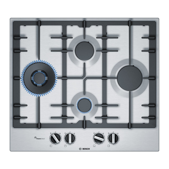
Getting to know your appliance *Getting to know your appliance Burner locations y o u r a p p l i a n c e G e t t i n g t o k n o w Pan supports Control knobs "... -
Page 11: Controls And Burners
Getting to know your appliance Controls and burners It is essential to ensure that all the burner parts and pan supports are correctly installed for the appliance to Each control knob is marked with the burner it controls. work correctly. Do not swap the burner caps around. You can use the control knobs to set the output Always remove the pan supports carefully. -
Page 12: Gas Burners
Gas burners Warning – Risk of deflagration! Simmer plate If the burner does not switch on after 15 seconds, This accessory part is only suita- switch off the control knob and open the door or ble for simmering. It can be window in the room. -
Page 13: Instructions For Use
Settings table and tips Instructions for use Do not use large pots or heavy weights which can When using certain pots or pans, a slight and Note: bend the pan support or temporary deformation of the steel cooking surface may deflect flame onto the occur. - Page 14 Settings table and tips This example shows the preparation of fish soup using Food Total Step 1 Step 2 the high-output burner, the standard-output burner and time in Burner ˜ § v ˜ § v the wok burner. min. When using the high-output burner (recommended Vegetables and pulses option), the total cooking time is between 12 and 17 Boiled potatoes (mashed, potato salad)
- Page 15 Settings table and tips Food Total Step 1 Step 2 Food Total Step 1 Step 2 time in time in Burner Burner ˜ § v ˜ § v ˜ § v ˜ § v min. min. Spanish tortilla High-output 9-11 9-11 š...
-
Page 16: Cleaning And Maintenance
Cleaning and maintenance For pan-cooked dishes, heat the oil up first. As soon Food Total Step 1 Step 2 ■ as you have started the frying, keep the pan at a time in Burner ˜ § v ˜ § v constant temperature by adjusting the heating min. -
Page 17: Trouble Shooting
Trouble shooting Do not leave acidic liquids (e.g. lemon juice, vinegar, Caution! etc.) on the hob. The stainless steel cleaner must not be used in the area around the controls. The (printed) symbols may be wiped off. 3Trouble shooting DO NOT MODIFY THIS APPLIANCE. T r o u b l e s h o o t i n g Only authorized personnel from the Service Centre are qualified to work on the appliance. -
Page 18: Customer Service
Customer service 4Customer service When contacting our Technical Assistance Service, C u s t o m e r s e r v i c e please provide the product number (E-Nr.) and production number (FD) of the appliance. This information is given on the specifications plate located on the lower section of the hob and on the label in the user manual. - Page 20 *9001124119* 9001124119 970327(A)