Acer ICONIA TAB Service Manual
Hide thumbs
Also See for ICONIA TAB:
- Service manual (115 pages) ,
- User manual (73 pages) ,
- Quick manual (32 pages)
Table of Contents
Advertisement
Quick Links
Advertisement
Table of Contents

Related Manuals for Acer ICONIA TAB


Summary of Contents for Acer ICONIA TAB
- Page 1 ICONIA TAB S E R V I C E G U I D E G U I D E...
-
Page 2: Table Of Contents
Table of Contents Chapter 1. Hardware Specifications and Configurations Features ............1-2 Tablet tour. - Page 3 ICONIA TAB ........
-
Page 4: Revision History
Updates Copyright Copyright © 2013 by Acer Incorporated. All rights reserved. No part of this publication may be reproduced, transmitted, transcribed, stored in a retrieval system, or translated into any language or computer language, in any form or by any means, electronic, mechanical, magnetic, optical, chemical, manual or otherwise, without the prior written permission of Acer Incorporated. - Page 5 Conventions The following conventions are used in this manual: WARNING: Indicates a potential for personal injury. CAUTION: Indicates a potential loss of data or damage to equipment. IMPORTANT: Indicates information that is important to know for the proper completion of a procedure, choice of an option, or completing a task.
- Page 6 For Acer-authorized service providers: Your Acer office may have a different part number code than those given in the FRU list of this printed service guide. The list provided by your regional Acer office must be used to order FRU...
- Page 7 CHAPTER Hardware Specifications and Configurations Hardware Specifications and Configurations ....1-2 Features ............1-2 Tablet tour .
-
Page 8: Chapter 1. Hardware Specifications And Configurations
Hardware Specifications and Configurations Features The following is a summary of the computer’s many features: Form Factor • 7” Tablet Operating System • Android Jelly BeaN Platform • MTK 8317T 1.2G Dual Core System Memory • RAM: DDR3 1GB • eMMC: 8GB / 16GB Display •... -
Page 9: Expansion Slot
Connectivity Wi-Fi • IEEE 802.11 b/g/n - NH520 Bluetooth ® • Bluetooth • Micro USB 2.0 Type B port • Support USB 2.0 Client • NH520 module Expansion Slot • MicroSD memory card up to 32G (SDHC 2.0 compatible) Special Keys and Controls •... -
Page 10: Power Adapter And Battery
Power Adapter and Battery Battery • Rechargeable Lithium-Ion battery • Capacity 10W Power Adapter • Voltage range/frequency: 100 ~ 240V AC, 50/60 Hz • DC output: 5.35V and 2A, 10.7W Others • Reset hole Green Requirement • Rohs compliance • WEEE compliance •... -
Page 11: Tablet Tour
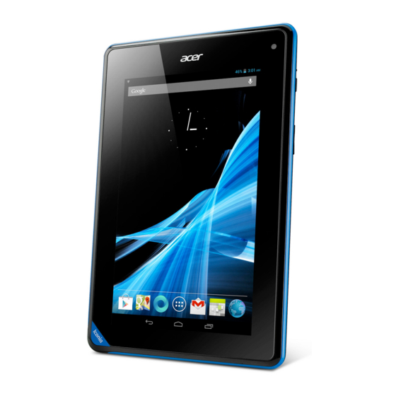
Tablet tour Front View Figure 1-1. Front View Table 1-1. Front View Item Description Touch Screen 7-inch, 1024 x 600 capacitive touch screen. A 0.3-megapixel camera for video chatting and self-portrait Camera images. Microphone Receives audio input. Hardware Specifications and Configurations... -
Page 12: Rear View
Rear View Figure 1-2. Rear View Table 1-2. Rear View Item Description Speakers Emits stereo audio. Hardware Specifications and Configurations... -
Page 13: Top View
Top View Figure 1-3. Top View Table 1-3. Top View Item Description Headset Jack Connects to stereo headphones. Bottom View Figure 1-4. Bottom View Table 1-4. Bottom View Item Description Connects to a computer or power adapter with a USB Micro-B USB Port cable. -
Page 14: Right View
Right View Figure 1-5. Right View Table 1-5. Right View Item Description Insert a pointed object, such as a paper clip, into the reset Reset Hole hole to reset the tablet to its factory defaults. • Press and hold to turn the tablet on or off. Power Button •... -
Page 15: System Block Diagram
System Block Diagram Figure 1-6. System Block Diagram Hardware Specifications and Configurations... -
Page 16: Specifications Table
Specifications Table Computer specifications Item Metric Imperial Dimensions Length 197.4 mm 7.77 in Width 128.5 mm 5.06 in Height (front to rear) 12.4 mm 0.49 in Weight 345 g 0.76 lb Input power Operating voltage AC Input: 100V ~ 240V / DC Output: 5.35V Operating current AC Input: 0.3A / DC Output: 2.0A Temperature... - Page 17 System Board Major Chips Item Specification MT8317T 1.2GHz dual-core Cortex-A9 AP MCU 520 MHz ARM1176 + 260 MHz DSP modem cores MD MCU Graphics Processor 3D graphics (OpenGLIES 2.0) LVDS transmitter SN75LVDS83BZQLR MT6329 DDR3L DDR3 1G ULPI Phy for USB Bluetooth Azurewave AW-NH520 Wireless...
- Page 18 Processor Item Specification MT8317T 1.2GHz dual-core Cortex-A9 AP MCU 520 MHz ARM1176 + 260 MHz DSP modem cores MD MCU CPU package TFBGA 12.2mm*12.2mm, 537-ball, 0.4mm pitch package. Processor Specifications Bus Speed Cache Core Item Cores Mfg Tech Package Speed (FSB/DMI/QBI) Size Voltage...
- Page 19 LAN Interface Item Specification LAN Chipset No support on board LAN LAN connector type LAN connector location Bluetooth Interface Item Specification Chipset AW-NH520 Bluetooth 2.1+Enhanced Data Rate (EDR) / Data throughput BT3.0+HX/BT4.0 Protocol Interface UART Connector type I-PEX Supported protocol Bluetooth Module Item Specification...
- Page 20 LED 7.0” Item Specification Vendor/model name INNOLUX Screen Diagonal (mm) 177.8mm Active Area (mm) 153.6(W) × 90.0(H) mm Display resolution (pixels) 1024 × 3(RGB) × 600 Pixel Pitch (mm) 0.05(W) × 0.15(H) mm Typical White Luminance (cd/m also called Brightness Contrast Ratio Response Time (Optical Rise 10/25...
- Page 21 Rear Camera Item Specification Vendor and model Type Mini Card Item Specification Number supported Features 3G Card Item Specification Features Audio Codec Amplifier Item Specification Audio Controller MT6329 Audio onboard or optional On board Mono or Stereo Stereo Resolution 24-bit data resolution Compatibility I2S Interface;...
- Page 22 Audio Codec Amplifier Item Specification MT6329 dual-channel, 0.7W into 8Ω, high efficiency Class Amplifier IC AB/D audio amplifiers MT6329 has built-in dual channel high efficiency class AB/D audio power amplifier capable of delivering 0.7 watt of power to an 8 ohm (each channel, stereo) BTL load and up to 1.7 watts onto parallel equivalent 4-ohm load (mono in two channels) from a 3.7V battery supply.
- Page 23 Video Interface Item Specification Chipset N/A (Graphic function is embedded in CPU) Package Interface Compatibility Sampling rate VRAM Item Specification Chipset Memory size Interface USB Port Item Specification USB compliance level USB2.0 Modes Device Speed Low, Full and High Number of USB port(s) 1 port for Device Location JP23...
- Page 24 AC Adapter Item Specification Input rating 100Vac to 240 Vac Maximum input AC current 0.5A(RMS) Max. @100Vac & maximum load The inrush current will not cause any components damage Inrush current including input fuse and bridge diode. Meet EPS 2.0 Level V The PSU Average efficiency is greater than 73.9%, Efficiency measurement @ 25%, 50%, 75% and 100% load with input...
- Page 25 CHAPTER Diagnostic Utilities Diagnostic Utilities ........2-2 Introduction .
-
Page 26: Chapter 2. Diagnostic Utilities
Diagnostic Utilities Introduction The ICONIA TAB has a software tool designed to diagnose problems with its hardware components. Diagnostic Tool SOP On the device, go to the applications screen and look for the diagnostic tool named ACTP. Figure 2-1. Device Applications Screen Tap the ACTP icon to start the testing process. -
Page 27: Main Menu
Main Menu The diagnostic tool tests the functions of TouchSlope, Double Touch, RGB, HW Keys, Front Camera, Speaker, Top Mic, SD Card and G-sensor. Select the function(s) you want to test, and then tap OK to start. Step 1 – Select item(s) Step 2 –... - Page 28 2. Double Touch Test The Double Touch Test is used to test 2 points touch on the panel. Use two (2) fingers to draw from the left to the right along the blue bars. When the top bars has been drawn successfully, continue to draw on the blue bars on the right, then on the bottom and on the left.
- Page 29 4. Hardware Keys Test Press the volume up and volume down keys. The Vol - and Vol + text on the screen will change if the HW keys work and auto pass the test. Or, judge the test by tapping the “Failure” button or touch “Retest” to retest. Figure 2-6.
- Page 30 6. Speaker Music plays for 5 seconds. When the music stops playing, tap “Pass” if the test passes, “Failure” if the test fails, or “Retest” to redo the test. Figure 2-8. Speaker Test 7. Top Microphone Test Tap the screen to start the test. When “Recording” appears, speak into the device. Check the recorded sound quality when the screen shows “Replaying”.
- Page 31 8. SD Card Insert an SD card into the device. The test starts automatically. If the SD card read-write capability is successful, a message appears on the screen and the test automatically closes. Otherwise, “Failure” appears on the screen. Tap “Failure” if the test fails or “Retest” to redo the test.
- Page 32 CHAPTER Jumper and Connectors Location Jumper and Connector Locations ......3-2 Mainboard Top View ..........3-2 Mainboard Bottom View .
-
Page 33: Chapter 3. Jumper And Connector Locations
Jumper and Connector Locations Mainboard Top View JP18 JP27 JP23 Figure 3-1. Mainboard Top Table 3-1. Mainboard Top Jumper and Connectors Item Description Item Description Reset Button JP18 Camera Power Button JP27 Headphone Jack Volume Up JP23 Micro USB Volume Down Jumper and Connector Locations... -
Page 34: Mainboard Bottom View
Mainboard Bottom View JP20 JP29 JP30 JP22 JP19 JP26 Figure 3-2. Mainboard Bottom Table 3-2. Mainboard Bottom Jumper and Connectors Item Description Item Description JP19 Microphone JP30 Battery Connector LCD Connector JP22 SD Card JP26 Touch Connector JP20 Speaker Connector WiFi Antenna JP29 Vibrator... - Page 35 CHAPTER Troubleshooting Troubleshooting .........4-2 General Information .
-
Page 36: General Information
NOTE: The diagnostic tests are intended to test only Acer products. Non-Acer products, prototype cards, or modified options can give false errors and invalid system responses. Obtain as much detail as possible about the problem. -
Page 37: Power On Issues
Power On Issues If the system does not power on, perform the following: Start Swap the BATT Check BATT Swap M/B Figure 4-1. Power On Issues Troubleshooting... -
Page 38: No Display Issues
No Display Issues If the system does not display, perform the following: Start Go to power on power on Trouble shooting step Check LCD cable Re-assembly LCD cable assembly ok? Check LCD panel Swap LCD panel Swap M/B Figure 4-2. No Display Issues Troubleshooting... -
Page 39: Lcd Picture Failure
LCD Picture Failure If the LCD picture fails, perform the following: Start Re-assembly Check LCD cable LCD cable assembly ok? Swap LCD panel Check LCD panel Swap M/B Figure 4-3. LCD Picture Failure Troubleshooting... -
Page 40: Touch Screen Failure
Touch Screen Failure If the touch screen fails, perform the following: Start Check touch Re-assembly touch screen cable assembly screen cable Check touch Swap touch screen panel screen panel Swap M/B Figure 4-4. Touch Screen Failure Troubleshooting... -
Page 41: Internal Speaker Failure
Internal Speaker Failure If the internal speakers fail, perform the following: Start Swap SPK Check SPK Swap M/B Figure 4-5. Internal Speaker Failure Troubleshooting... -
Page 42: Internal Microphone Failure
Internal Microphone Failure If the internal microphone fails, perform the following: Start Swap Check the Up MIC the Up MIC Swap M/B Figure 4-6. Internal Up Microphone Failure Troubleshooting... -
Page 43: Extend Earphone Failure
Extend Earphone Failure If the external earphone fails, perform the following: Start Swap earphone Check earphone fixture fixture Swap M/B Figure 4-7. Extend Earphone Failure Troubleshooting... -
Page 44: Usb Test Failure
USB Test Failure If the UBS test fails, perform the following: Start Check USB fixture Swap USB fixture Swap M/B Figure 4-8. USB Test Failure 4-10 Troubleshooting... -
Page 45: Front Camera Failure
Front Camera Failure If the front camera fails, perform the following: Start Swap the Check the camera/B Camera/B Swap M/B Figure 4-9. Front Camera Failure Troubleshooting 4-11... -
Page 46: Wifi & Bt Function Test Failure
WiFi & BT Function Test Failure If the WiFi and Bluetooth function tests fail, perform the following: Start Check the Swap the WiFi & BT antenna antenna Swap M/B Figure 4-10. WiFi & BT Function Test Failure 4-12 Troubleshooting... -
Page 47: Gps Function Test Failure
GPS Function Test Failure If the GPS function fails, perform the following: Start Check the Swap the GPS antenna antenna Swap M/B Figure 4-11. GPS Function Test Failure Troubleshooting 4-13... -
Page 48: Other Functions Failure
Other Functions Failure If other functions, such as G-Sensor, SD, hardware keys, micro-USB, and reset test fail, perform the following: Check the component connection to the mainboard. To test for mainboard fault, swap the mainboard. 4-14 Troubleshooting... - Page 49 CHAPTER Service and Maintenance Service and Maintenance ........5-2 Introduction .
-
Page 50: Chapter 5. Service And Maintenance
Service and Maintenance Introduction This chapter contains general information about the tablet, a list of tools needed to perform the required maintenance and step by step procedures on how to remove and install components from the tablet computer. Recommended Equipment The following tools are required to perform maintenance on the tablet: •... -
Page 51: Maintenance Flowchart
Maintenance Flowchart The flowchart in Figure 5-1 provides a graphic representation of the module removal and installation sequences. It provides information on what components need to be removed and installed during servicing Micro SD Card Lower Case WiFi/Bluetooth Speaker Microphone Mainboard GPS Antenna Antenna... -
Page 52: Getting Started
Getting Started The flowchart (Figure 5-1, page 5-3) identifies sections illustrating the entire removal and installation sequence. Observe the order of the sequence to avoid damage to any of the hardware components. Perform the following prior to performing any maintenance procedures: Place the system on a flat work surface. -
Page 53: Micro Sd Card Removal
Micro SD Card Removal Open the micro SD card cover. Figure 5-3. Opening the Micro SD Card Cover Push the micro SD card to eject it from the slot, and then remove the card. Figure 5-4. Removing the Micro SD Card Service and Maintenance... - Page 54 Secure the micro SD card cover. Figure 5-5. Securing the Micro SD Card Cover Service and Maintenance...
-
Page 55: Micro Sd Card Installation
Micro SD Card Installation Open the micro SD card cover. (Figure 5-3, page 5-5) Push the micro SD card into the slot until it clicks into place. Figure 5-6. Installing the Micro SD Card Close the micro SD card cover. (Figure 5-5, page 5-6) Service and Maintenance... -
Page 56: Lower Case Removal
Lower Case Removal Prerequisite: Micro SD Card Removal on page Using a plastic pry, pry into the lower-left corner of the tablet to slightly create an opening. Figure 5-7. Prying for an Opening Pry to release the bottom side latches, following the direction of the arrow. Figure 5-8. - Page 57 Pry to release the right side latches starting from the lower edge towards the top. Figure 5-9. Unlocking the Right Side Latches Pry to release the left side latches starting from the lower edge towards the top. Figure 5-10. Unlocking the Left Side Latches Service and Maintenance...
- Page 58 Pry to release the top side latches. Figure 5-11. Unlocking the Top Side Latches Pull the lower case from the bezel by the right side. Figure 5-12. Opening the Lower Case CAUTION: Do not abruptly pull the lower case from the bezel, a connector underneath must be disconnected first.
- Page 59 Locate the battery cable connector (A) and speaker cable connector (B). Figure 5-13. Locating the Cable Connectors Remove the protective tape covering the battery cable and the speaker cable. Figure 5-14. Removing the Protective Tape Service and Maintenance 5-11...
- Page 60 Disconnect the battery cable connector from the mainboard connector. Figure 5-15. Disconnecting the Battery Cable Disconnect the speaker cable connector from the mainboard connector. This action completely detaches the lower case from the bezel. Figure 5-16. Disconnecting the Speaker Cable 5-12 Service and Maintenance...
- Page 61 The following components can be found on the bezel: GPS antenna (A) WLAN antenna (B) Camera (C) WLAN antenna connector (D) GPS antenna connector (E) Microphone connector (F) Microphone (G) LCD panel connector (H) Touch panel connector (I) Figure 5-17. Components Overview Service and Maintenance 5-13...
-
Page 62: Lower Case Installation
Lower Case Installation Before installing the lower case, make sure the following are installed: • Speaker (if not, perform Speaker Installation on page 5-20). • Microphone (if not, perform Microphone Installation on page 5-23). • Mainboard (if not, perform Mainboard Installation on page 5-29). - Page 63 Connect the battery cable connector to the mainboard connector. Figure 5-19. Connecting the Battery Cable Attach the protective tape to secure the battery cable and speaker cable. Figure 5-20. Securing the Protective Tape Service and Maintenance 5-15...
- Page 64 Route the speaker cable to hold it in place as the lower case is attached to the bezel. Figure 5-21. Routing the Speaker Cable Align and snap the left side latches to attach the lower case to the bezel. Figure 5-22. Installing the Lower Case (1 of 4) 5-16 Service and Maintenance...
- Page 65 Snap the right side latches. Figure 5-23. Installing the Lower Case (2 of 4) Snap the bottom side latches. Figure 5-24. Installing the Lower Case (3 of 4) Service and Maintenance 5-17...
- Page 66 Snap the top side latches to completely secure the lower case to the bezel. Figure 5-25. Installing the Lower Case (4 of 4) 5-18 Service and Maintenance...
-
Page 67: Speaker Removal
Speaker Removal Prerequisite Lower Case Removal on page Lift to detach the speaker from the lower case. Figure 5-26. Removing the Speaker Service and Maintenance 5-19... -
Page 68: Speaker Installation
Speaker Installation Peel off the sheet covering the speaker adhesive. Install the speaker to its slot on the lower case. Figure 5-27. Installing the Speaker Install the lower case (see Lower Case Installation on page 5-14). 5-20 Service and Maintenance... -
Page 69: Microphone Removal
Microphone Removal Prerequisite Lower Case Removal on page Remove the protective tape covering the microphone cable. Figure 5-28. Removing the Protective Tape Disconnect the microphone cable connector from the mainboard connector. Figure 5-29. Disconnecting the Microphone Cable Service and Maintenance 5-21... - Page 70 Lift to remove the microphone from its slot. Figure 5-30. Removing the Microphone 5-22 Service and Maintenance...
-
Page 71: Microphone Installation
Microphone Installation Install the microphone to its slot on the bezel. Figure 5-31. Installing the Microphone Connect the microphone cable connector to the mainboard connector. Figure 5-32. Connecting the Microphone Cable Service and Maintenance 5-23... - Page 72 Attach the protective tape to hold the microphone cable on the LCD panel cable. Figure 5-33. Attaching the Protective Tape Install the lower case (see Lower Case Installation on page 5-14). 5-24 Service and Maintenance...
-
Page 73: Mainboard Removal
Mainboard Removal Prerequisite: Lower Case Removal on page Remove the protective tape covering the microphone cable. Figure 5-34. Removing the Protective Tape Disconnect the following connectors from the mainboard connectors: • WLAN antenna connector (A) • GPS antenna connector (B) •... - Page 74 Remove the rubber. Figure 5-36. Removing the Rubber Pull out the connector pin to release the lock and then remove the touch panel FPC. Figure 5-37. Disconnecting the Touch Panel FPC 5-26 Service and Maintenance...
- Page 75 Disconnect the LCD FPC cable. Figure 5-38. Disconnecting the LCD FPC Cable Remove the five (5) screws securing the mainboard to the bezel. Figure 5-39. Removing the Mainboard Screws Service and Maintenance 5-27...
- Page 76 Lift to remove the mainboard from the bezel. Figure 5-40. Removing the Mainboard 5-28 Service and Maintenance...
-
Page 77: Mainboard Installation
Mainboard Installation Align the mainboard and connect the camera connector to the mainboard connector. TIP: Make sure that no cable is placed under the mainboard. Figure 5-41. Connecting the Camera Connector Attach the five (5) screws to secure the mainboard to the bezel. NOTE: Screw torque = 1.0~1.5 kgf.cm Figure 5-42. - Page 78 Connect the LCD FPC cable into the mainboard connector and then push the pin to lock. Figure 5-43. Connecting the LCD FPC Cable With the connector pin outwards, connect the touch panel FPC cable to the mainboard connector and then push the pin to lock. Figure 5-44.
- Page 79 Attach the rubber to protect the touch panel FPC. Figure 5-45. Securing the Rubber Connect the following cable connectors: • WLAN antenna connector (A) • GPS antenna connector (B) • Microphone cable connector (C) Figure 5-46. Connecting the Cables to the Mainboard Service and Maintenance 5-31...
- Page 80 Attach the protective tape. Figure 5-47. Connecting the Cables to the Mainboard Install the lower case (see Lower Case Installation on page 5-14). Table 5-2. Mainboard Screws Screw Name Screw Type Screw Torque Quantity M 1.6 x 3.0 1.0 ~ 1.5 kgf.cm 5-32 Service and Maintenance...
-
Page 81: Wlan Antenna Removal
WLAN Antenna Removal Prerequisite: Lower Case Removal on page Remove the protective tape securing the WLAN antenna cable in place. Figure 5-48. Removing the Protective Tape Disconnect the WLAN antenna connector from the mainboard connector and remove the cable from the guides on the bezel. - Page 82 Using the tweezers, detach the WLAN antenna from the bezel. Figure 5-50. Removing the WLAN Antenna 5-34 Service and Maintenance...
-
Page 83: Wlan Antenna Installation
WLAN Antenna Installation Using the tweezers, align and install the WLAN antenna to the antenna slot on the bezel. Figure 5-51. Installing the WLAN Antenna (1 of 2) Route the WLAN antenna cable through the guides on the bezel and connect the WLAN antenna connector to the mainboard connector. - Page 84 Attach the mylar. Figure 5-53. Securing the Mylar Install the lower case (see Lower Case Installation on page 5-14). 5-36 Service and Maintenance...
-
Page 85: Gps Antenna Removal
GPS Antenna Removal Prerequisite: Lower Case Removal on page Detach the protective tape securing the GPS antenna cable to the bezel. Figure 5-54. Removing the Protective Tape Remove the mylar. Figure 5-55. Removing the Mylar Service and Maintenance 5-37... - Page 86 Disconnect the GPS antenna connector from the mainboard connector. Figure 5-56. Disconnecting the GPS Antenna Connector Using the tweezers, detach the GPS antenna from the bezel. Figure 5-57. Removing the GPS Antenna 5-38 Service and Maintenance...
-
Page 87: Gps Antenna Installation
GPS Antenna Installation Using the tweezers, align and install the GPS antenna to the antenna slot on the bezel. Figure 5-58. Installing the GPS Antenna Connect the GPS antenna connector to the mainboard connector. Figure 5-59. Connecting the GPS Antenna Connector Service and Maintenance 5-39... - Page 88 Attach the mylar to secure the cable in place. Figure 5-60. Attaching the Mylar Attach the protective tape to secure the cable in place. Figure 5-61. Securing the Cable Install the lower case (see Mainboard Installation on page 5-29). 5-40 Service and Maintenance...
-
Page 89: Camera Module Removal
Camera Module Removal Prerequisite: Mainboard Removal on page 5-25 Lift to detach the camera module from the bezel. Figure 5-62. Removing the Camera Service and Maintenance 5-41... -
Page 90: Camera Module Installation
Camera Module Installation Align the camera module to the camera slot on the bezel. Figure 5-63. Aligning the Camera Module Attach the mylar to the camera. Figure 5-64. Attaching the Mylar Install the mainboard (see Mainboard Installation on page 5-29). 5-42 Service and Maintenance... -
Page 91: Battery Removal
Battery Removal Prerequisite: Speaker Removal on page 5-19 Microphone Removal on page 5-21 Mainboard Removal on page 5-25 WLAN Antenna Removal on page 5-33 GPS Antenna Removal on page 5-37 Pry on the upper corner to create an opening. Figure 5-65. - Page 92 Hold the lower case with one hand and abruptly pull the battery with the other hand to detach the adhesives underneath. Figure 5-67. Removing the LG Battery (2 of 2) NOTE: The LG battery on the above figure must be pulled abruptly to avoid misshaping the battery.
-
Page 93: Battery Installation
Battery Installation Align the battery to the lower case, and press slightly to secure the adhesives. Figure 5-69. Installing the LG Battery Figure 5-70. Installing the Sanyo Battery Install the GPS antenna (see GPS Antenna Installation on page 5-39). Install the WLAN antenna (see WLAN Antenna Installation on page 5-35). - Page 94 Install the microphone (see Microphone Installation on page 5-23). Install the speaker (see Speaker Installation on page 5-20). 5-46 Service and Maintenance...
- Page 95 CHAPTER Field Replaceable Unit List FRU (Field Replaceable Unit) List ......6-2 Exploded Diagram ..........6-3 FRU List .
-
Page 96: Chapter 6. Fru (Field Replaceable Unit) List
FRU (Field Replaceable Unit) List This chapter provides the FRU (Field Replaceable Unit) listing in global configurations for the ICONIA TAB. Refer to this chapter whenever ordering for parts to repair or for RMA (Return Merchandise Authorization). NOTE: When ordering FRU parts, check the most up-to-date information available on the regional web or channel. -
Page 97: Exploded Diagram
Exploded Diagram Figure 6-1. Main Assembly Exploded Diagram FRU (Field Replaceable Unit) List... - Page 98 BATTERY ADHESIVE 47.L15N2.003 PANEL MYLAR 47.L1NN2.003 WATER INDICATOR LABEL 47.L1NN2.002 Battery SANYO BAT-715 Prismatic 1S1P SANYO 1 cell KT.00103.001 2640mAh Main COMPAL Mainboard B1-710 Acer Logo LF 8GB eMMC NB.L1N11.001 MB RUBBER 47.L15N2.007 CMOS SPONGE 47.L15N2.005 MIC SET 23.L15N2.001 CAMERA 0.3M 57.L1NN2.001...
-
Page 99: Fru List
LCD COVER IMR WHITE - B1-710 60.L1NN2.001 LCD ASSEMBLY ASSY LCD TOUCH MODULE 7.0" 6M.L1NN2.001 DIGITAL LIGHT DEVICE CAMERA 0.3M 57.L1NN2.001 MAINBOARD Mainboard B1-710 Acer Logo LF 8GB eMMC NB.L1N11.001 Mainboard B1-710 Acer Logo LF 16GB eMMC NB.L1V11.001 FRU (Field Replaceable Unit) List... - Page 100 CATEGORY DESCRIPTION PART NO. MICROPHONE MIC SET 23.L15N2.001 SPEAKER SPEAKER 23.L15N2.002 MISCELLANEOUS CMOS GASKET 47.L15N2.002 BATTERY ADHESIVE 47.L15N2.003 GPS GASKET 47.L15N2.004 CMOS SPONGE 47.L15N2.005 MB RUBBER 47.L15N2.007 SEAL LABEL 47.L1NN2.001 WATER INDICATOR LABEL 47.L1NN2.002 PANEL MYLAR 47.L1NN2.003 ADAPTER Adapter PHIHONG 10W 5V/2A PSAI10R-050Q(A)- KP.0100P.001 R LF Adapter PHIHONG 10W 5V/2A PSAI10R-...
-
Page 101: Screw List
Screw List CATEGORY Description Part No. SCREWS SCREW 1.6D 3L K 3.1D ZK NL CR3 86.L15N2.001 FRU (Field Replaceable Unit) List... - Page 102 CHAPTER Test Compatible Components Test Compatible Components ......7-2 Android OS Environment Test ........7-2...
-
Page 103: Chapter 7. Test Compatible Components
Test Compatible Components This computer’s compatibility is tested and verified by Acer’s internal testing department. All of its system functions are tested under Android OS environment. Refer to the following lists for components, adapter cards, and peripherals which have passed these tests. - Page 104 VENDOR TYPE DESCRIPTION PART NO. Hynix DDR3 1G (2pcs for Memory Chip HYNIX DDRIII 1600 KN.0040G.004 1G) (wifi sku) 4Gb H5TQ4G63MFR-PBC LF+HF 256*16 Kingston 16G (wifi sku) EMMC KINGSTON NAND 16GB KN.16G07.001 KE4CN4K6A LF 19nm SKHynix 16G (wifi sku) EMMC HYNIX NAND 16GB KN.16G0G.006 H26M52002EQR LF+HF Kingston...
- Page 105 VENDOR TYPE DESCRIPTION PART NO. Touch IC Goodix 7", 5-point GT927 7", 5-point, mutual-cap, I2C NC. 25511.001 Test Compatible Components...
- Page 106 CHAPTER Online Support Information Online Support Information ....... .8-2 Introduction ........... . 8-2...
-
Page 107: Chapter 8. Online Support Information
This section describes online technical support services available to help users repair their Acer Systems. For distributors, dealers, ASP or TPM, please refer the technical queries to a local Acer branch office. Acer Branch Offices and Regional Business Units may access our website. However some information sources will require a user i.d.