Toshiba TS2000 Instruction Manual
Robot controller
Hide thumbs
Also See for TS2000:
- Instruction manual (78 pages) ,
- Instruction manual (52 pages) ,
- Instruction manual (40 pages)
Table of Contents
Advertisement
INSTRUCTION MANUAL
TS2000/TS2100 ROBOT CONTROLLER
• Make sure that this instruction manual is delivered to the
final user of Toshiba Machine's industrial robot.
• Before operating the industrial robot, read through and
completely understand this manual.
• After reading through this manual, keep it nearby for future
reference.
TOSHIBA MACHINE CO., LTD.
INTERFACE MANUAL
Notice
NUMAZU, JAPAN
STE 71367–9
Advertisement
Table of Contents

Related Manuals for Toshiba TS2000


Summary of Contents for Toshiba TS2000
- Page 1 INTERFACE MANUAL Notice • Make sure that this instruction manual is delivered to the final user of Toshiba Machine's industrial robot. • Before operating the industrial robot, read through and completely understand this manual. • After reading through this manual, keep it nearby for future reference.
- Page 2 全115P INTERFACE MANUAL Copyright 2004 by Toshiba Machine Co., Ltd. All rights reserved. No part of this document may be reproduced in any form without obtaining prior written permission from Toshiba Machine Co., Ltd. The information contained in this manual is subject to change without prior notice to effect improvements.
- Page 3 TS2000/TS2100 robot controller with an external equipment. This manual is intended for the system designers and manufacturing engineers. The TS2000/TS2100 robot controller can work in concert with the external equipment through digital input and output signals that can be programmed by the SCOL language.
- Page 4 INTERFACE MANUAL Cautions on Safety This manual contains the important information on the robot and controller to prevent injury to the operators and persons nearby, to prevent damages to assets and to assure correct use. Make sure that you well understand the following details (indications and symbols) before reading this manual.
- Page 5 INTERFACE MANUAL To perform the work ranging from robot installation to operation with safety, read through and through the Safety CAUTION Manual provided separately before actually starting the work. STE 71367 – 5 –...
- Page 6 Otherwise, the performance will deteriorate, resulting in troubles. Disassembly Prohibited • To replace parts, use the spare parts designated by Toshiba Machine. • Carry out the maintenance and inspection on a regular basis. Mandatory Otherwise, the equipment may go wrong or accidents will be caused.
-
Page 7: Table Of Contents
INTERFACE MANUAL Table of Contents Page Type of External Cable ..................10 Layout and Name of Connectors ..............10 TS2000/TS2100 Power Cable "ACIN CN1" ..........12 Robot Control Cables.................. 12 1.3.1 TS2000/TS2100 Motor Drive Cable "MOTOR CN2"....... 12 1.3.2 TS2000/TS2100 Encoder Cable "CN3" .......... 12 1.3.3... - Page 8 INTERFACE MANUAL Page Connecting External I/O Signal Cable..............26 Connecting External Input Signal Cable............26 Connecting External Output Signal Cable........... 29 Connecting External I/O Signal Cable............32 Digital Input Signal ..................36 System Input Signal ..................39 Jumper of Safety Measure Signal ............... 61 Digital Output Signal ...................
- Page 9 INTERFACE MANUAL Page Connecting High-Speed Input Signal Cable (Option)........... 106 Fabricating High-Speed Input Signal Cable ..........107 Attaching and Detaching High-Speed Input Signal Cable ......107 11. Connecting Digital Output Power Select Cable............ 109 12. Appendixes ......................110 12.1 System Signal Table ................. 110 12.2 Fabricating Cable Using D-SUB Connector ..........
-
Page 10: Type Of External Cable
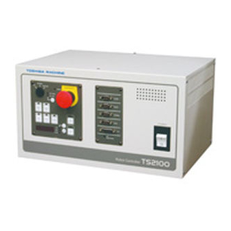
INTERFACE MANUAL Type of External Cable Layout and Name of Connectors The TS2000/TS2100 robot controller is connected with the robot and external equipment, using connectors and terminal block provided on the front and rear sides of the controller. TOSHIBA MACHINE... - Page 11 INTERFACE MANUAL Fig. 1.2 Layout and name of connectors STE 71367 – 11 –...
-
Page 12: Ts2000/Ts2100 Power Cable "Acin Cn1
Fig. 1.1/Fig.1.2–[4] (with cable) The encoder cable is an interface which inputs the rotation angle detection encoder signal (axis 1 to axis 4) of each robot axis to the TS2000/TS2100 robot controller. Connector "CN3" is used. For details, see the Installation & Transport Manual provided separately. -
Page 13: Robot Control Signal Cable "Cn4
Fig. 1.1/Fig.1.2–[11] This is the terminal block for selecting the power (P24 V) for the digital output (32 numbers) of the TS2000/TS2100 robot controller. When the external power supply (P24 V) is used, the power is supplied from this terminal block. -
Page 14: External Output Signal Cable "Cn6
External I/O Signal Cable "CN12" Fig. 1.1/Fig.1.2–[8] The external input/output signal cable is an interface which inputs the digital signal from the external equipment to the TS2000/TS2100 robot controller, and outputs the digital signal from the TS2000/TS2100 robot controller to the external equipment. -
Page 15: Serial I/O Signal Cable
Fig. 1.1/Fig.1.2–[12] Of the serial input and output signals of four (4) channels equipped on the TS2000/TS2100 robot controller, the D-SUB 9-pin connector located on the first line of the front connector unit in Fig. 1.1 is COM1. COM1 is exclusively used for the RS232C and allows data communication with an image processing equipment or other FA equipment that can connect an RS232C interface. -
Page 16: Serial I/O Signal "Pod
Fig. 1.1/Fig.1.2–[15] Of the serial input and output signals of four (4) channels equipped on the TS2000/TS2100 robot controller, the D-SUB 9-pin connector located on the fourth line from the top of the front connector unit in Fig. 1.1 is POD. -
Page 17: Connecting Power Cable
INTERFACE MANUAL Connecting Power Cable To connect the power cable, use the attached connector (JL04V–2E18–10PE–B; made by Japan Aviation Electronics Industry). TS2000/TS2100 User side robot controller TS2000 ø 180 ~ 250 V 50/60 Hz TS2100 ø 190 ~ 250 V... -
Page 18: Connecting Robot Control Cable
Connecting Robot Control Cable Connecting Motor Drive Cable To connect the motors, use the attached cables. The attached standard cables do not include the wiring for the optional axis 5. Connector Connector TS2000 Motor (MOTOR CN2) (MOTOR) Robot body robot controller... - Page 19 INTERFACE MANUAL Connector Connector TS2100 Motor (MOTOR CN2) (MOTOR) Robot body robot controller drive cable Axis 1 Axis 2 Axis 3 Axis 4 (Option) Axis 5 Case Fig. 3.2 Connection of motor drive cables For the motor drive cable connection, see the Installation & Transport Manual. STE 71367 –...
-
Page 20: Connecting Encoder Cable
INTERFACE MANUAL Connecting Encoder Cable 3.2.1 Connecting Encoder Cable To connect the encoders to the TS2000/TS2100 digital servo printed board (X8HW,X8HS), use the attached cables. Encoder TS2000/TS2100 robot controller Robot cable 1RQ/SD X8HS(1) ENCA 1RQ/SD* X8HW(1) Axis 1 encoder 2RQ/SD... -
Page 21: Connecting Encoder Cable (Option)
INTERFACE MANUAL 3.2.2 Connecting Encoder Cable (Option) When the axis 5 (option of TS2000/TS2100) is used, use the attached cable to connect the encoder. CN11 Encoder cable TS2000/TS2100 robot controller Robot 5RQ/SD X8HS(3) ENCA 5RQ/SD* Axis 5 encoder Case Fig. 3.3 Connection of encoder cable For the encoder cable connection, see the Installation &... -
Page 22: Connecting Robot Control Signal Cable
Type P [X8HI (output source type) is selected for the I/O printed board). After confirming the type of your controller, connect the robot control signal cable. [Type N] (When X8HN printed board is used) TS2000/TS2100 Robot control signal cable Robot... - Page 23 The robot control signal controls ON/OFF of the brake for securing the motor shaft, and the end effector such as hand operation. The TS2000/TS2100 controller is provided with five (5) hand input signals and four (4) hand output signals to control the end effector.
- Page 24 Additionally, the hand input and output signals can be controlled by the PLC built in the TS2000/TS2100. For details, see the Simple PLC Function Manual. It is also possible to control the double solenoid device by combining two (2) hand output signals.
- Page 25 INTERFACE MANUAL The specifications of the hand output signal are as follows: • Output type FET output • Electric rating Rated voltage DC24 V, rated current 1 A (max.) • Output circuit structure DC relay drive User side DC relay drive User side DC relay P24V...
-
Page 26: Connecting External I/O Signal Cable
INTERFACE MANUAL Connecting External I/O Signal Cable Connecting External Input Signal Cable To connect the external input signal cable, use the attached connector [XM2D–3701 (socket type connector), XM2S–3711 (connector cover)]. The input common comes in the two (2) types; Type N [X8HN (output sink type) is selected for the I/O printed board and the polarity is the same as in the SR7000 robot] and Type P [X8HI (output source type) is selected for the I/O printed board). - Page 27 INTERFACE MANUAL [Type N] (When X8HN printed board is used) TS2000/TS2100 User side robot controller ( ): Signal name of DIN command (X8HN printed board) DI_1 DI_2 DI_3 DI_4 P24V DI_5 DI_6 Digital input signals DI_7 DI_8 DI_9 Source type DI_10 ("+"...
- Page 28 INTERFACE MANUAL [Type P] (When X8HI printed board is used) TS2000/TS2100 User side robot controller ( ): Signal name of DIN command (X8HI printed board) DI_1 DI_2 DI_3 DI_4 DI_5 DI_6 Digital input signals P24G DI_7 DI_8 Sink type DI_9 ("...
-
Page 29: Connecting External Output Signal Cable
For the function, circuit to use etc., of each signal, see Para. 4.4 and 4.5. Additionally, the external input signals can be controlled by the PLC built in the TS2000/TS2100. For details, see the Simple PLC Function Manual. Connecting External Output Signal Cable To connect the external output signal cable, use the attached connector [XM2A–3701 (plug type connector), XM2S–3711 (connector cover)]. - Page 30 INTERFACE MANUAL [Type N] (When X8HN printed board is used) TS2000/TS2100 User side robot controller ( ): Signal name of DOUT command (X8HN printed board) DO_1 DO_2 DO_3 DO_4 DO_5 Digital output signals DO_6 DO_7 DO_8 DO_9 DO_10 (10) P24G...
- Page 31 INTERFACE MANUAL [Type P] (When X8HI printed board is used) TS2000/TS2100 User side robot controller ( ): Signal name of DOUT command (X8HI printed board) DO_1 DO_2 DO_3 P24V DO_4 DO_5 Digital output signals DO_6 DO_7 Source Type DO_8 (" +" common)
-
Page 32: Connecting External I/O Signal Cable
For the function, circuit to use etc., of each signal, see Para. 4.5, 4.7 and 4.8. Additionally, the external output signals can be controlled by the PLC built in the TS2000/TS2100. For details, see the Simple PLC Function Manual. Connecting External I/O Signal Cable To connect the external input/output signal cable, use the connector [XM2A–2501... - Page 33 INTERFACE MANUAL [Type N] (When X8HN printed board is used) CN12 TS2000/TS2100 User side robot controller ( ): Signal name of DIN command (X8HN printed board) DI_25 (25) DI_26 P24V (26) DI_27 (27) Digital DI_28 input (28) DI_29 signals (29)
- Page 34 INTERFACE MANUAL [Type P] (When X8HI printed board is used) CN12 TS2000/TS2100 User side robot controller ( ): Signal name of DIN command (X8HI printed board) DI_25 (25) DI_26 (26) DI_27 (27) Digital DI_28 input (28) signals DI_29 (29) DI_30...
- Page 35 TS2000/TS2100. For details, see the Simple PLC Function Manual. CAUTION The COM1, HOST, TCPRG, POD and CN12 connectors of the TS2000/TS2100 robot controller are attached with a connector cap, respectively. Unless these connectors are used, be sure to attach the connector caps to prevent static electricity and damage.
-
Page 36: Digital Input Signal
(DI_1 ~ DI_38) with change in signal status monitored during the robot operation. Input type Non-voltage contact input or transistor open collector input. Example of circuit (Input circuit TS2000/TS2100 User side structure) TS2000/TS2100 User side P24V P24V ●... - Page 37 INTERFACE MANUAL Specifications of • Non-voltage contact specifications non-voltage Contact rating DC24 V, 10 mA or over contact and Circuit current: Approx. 7 mA transistor Minimum current DC 24 V, 1 mA 100 Ω or less Contact impedance • Transistor specifications Withstand voltage between collector and emitter 30 V or over Current between collector and emitter...
- Page 38 INTERFACE MANUAL To use only system input signal STROBE as digital input signal DI_33, for instance, change the above bits as shown below. 1 1 1 0 0 0 0 0 To use all system input signals as the digital input signals, specify in the following manner.
-
Page 39: System Input Signal
System Input Signal In addition to a total of thirteen (13) signals which control STOP, CYCLE, etc., of the TS2000/TS2100 robot controller from the external equipment, emergency stop contacts 1 and 2 are also available for the system input signal. - Page 40 INTERFACE MANUAL Table 4.1 List of system input signal ON modes Master mode ON mode EXTERNAL Designation TEACHING INTERNAL EXT. SIGNAL EXT. HOST STROBE (Strobe) PRG_RST (Program reset) STEP_RST (Step reset) CYC_RST (Cycle reset) DO_RST (Output signal reset) ALM_RST (Alarm reset) RUN (Start) EX_SVON (External servo ON) STOP (Stop)
- Page 41 INTERFACE MANUAL Function Used to select an execution program for the TS2000/TS2100 robot controller from the external equipment. The program number selected should use any successive "n" numbers (max. eight (8) numbers) of external digital input signal, which are coded.
- Page 42 INTERFACE MANUAL Program file name and register of it to program number, and assignment of bits to external digital input signals: To select an execution file (i.e., program selection), using digital input or extension input signals, assignment of bits to the controller input signals is necessary.
- Page 43 (4) from "PROG1" ~ "PROG4". To register the program file name to the program number, use the EXTRNSEL. SYS file. Copyright (C) 2001 by TOSHIBA MACHINE CO., LTD. All rights reserved. External select file "EXTRNSEL. SYS"...
- Page 44 INTERFACE MANUAL = "PROG04" = "PROG05" = "PROG06" = "PROG07" = "PROG08" = "PROG09" = "PROG0A" = "PROG0B" = "PROG0C" = "PROG0D" = "PROG0E" = "PROG0F" The initial setting is as shown above. Specify a file name you registered beforehand for the underlined of "PROG**". Example: = "AAA"...
- Page 45 INTERFACE MANUAL Designation PRG_RST (Program reset) Input terminal CN5–32 pin Exclusive signal name used in the controller Signal logic Signal judgment Signal terminal Open Short-circuit Function Used to reset a currently stopped program to step 1. The value of each variable is also reset to zero (0). This signal can be used only in the EXT.
- Page 46 INTERFACE MANUAL Designation STEP_RST (Step reset) Input terminal CN5–14 pin Exclusive signal name used in the controller Signal logic Signal judgment Signal terminal Open Short-circuit Function Used to reset a currently stopped program to step 1. The value of each variable used in the program remains unchanged.
- Page 47 INTERFACE MANUAL Designation CYC_RST (Cycle reset) Input terminal CN5–33 pin Exclusive signal name used in the controller Signal logic Signal judgment Signal terminal Open Short-circuit Function Used to reset a currently stopped program to the step labeled "RCYCLE". The value of each variable used in the program remains unchanged.
- Page 48 Short-circuit Function Used to reset digital output signals (DO_1 ~ DO_32) of the TS2000/TS2100 robot controller from the external equipment. (Extension I/O signals DO_101 (133) ~ DO_120 (152) are also reset.) When reset, all signals of DO_1 ~ DO_32 turn off. When DO_15, DO_16, DO_25 ~ DO_32 are set as the system output signals, however, they are turned on.
- Page 49 Signal terminal Open Short-circuit Function Used to cancel an alarm from the external equipment, which occurred while the TS2000/TS2100 robot controller was ready to start. This signal can be used only in the EXT. SIGNAL mode. Signal timing SYS_RDY ALARM...
- Page 50 Signal judgment Signal terminal Open Short-circuit Function Used to start a program registered in the TS2000/TS2100 robot controller from the external equipment to execute an automatic cycle operation. This signal can be used only in the EXT. SIGNAL mode. Signal timing...
- Page 51 INTERFACE MANUAL Cautions After servo ON, automatic operation starts with the start of the RUN signal. It takes about one (1) second from the input of EX_SVON to the time when the robot is actually ready to work. Set ON the RUN signal only after the SV_RDY signal is ON. Even if the RUN signal is input before the SV_RDY signal is ON, it is neglected and the automatic operation will not be started.
- Page 52 INTERFACE MANUAL Designation EX_SVON (External input servo ON) Input terminal CN6–15 pin Exclusive signal name used in the controller Signal logic Signal judgment Signal terminal Open Short-circuit Function Used to turn on the servo driver main power from the external equipment.
- Page 53 Short-circuit Function Used to stop executing a program registered in the TS2000/TS2100 robot controller from the external equipment. When this signal is open, the program stops after the current motion command has been executed. When this signal is open, the robot cannot be operated.
- Page 54 Short-circuit Function Used to stop from the external equipment a program registered in the TS2000/TS2100 robot controller after current one (1) cycle operation has been executed during automatic operation. This signal can be used only in the EXT. SIGNAL mode.
- Page 55 INTERFACE MANUAL Designation LOW_SPD (Low speed command) Input terminal CN5–36 pin Exclusive signal name used in the controller Signal logic Signal judgment Signal terminal Open Short-circuit Function Used to cause the robot operation speed to low speed from the external equipment. The robot operates at a low speed (the low speed command is valid) while this signal is open.
- Page 56 INTERFACE MANUAL Designation BREAK (Deceleration and stop) Input terminal CN5–17 pin Exclusive signal name used in the controller Signal logic Signal judgment Signal terminal Open Short-circuit Function Used to stop the robot motion from the external equipment. The robot slows down and stops at the same time that this signal is open.
- Page 57 INTERFACE MANUAL Designation SVOFF (Servo OFF) Input terminal CN6–34 pin Exclusive signal name used in the controller Signal logic Signal judgment (Servo OFF) (Normal) Signal terminal Open Short-circuit Function Used to turn off the servo driver main power from the external equipment.
- Page 58 INTERFACE MANUAL Designation EMS*B ~ EMS*C (Emergency stop contacts 1 & 2) Input terminal Between CN6–16 and CN6–35 (Emergency stop contact 2) Between CN6–17 and CN6–36 (Emergency stop contact 1) Signal logic Signal judgment (Emergency (Normal) Signal terminal stop) Open Short-circuit Function Used to emergency-stop the robot from the external...
- Page 59 INTERFACE MANUAL Cautions While this signal is open, the servo power cannot be turned on in any mode. EMS*A ~ EMS*B are assumed to have two (2) normal close contacts interconnected, which should be turned on and off at the same time. If there is a delay in contact operation, the non-conformity detecting function of hardware works to effect an emergency stop.
- Page 60 INTERFACE MANUAL Emergency stop signal line The connection diagram of the emergency stop switch is shown below. TS2000/TS2100 User side TP unit EMS1A EMS1B Emergency stop contact 1 EMS1B P24V EMS1C P24G EMS2A Control panel unit EMS2B Emergency stop contact 2...
-
Page 61: Jumper Of Safety Measure Signal
CN6–17, 36 (EMS1B ~ EMS1C) For the connectors provided with the TS2000/TS2100 robot controller, these signals are already jumpered. If these signals are used or changed, perform wiring with the jumper of connector removed. When operating the robot without using system input signals, be sure to connect the attached connectors to the CN5, CN6 connectors on the controller side. -
Page 62: Digital Output Signal
INTERFACE MANUAL Digital Output Signal Designation Digital output signal DO_1 ~ DO_24, DO_25 ~ DO_32 (system output signals) Connector output Signals DO_1 ~ DO_16 are assigned to CN6–1 ~ 8 pins and terminal 20 ~ 27 pins. (See Fig. 4.3 and 4.4.) DO–15 and 16 can be used as SV–RDY and BT_ALM by changing the user parameter. - Page 63 INTERFACE MANUAL Signal timing When performing pulse output by the PULOUT command, the output pulse width should be 200 ms or over. 200 ms DO_1~DO_32 Example of circuit User side User side P24V P24V ● DC relay ● DC relay ●...
- Page 64 INTERFACE MANUAL To use only system output signal ACK as digital output signal DO_25, for instance, change the above bits as shown below. 1 0 0 0 0 0 0 0 To use all system output signals as the digital output signals, specify in the following manner.
-
Page 65: System Output Signal
System Output Signal A total of twelve (12) system output signals are available. Of them, ten (10) signals are used to output the run status of the TS2000/TS2100 robot controller and the remaining two (2) signals are output via relay contact. - Page 66 INTERFACE MANUAL • Output circuit structure When Type N is selected (when X8HN printed board is used) (1) Transistor output (2) Relay contact output User side User side P24V ● External power supply The above figure exemplifies a normal open contact output P24G structure.
- Page 67 INTERFACE MANUAL When Type P is selected (when X8HI printed board is used) Transistor output (2) Relay contact output User side User side P24V ● External power supply The above figure exemplifies a P24G normal open contact output [ Source Type (" +" common) ] structure.
- Page 68 INTERFACE MANUAL Designation ACK (Acknowledge) Output terminal CN6–9 pin Signal name Signal logic Signal judgment Output terminal High Function This is a response signal to the STROBE, PRG_RST, STEP_RST, CYC_RST and DO_RST signals. When one of these signals is input, the ACK signal is sent back to inform that appropriate processing has finished.
- Page 69 High Function This signal turns on when the MODE switch of the TS2000/TS2100 robot controller is set to "TEACH" and the test operation mode is not selected. During the output of this signal, the robot arm can be guided through the teach pendant.
- Page 70 High Function This signal indicates that the servo power of the TS2000/TS2100 robot controller has turned on with the robot ready for starting an operation. This signal can always be used, irrespective of the master mode selected by means of the MODE switch.
- Page 71 INTERFACE MANUAL Cautions Program so that the RUN signal can be turned on only after the SV_RDY signal turns on. To prevent an internal damage, the servo cannot be turned on about 4.5 seconds after it is turned off. To turn the servo on again, wait at least five (5) seconds after the SVST_A ~ SVST_B signal turns off.
- Page 72 Output terminal CN6–10 pin Signal name Signal logic Signal judgment Output terminal High Function This signal turns on while the TS2000/TS2100 robot controller is in the EXT. SIGNAL mode. Signal timing Mode switch EXT mode EXT.SIGNAL EXT.HOST selector switch EXTSIG...
- Page 73 INTERFACE MANUAL Designation SYS_RDY (System ready) Output terminal CN6–29 pin Signal name Signal logic Signal judgment Output terminal High Function This signal turns on when the robot can start after the controller main power is turned on. With this signal, it is possible to confirm that the robot can be operated.
- Page 74 TS2000/TS2100 robot controller. Signal timing SYS_RDY (O) STOP AUTORUN (O) Cautions This signal will not turn on while the TEACH mode is selected by means of the MODE switch of the TS2000/TS2100 robot controller. STE 71367 – 74 –...
- Page 75 INTERFACE MANUAL Designation CYC_END (Cycle end) Output terminal CN6–12 pin Signal name Signal logic Signal judgment Output terminal High Function This signal turns on after the stop of 1-cycle automatic operation only when the CYCLE signal is made valid in the program execution (RUN) mode and an automatic operation is executed.
- Page 76 INTERFACE MANUAL Designation LOW_ST (Low speed mode ON) Output terminal CN6–31 pin Signal name Signal logic Signal judgment Output terminal High Function This signal turns on while the robot is operating in the low speed mode by the input of system input signal LOW_SPD. This signal can always be used, irrespective of the master mode selected by means of the MODE switch.
- Page 77 INTERFACE MANUAL Designation BT_ALM (Battery alarm) Output terminal CN6–27 pin Signal name Signal logic Signal judgment Output terminal High Function This signal turns on if a battery alarm has occurred in the robot or robot controller. The battery alarm detects all encoders of axis 1 to axis 5 and battery level in the main control board (X8HC).
- Page 78 INTERFACE MANUAL Designation ALARM (Alarm) Output terminal CN6–30 pin Signal name Signal logic Signal judgment Output terminal High Function This signal turns on if an error of level 2, 4 or 8 has occurred in the robot or robot controller. This signal is kept ON during error detection and turns off after the error has been cleared.
- Page 79 INTERFACE MANUAL Designation SVST_A ~ SVST_B (Servo ON contact output) Output terminal Between CN6–13 pin and CN6–32 pin (contact output) Signal logic Signal judgment Open Short-circuit Output terminal Function While the servo power is turned on, the output terminals are short-circuited.
- Page 80 INTERFACE MANUAL Designation EMSST_A ~ EMSST_B (Emergency stop contact output) Output terminal Between CN6–14 pin and CN6–33 pin (contact output) Signal logic Signal judgment Open Short-circuit Output terminal Function While the EMERGENCY stop pushbutton switch provided on the control panel or teach pendant is pressed ON or system input signals "Emergency stop contacts 1 &...
-
Page 81: Fabricating External I/O Signal Cable
Fabricating External I/O Signal Cable When fabricating an external I/O signal cable, observe the following matters. Connectors CN5 and CN6 for the TS2000/TS2100 robot controller should be either the connectors attached to the controller or equivalent connectors. For CN12, prepare the following connector. -
Page 82: Attaching And Detaching External I/O Signal Cable
Before attaching or detaching an external I/O signal cable to or from the TS2000/TS2100 robot controller, be sure to turn off the POWER switch equipped on the rear side of the controller, or the main power in the user's control panel. -
Page 83: Example Of Controller Operation, Using External Signals
INTERFACE MANUAL 4.11 Example of Controller Operation, Using External Signals (1) Normal operation sequence POWER SYS_RDY SV_RDY Approx. 1 sec. EX_SVON SVOFF SVST_A ~SVST_B Program selection STROBE CYCLE STOP AUTORUN CYC_END Set ON the RUN signal only after the SV_RDY signal is ON. Include a sufficient delay time before the program select signal starts between the program select signal input and STROBE signal input. - Page 84 INTERFACE MANUAL (2) Example of restarting the stopped robot Restart after stop (to resume the operation) STOP AUTORUN (O) Restart after stop (to start the program from the top) STOP AUTORUN STEP_RST STE 71367 – 84 –...
- Page 85 INTERFACE MANUAL (3) Example of restarting the robot after servo OFF (emergency stop) Restart after servo OFF (emergency stop) EX_SVON SVOFF (Emergency stop) EMSST_A * When emergency stop contacts 1 ~EMSST_B and 2 are valid SVST_A ~SVST_B Program selection STROBE PRG_ STEP_ CYC_...
- Page 86 INTERFACE MANUAL (4) Example of restarting the robot after error correction To resume the automatic operation after an error has occurred (i.e., processing of automatic operation after error correction): EX_SVON Error has been cleared. ALARM ALM_RST SVST_A ~SVST_B SYS_RDY Approx. 1 sec. SV_RDY Program selection STROBE...
-
Page 87: Connecting Serial Signal Cable
Connecting Serial I/O Signal Cables COM1, HOST, TCPRG, POD and COM2 (Option) The TS2000/TS2100 robot controller is provided with four (4) channels of RS232C serial I/O signals COM1, HOST, TCPRG and POD, and with one (1) channel of optional signal COM2. For the connection, see the figure below. -
Page 88: Attaching And Detaching Serial I/O Signal Cables Com1, Host, Tcprg, Pod And Com2 (Option)
TCPRG, POD and COM2 (option) are the same as in Para. 4.10. For details, see Para. 4.10. The COM1, HOST, TCPRG, POD and CN12 connectors of the TS2000/TS2100 robot controller are CAUTION attached with a connector cap, respectively. Unless these connectors are used, be sure to attach the connector caps to prevent static electricity and damage. -
Page 89: Connecting Tp (Teach Pendant) Cable
INTERFACE MANUAL Connecting TP (Teach Pendant) Cable Connecting TP cable Connector ( TP) TP1000 TS2000/TS2100 TP cable teach pendant robot controller X8HJ P24V P24V To TP control power circuit P24G P24G EMS1A EMS1A Emergency EMS1B EMS1B stop contact 1 RXDG... - Page 90 ON, emergency stop and enable input from the teach pedant, and P24V and P24G signals for supplying the power to the teach pendant. Data transmission between the teach pendant and TS2000/TS2100 robot controller is performed in the current loop system.
-
Page 91: Connecting Ext-I/O Cable
Connecting EXT–I/O Cable Connecting EXT–I/O Cable The EXT–I/O cable is used to connect the TR48DIOCN/TR48DIOC module (option) or Toshiba Machine's designated remote I/O module (option) serving as the slave station. To supply the controller internal power to the TR48DIOCN/TR48DIOC module, the EXT–I/O cable is connected with P24V (24 V) and P24G (0 V). - Page 92 7.2. (For the I/O extension, up to two (2) TR48DIOCN/TR48DIOC modules can be connected.) For details on the TR48DIOCN/TR48DIOC module, see the Simple PLC Function Manual. Terminal block TS2000/TS2100 (EXT I/O) User side robot controller TR48DIOCN/TR48DIOC (slave station 0) P24V...
- Page 93 Fig. 7.3 Connection of EXT–I/O cable when external power supply is used The maximum current capacity of the internal 24 V power supply of the TS2000/TS2100 robot controller, CAUTION which can be fed to the external equipment, is 3 A.
-
Page 94: Ext-I/O Communication
TR48DIOCN/TR48DIOC module to the slave station, inputs and outputs can be controlled via the RS485 serial communication. In addition to the TR48DIOCN/TR48DIOC module, a remote I/O module designated by Toshiba Machine, which can serve as the slave station, can be used also. TR48DIOCN/TR48DIOC 1: Slave station number... - Page 95 • User parameter setting procedures To designate the slave station number of the TS2000/TS2100, observe the following steps. Under [U12] of the USER.PAR (user parameter) file, you can find the following parameter setting related to the extension input and output.
- Page 96 INTERFACE MANUAL Ex.1 When adding one (1) Ex.2 When adding two (2) TR48DIOCN/TR48DIOC TR48DIOCN/TR48DIOC The slave station setting is already described above. Specify the slave station of TR48DIOCN/TR48DIOC to be used, according to the station number set in USER. PAR. For the terminator, when only one (1) TR48DIOCN/TR48DIOC module is used, set ON the terminator setting switch equipped on the module.
-
Page 97: Attaching And Detaching Ext-I/O Cable
For the EXT–I/O cable, use the cable attached to the TR48DIOCN/TR48DIOC module, or a cable which meets the specifications. Before attaching or detaching the EXT–I/O cable to or from the TS2000/TS2100 robot controller, be sure to turn off the POWER switch equipped on the rear side of the controller, or the main power in the user's control panel. -
Page 98: Connecting Extension I/O Signal Cable (Option)
I/O modules exclusive to the TS2000/TS2100 robot controller. They are provided with twenty-eight (28) inputs and twenty (20) outputs, respectively. For the TS2000/TS2100 robot controller, up to two (2) stations can be extended. The output specifications (source type or sink type) differ between the TR48DIOCN and TR48DIOC modules. - Page 99 INTERFACE MANUAL INPUT (Station 0/Station 1): TR48DIOCN User side Signal name of DIN command Station 0/Station 1 DI_101 ~ DI_108 DI_101/DI_133 DI_133 DI_140 (101/133) DI_102/DI_134 (102/134) DI_103/DI_135 (103/135) DI_104/DI_136 (104/136) INCOM1 DI_105/DI_137 (105/137) DI_106/DI_138 Note 1: (106/138) DI_107/DI_139 An example connection of DI_101 ~ (107/139) 108 /DI_133 ~ 140 as shown in the DI_108/DI_140...
- Page 100 INTERFACE MANUAL The specifications of the extension input signal are as follows: • Type of input: Non-voltage contact input or transistor open collector input • Example of application circuit and structure of input circuit Sink type ("–" common) Source type ("+" common) TR48DIOCN User side TR48DIOCN...
-
Page 101: Connecting Extension Output Signal Cable
INTERFACE MANUAL 8.1.2 Connecting Extension Output Signal Cable To connect the extension output signal cable, use the connector attached to the TR48DIOCN module [XM2A–2501 (plug type connector), XM2S–2511 (connector cover)]. Connect the outputs of the TR48DIOCN (DO_101 ~ 120 (station 0) and DO_133 ~ 152 (station 1) to connector OUTPUT provided on the module surface. -
Page 102: Tr48Dioc
INTERFACE MANUAL TR48DIOC The output specifications of the TR48DIOC differ from those of the SR7000 (i.e., source type). The polarity is the same as the output polarity of I/O printed board X8HI of this controller. For the input specifications, a bidirectional photocoupler is used in the input circuit, and it is possible to change over the source type or sink type by the selection of INCOM*. - Page 103 INTERFACE MANUAL INPUT (Station 0/Station 1): TR48DIOC User side Signal name of DIN command Station 0/Station 1 DI_101 ~ DI_108 DI_101/DI_133 DI_133 DI_140 (101/133) DI_102/DI_134 (102/134) DI_103/DI_135 (103/135) DI_104/DI_136 (104/136) INCOM1 DI_105/DI_137 (105/137) DI_106/DI_138 Note 1: (106/138) An example connection of DI_101 ~ DI_107/DI_139 (107/139) 108 /DI_133 ~ 140 as shown in the...
-
Page 104: Connecting Extension Output Signal Cable
INTERFACE MANUAL 8.2.2 Connecting Extension Output Signal Cable To connect the extension output signal cable, use the connector attached to the TR48DIOC module [XM2A–2501 (plug type connector), XM2S–2511 (connector cover)]. Connect the outputs of the TR48DIOC (DO_101 ~ 120 (station 0) and DO_133 ~ 152 (station 1) to connector OUTPUT provided on the module surface. -
Page 105: Fabricating Extension I/O Signal Cable
INTERFACE MANUAL • Electric rating Electric rating Cautions Rated voltage DC24 V Rated current of the built-in power supply is 3 A. (The total current of the hand, external Rated current 100 mA (max.) output and extension output modules should be 3 A or less.) If the current which exceeds the rated output current is supplied, the output device may be... -
Page 106: Connecting High-Speed Input Signal Cable (Option)
Connecting High-Speed Input Signal Cable (Option) The X8HL printed board is available as the optional module which is exclusively used for the TS2000/TS2100 robot controller. This X8HL printed board is provided with eight (8) high-speed inputs. Though a filter of 0.22 ms (calculated value) is normally provided for the inputs, only a filter of 2.2 µs (calculated value) is provided for the high-speed inputs. -
Page 107: Fabricating High-Speed Input Signal Cable
INTERFACE MANUAL Fabricating High-Speed Input Signal Cable When fabricating the high-speed input signal cable, see Para. 4.9. Attaching and Detaching High-Speed Input Signal Cable For attaching and detaching the high-speed input signal cable, see Para. 4.10. STE 71367 – 107 –... - Page 108 [Connector and contact on the external user side] • Type of connector: 1–1318120–3, made by Tyco Electronics • Type of contact: 1318107–1, made by Tyco Electronics TS2000/TS2100 root controller (BRAKE) Robot side (X8HN/X8HI printed board) P24V P24G P24G Sink type ("...
-
Page 109: 11. Connecting Digital Output Power Select Cable
Select the best one according to the user's system specifications (current capacity). The maximum current capacity of the internal 24 V power supply of the TS2000/TS2100 robot controller, CAUTION which can be fed to the external equipment, is 3 A. -
Page 110: 12. Appendixes
INTERFACE MANUAL 12. Appendixes 12.1 System Signal Table Name Function Signal judgment STROBE Selects an execution program file from Short-circuit the external equipment. OFF: Open PRG_RST Resets a program currently stopped to Short-circuit step 1. The value of each variable is OFF: Open also reset to "0". - Page 111 INTERFACE MANUAL Name Function Signal judgment EMS*B Emergency-stops the robot. Open ~ EMS*C OFF: Short-circuit Serves as a response signal to input High signals STROBE, PRG_RST, OFF: Low STEP_RST, CYC_RST and DO_RST. TEACH This signal is output when the robot arm High can be guided through the teach OFF: Low...
- Page 112 INTERFACE MANUAL Name Function Signal judgment EMSST_A Used to detect the EMERGENCY stop Contact open ~ EMSST_B switch equipped on the control panel or OFF: Contact close teach pendant, and system input signal Non-voltage contact of emergency stop. Input signal Output signal STE 71367 –...
-
Page 113: Fabricating Cable Using D-Sub Connector
INTERFACE MANUAL 12.2 Fabricating Cable Using D-SUB Connector The cables to TS2000/TS2100 external I/O signal connectors CN5, CN6 and CN12 should be fabricated as shown below. Housing Soldering Shield wire Stripped length of twisted wire: Cable clamp 4 mm Note: The shield wire of the cable using a D-SUB connector is connected to the ground of the TS2000/TS2100 robot controller through the housing. -
Page 114: Fabricating Cable Using Half-Pitch Connector
INTERFACE MANUAL 12.3 Fabricating Cable Using Half-Pitch Connector A cable to connector CN4 of the TS2000/TS2100 robot control signal (controller side) should be fabricated as shown below. Housing Soldering Cable clamp Shield wire Stripped length of twisted wire: 3 mm... - Page 115 INTERFACE MANUAL APPROVED BY: CHECKED BY: PREPARED BY: STE 71367 – 115 –...