Table of Contents
Troubleshooting

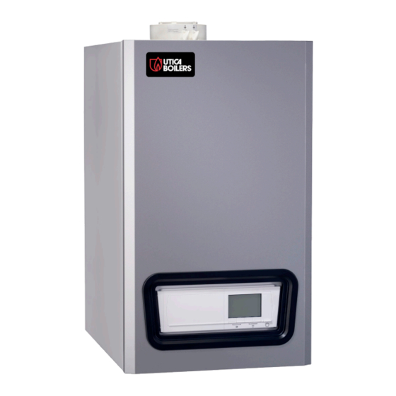
Related Manuals for UTICA BOILERS UCS-240


Summary of Contents for UTICA BOILERS UCS-240
- Page 1 Model UCS-240 CONDENSING GAS FIRED FLOOR OR WALL MOUNTED BOILER INSTALLATION, OPERATION & MAINTENANCE MANUAL Manufactured by: ECR International, Inc. 2201 Dwyer Avenue, Utica NY 13501 web site: www.ecrinternational.com P/N 240011654 Rev. C [06/08/2017]...
- Page 2 VERIFY CONTENTS RECEIVED Safety Relief Valve (Maximum 50 PSI) Fully Assembled Boiler Metal Wall Bracket Temperature Includes essential documents. TP Gauge and Safety Relief Drain Valve Gas Shutoff Valve Document Package Valve Connections Used for measuring outside Used for connecting temperature condensate piping to boiler Condensate Drain...
-
Page 3: Table Of Contents
TABLE OF CONTENTS 1 - Important Information ........5 9 - Start Up Procedure ........52 2 - Introduction ............ 6 9.1 Fill Condensate Trap with Water ....52 3 - Component Listing .......... 7 9.2 Commission Setup (Water) ......52 4 - Locating Boiler ..........8 9.3 Commission Setup (Gas) ......53 5 - Hydronic Piping .......... - Page 4 PHYSICAL DATA Dimensions Front View Table 1: Physical Data Model Width (A) 17-¾" (450mm) Height (B) 31-¹/₁₆" (763mm) Depth (C) 23" (585mm) Bracket (D) Location of Bracket on 15-⅞" (403.2mm) back of unit Top View Size 1" (25.4mm) Vent Connector Location (G) 3-¾"...
-
Page 5: Important Information
1 - IMPORTANT INFORMATION CAUTION 1. Safety Information WHAT TO DO IF YOU SMELL GAS Boiler installation shall be completed by qualified agency. See • Do not try to light any appliance. glossary for additional information. • Do not touch any electrical switch; do not use any phone in your building. -
Page 6: Introduction
2 - INTRODUCTION 2 - Introduction 2.5 Designated Use • Hot water heating boiler. 2.1 Installation shall conform to requirements of authority • Indoor installation. having jurisdiction or in absence of such requirements: • United States • Closet or alcove installation. •... -
Page 7: Component Listing
3 - COMPONENT LISTING UCS-240 Condensate trap Gas Valve Air/gas Mixer Heat exchanger Burner sight glass Manual air vent Flue sensor Coaxial flue connector Exhaust test port Intake test port Exchanger flange high limit (#4 on wire diagram) Ignition/Flame detection electrode... -
Page 8: Locating Boiler
Fire Hazard! Do not install on carpeting. Failure to Combustible Dimension Service (1)(2) Materials follow these instructions could result in death or serious injury. UCS-240 Model 4.1 Boiler Location Considerations 11-13/16" Top (A) 0" (0 cm) (300 mm) • Ambient room temperature always above 32°F (0°C) to 1-3/4"... - Page 9 4 - LOCATING BOILER FIGURE 4-1a Clearance to Combustible Materials FIGURE 4-2a Service Clearances - Boiler Front Boiler Front View Boiler Front View FIGURE 4-2b Service Clearances - Boiler Left side F L O O R FIGURE 4-1b Clearance to Combustible Materials Boiler Left Side View FIGURE 4-2c Service Clearances - Closet Installation F L O O R...
- Page 10 4 - LOCATING BOILER FIGURE 4-3 Wall Mount Bracket (Included) CAUTION Boiler weight exceeds 140 pounds (63.5 kg). Do not lift boiler onto wall without assistance. Center brackets. Avoid overhang on sides of Note wall mount bracket. Lift boiler using chassis. Using front jacket, vent piping, water or gas fittings to lift boiler may cause damage to the boiler.
-
Page 11: Hydronic Piping
5 - HYDRONIC PIPING 5.1 General Boiler rated at 50 psig (345 kPa) maximum Note • Primary/Secondary piping required. allowable working pressure. Boiler provided with • Install piping in accordance with authority having 50 psig (345 kPa) safety relief valve. jurisdiction. -
Page 12: Safety Relief Valve And Air Vent
5 - HYDRONIC PIPING FIGURE 5-2 Safety Relief Valve Discharge Piping WARNING Burn and scald hazard. Safety relief valve could discharge steam or hot water during operation. Install discharge piping per these instructions. Safety Relief Valve 5.3 Safety Relief Valve and Air Vent •... -
Page 13: Trim Piping
5 - HYDRONIC PIPING 5.5 Trim Piping • Temperature - Pressure Gauge. Install temperature pressure gauge using piping provided with boiler. See figure 5-1. If using optional floor mount pedestal install as close to boiler supply fitting as practical and visible. •... -
Page 14: Heating System And Refrigeration
5 - HYDRONIC PIPING WARNING Burn and scald hazard. Safety relief valve could discharge steam or hot water during operation. Install discharge piping per these instructions. • Route pressure relief valve discharge piping to the floor. Follow local code with respect to necessary distance to the floor. - Page 15 5 - HYDRONIC PIPING Piping Legend Illustrations are meant to show system piping Note concept only. Installer responsible for all equipment and detailing required by authority having jurisdiction. Boiler Table 4 - System Piping Configurations Single Boiler/ Zone Valves Figure 5-4 / 5-6 Primary/Secondary Pumping Multiple Boilers Zone Pumps...
- Page 16 5 - HYDRONIC PIPING FIGURE 5-4 - Primary/Secondary, Zoned, WITH ZONE VALVES, (Optional) Indirect Tank * Hot Water Supply Tempered Tank Sensor Optional Indirect BOILER DHW Tank Cold T & P Relief Water Valve to Supply Drain DHW Pump ASME Relief CH /System Valve...
- Page 17 5 - HYDRONIC PIPING FIGURE 5-5 - Primary/Secondary, Zoned, WITH ZONE PUMPS, (Optional) Indirect Tank * Hot Water Supply Tempered Tank BOILER Sensor Optional Indirect DHW Tank T & P Relief Cold Valve to DHW Pump Water Drain Supply ASME Relief Valve CH /System...
- Page 18 5 - HYDRONIC PIPING FIGURE 5-6 - Multiple Boilers Without Manifold, with Common Primary Secondary, Zone Valves and (Optional) Indirect CH/System Pump System Temperature Sensor # Boilers on Pipe PIPE # BOILERS ON Pipe Branch Size PIPE BRANCH SIZE 1-1/4 2-1/2 2½...
- Page 19 5 - HYDRONIC PIPING FIGURE 5-7 - Multiple Boilers Without Manifold, with Common Primary Secondary, Zone Pumps and (Optional) Indirect CH/System Pump System Temperature Sensor # Boilers on Pipe # BOILERS ON PIPE Pipe Branch Size PIPE BRANCH SIZE 1-1/4 2-1/2 2½...
- Page 20 5 - HYDRONIC PIPING FIGURE 5-8 - Multiple Boilers with Individual Primary Secondary, Zone Valves and (Optional) Indirect CH/System Pump 1 - SEE NOTE # BOILERS ON PIPE PIPE BRANCH SIZE System Temperature 2-1/2 Sensor CH/System Pump 2 - SEE NOTE BOILER BOILER...
-
Page 21: Combustion Air And Vent Piping
6 - COMBUSTION AIR AND VENT PIPING • Support piping in accordance with pipe manufacturer's WARNING instruction and authority having jurisdiction. In absence Fire, explosion, and asphyxiation hazard. Improper of manufacturer's instruction use pipe hooks, pipe straps, installation could result in death or serious brackets, or hangers of adequate and strength located injury. -
Page 22: Approved Venting Materials
6 - COMBUSTION AIR AND VENT PIPING B. Approved Polypropylene Manufacturers: WARNING Must comply with UL 1738 or ULC S636. The following Manufacturer recommends this condensing boiler manufacturers have been evaluated: be vented with approved polypropylene venting • Natalini material. Use only materials listed below for vent •... -
Page 23: Concentric Venting Instructions
6 - COMBUSTION AIR AND VENT PIPING FIGURE 6-1 WARNING • Covering non-metallic vent pipe and fittings with thermal insulation shall be prohibited. • Use of cellular core PVC for venting flue gas could result in death, or serious injury. •... - Page 24 6 - COMBUSTION AIR AND VENT PIPING • Remove waste from both vents (flue and air). Verify cut FIGURE 6-4 - Steel Strapping or Equivalent ends are square and free from burrs. Insert flue back into intake air vent and pass them through hole in wall. •...
- Page 25 6 - COMBUSTION AIR AND VENT PIPING FIGURE 6-5 - Maximum Equivalent Length Maximum Length = L 21’ (6.4 m) 17' 8" (5.4 m) 21’ (6.4 m) 14’ 5" (4.4 m) 17'8" (5.4 m) FIGURE 6-6 (A-H) Concentric Vent Screw Placement - See Figure 6.7 Fasten two screws through outer intake pipe behind the Before securing screws, verify pipe is pushed in Note...
-
Page 26: Two Pipe Polypropylene System
6 - COMBUSTION AIR AND VENT PIPING 6.5 Two Pipe Polypropylene System FIGURE 6-8 - Two Pipe Polypropylene System Adapter Two pipe venting allows for exhaust flue and intake flue to be separated from each other. Fresh air may be drawn in at a different area from where the flue terminal is located. - Page 27 6 - COMBUSTION AIR AND VENT PIPING Spring Clamp Instructions - See Figure 6-11 FIGURE 6-11 - Spring Clamp Manufacturer recommends use of a spring clamp at every push-fit gasket connection when using a polypropylene vent. Follow vent manufacturer instructions or, if unavailable, below when installing spring clamps: •...
-
Page 28: Venting Configurations
6 - COMBUSTION AIR AND VENT PIPING 6.6 Venting Configurations Use of vent covers may cause freezing. If using Note Various venting configurations can be applied to this boiler. vent covers overall vent length must be considered. For guidance see Venting Configuration Table 5A and Failure to heed this information may compromise corresponding figures. - Page 29 6 - COMBUSTION AIR AND VENT PIPING FIGURE 6-14 Two Pipe Roof Vent 12" (205mm) Min. horizontal separation between combustion air intake and vent 12" (205mm) Min. of same appliance. 12" (205mm) Min. 84" (2134mm) Max. 12" (305mm) Min. 15"...
- Page 30 6 - COMBUSTION AIR AND VENT PIPING FIGURE 6-17 Side Wall Venting Terminal w/T-Terminal Configurations of single pipe vent with flue on the Note sidewall, requires a tee as the vent terminal. See figures 6-17, 6-19 and 6-21 12" (305mm) Min. Separation of Combustion Air and Vent shall be maintained.
- Page 31 6 - COMBUSTION AIR AND VENT PIPING FIGURE 6-20 Flue on Roof, Indoor Combustion Air Maintain 12"(305mm) US Vent (18"(457mm) Canada) minimum clearance above Combustion air and Vent Piping Length Page 26. highest anticipated snow level maximum 24" (610mm) above roof Combustion 24"...
-
Page 32: Side Venting Terminal Requirements Of
6 - COMBUSTION AIR AND VENT PIPING 6.7 Side Venting Terminal Requirements of : • USA - National Fuel Gas Code, ANSI Z223.1/NFPA 54. • Canada - Natural Gas and Propane Installation Code, CAN/CSA B149.1 Venting terminal from doors and windows See figure 6-22 Venting terminal from forced air inlet of other appliances See figure 6-23... - Page 33 6 - COMBUSTION AIR AND VENT PIPING FIGURE 6-25 Keep vent termination 3’ minimum Vegetation, (914mm) away from vegetation. Position Plants & termination where vent vapors will not Shrubs damage plants/shrubs or air conditioning equipment. Termination Vent termination US only - 4’ (1.2m), Meters, Canada - 6' (1.9m) horizontally from, no Regulators,...
- Page 34 6 - COMBUSTION AIR AND VENT PIPING FIGURE 6-27 Flue Termination Location Vent Termination Minimum Clearances CANADA Clearance above grade, veranda, porch, deck, or balcony 12" (305mm) 12" (305mm) Clearance to window or door that may be opened 12" (305mm) 3 ft.
-
Page 35: Condensate Piping
6 - COMBUSTION AIR AND VENT PIPING FIGURE 6-28 Condensate Drain 6.8 Condensate Piping • Use materials acceptable to authority having jurisdiction. In absence of such authority: • USA - PVC or CPVC per ASTM D1785/D2845 Cement or primer per ASME D2564 or F493. Do not glue cap •... -
Page 36: Multiple Boiler Venting - General
6 - COMBUSTION AIR AND VENT PIPING FIGURE 6-29 Correctly Mounted Piping WARNING Asphyxiation hazard. DO NOT use screws to secure piping together. Failure to follow these instructions could cause death or serious injury. 6.9 Multiple Boiler Venting - General •... - Page 37 6 - COMBUSTION AIR AND VENT PIPING FIGURE 6-32 Secure Clamp around Flue Adapter Connect boiler flue adapter to flue damper for each boiler in cascade system. Ensure flue adapters allow for 3° or 2 in. per 3 ft. slope of horizontal collectors back towards condensate collector.
-
Page 38: Multiple Boiler Venting - Layout
6 - COMBUSTION AIR AND VENT PIPING 6.11 Multiple Boiler Venting - Venting Layout Available pressure at flue outlet is 0.40" w.c. (100pa) Flue Outlet Maximum Vertical Length Heat input Heat input Number of 6 in / 8 in * 6 in (150 mm) 8 in (200 mm) BTUH... - Page 39 6 - COMBUSTION AIR AND VENT PIPING A. Single Line System System consisting of boilers arranged in line each connected to common exhaust manifold. FIGURE 6-35 2 in. per 3 ft. 4 in. (50.0 mm per 1.0 m) 3° B. Back to Back System This system consists of boilers installed back to back connected to a common exhaust manifold.
-
Page 40: Multiple Boiler Venting - Parameter Setting
6 - COMBUSTION AIR AND VENT PIPING C. Double Line System This system consists of boilers installed on two lines, connected to a common exhaust manifold. FIGURE 6-37 2 in. per 3 ft. 4 in. (50.0 mm per 1.0 m) 3°... -
Page 41: Gas Supply Piping
• Size and install gas piping system to provide sufficient gas Gas Connection supply to meet maximum input at not less than minimum supply pressure. UCS-240 requires a gas rate of 242.59 ft3/h (6.87 m3/h) for Natural Gas (Gas A) and 95.04 ft3/h Use two (2) wrenches when tightening and Note (2.69 m3/h) for Liquid Propane Gas (Gas E). - Page 42 7 - GAS SUPPLY PIPING FIGURE 7-3 Manual Main Gas Shutoff Valve Outside DANGER Boiler Jacket Fire Hazard. Do not use matches, candles, open flames, or other methods providing ignition source. Failure to comply will result in death or serious injury.
-
Page 43: Electrical Connections
8 - ELECTRICAL CONNECTIONS WARNING 8.1 General Electrically bond boiler to ground in accordance with Electrical shock hazard. Turn OFF electrical power requirements of authority having jurisdiction. Refer to: supply at service panel before making electrical • USA- National Electrical Code, ANSI/NFPA 70. connections. -
Page 44: Access To Connection Block
8 - ELECTRICAL CONNECTIONS 8.4 Access To Connection Block FIGURE 8-2 Remove Front Panel Unscrew two screws located under front panel a quarter turn. Remove panel. Guide controller or thermostat wire through round grommet(s) on right side of boiler's bottom plate right. Tilt control box forward by opening holding clips located on each side of boiler. -
Page 45: Shutdown Input
8 - ELECTRICAL CONNECTIONS FIGURE 8-3 Shutdown Input 8.6 Shutdown Input • Boiler has a shutdown input, input is on BL terminals of control board. • Only suitable for potential free contacts. • When using this input remove jumper cable. •... - Page 46 8 - ELECTRICAL CONNECTIONS FIGURE 8-7 Analog Temperature Based Control Analog Temperature-Based Control - 0 - 10 V signal controls boiler supply temperature between 32ºF (0ºC )and 194ºF (90ºC). Control modulates on basis of supply temperature, heat output varies between minimum and maximum values based on supply temperature set point calculated by the controller.
- Page 47 8 - ELECTRICAL CONNECTIONS Connection Option For PCB (SCU-S02) FIGURE 8-9 Analog Output 0-10V If boiler is fitted with control PCB (SCUS02) it will automatically be recognized by the automatic boiler control. If removing this PCB boiler will show fault code E38. To prevent this fault, auto-detect must be done after removing the PCB.
-
Page 48: Outdoor Temperature Sensor
8 - ELECTRICAL CONNECTIONS 8.9 Outdoor Temperature Sensor FIGURE 8-10 Outdoor Temp Sensor Outdoor Temperature Flow Temperature P1 - Supply temperature (maximum) P25 - Supply temperature (minimum) P26 - "WWSD" (Warm Weather Shutdown) P27 - Outdoor temperature (default) If outdoor temperature sensor is connected, heating curve can be adjusted. -
Page 49: Dhw Indirect Water Heater
8 - ELECTRICAL CONNECTIONS 8.11 DHW Indirect Water Heater FIGURE 8-12 Indirect Water Heater Thermostat Connect DHW indirect tank sensor or thermostat (TS) to "T dhw" terminals on control board. 8.12 Frost Protection Frost protection in combination with ON/Off thermostat. •... - Page 50 8 - ELECTRICAL CONNECTIONS FIGURE 8-14 Example Of Hydronic Circuit With DHW Indirect Water Heater • Connect Indirect tank sensor to Tdhw terminals as described in section 8.11. • Connect CH (Central Heating) pump on terminal N-L "Pump" of control PCB (SCU-02) see section 8.8. •...
- Page 51 8 - ELECTRICAL CONNECTIONS FIGURE 8-16 Wiring Diagram P/N 240011654, Rev. C [06/08/2017]...
-
Page 52: Start Up Procedure
9 - START UP PROCEDURE FIGURE 9-1 Condensate Drain Assembly 9.1 Fill Condensate Trap with Water WARNING Pour approximately Asphyxiation hazard! Fill condensate trap before 1 cup of water starting boiler to avoid combustion products escaping into flue way of boiler. -
Page 53: Commission Setup (Gas)
9 - START UP PROCEDURE FIGURE 9-2 Gas Valve WARNING Fire, explosion, and asphyxiation hazard! Boiler is set for natural gas from the factory. If propane is to be used the gas valve must be adjusted before turning boiler on. Failure to follow these instructions could result in death or serious injury. -
Page 54: Control Panel
9 - START UP PROCEDURE 9.5 Control Panel Display [Escape] or RESET button Heating Temperature or [-] button DHW temperature or [+] button [Enter] or cancel lock-out button Setup buttons (press the 2 and 3 buttons simultaneously) [Menu] buttons (press the 4 and 5 buttons simultaneously) ON/OFF switch Symbols... -
Page 55: Deaeration Function
9 - START UP PROCEDURE 9.6 Deaeration Function FIGURE 9-3 AERATOR Control performs the Deaeration function at initial Note start and after a reset of a locking error and after power up. Before starting boiler deaeration function must be performed. Rotate black cap on deaerator, located inside the boiler, counter clockwise ... -
Page 56: Commissioning
Verify there are no gas leaks. The temperature of combustion air must be measured on the air intake test port (B) by inserting the measurement sensor Natural Gas Propane approximately 3-3/16" (80.00 mm) (C) for the UCS-240. Venturi Nozzle Venturi Nozzle 1 ³/₁₆... -
Page 57: Combustion Setup (High-Fire)
9 - START UP PROCEDURE 9.10 Combustion Setup (High-Fire) 9.11 Combustion Setup (Low-Fire) • Unscrew exhaust port plug at exhaust flue test port. • Unscrew exhaust port plug at exhaust flue test port. • Insert combustion analyzer into exhaust flue test port. •... -
Page 58: User Level Parameters
9 - START UP PROCEDURE FIGURE 9-9 - User Level Parameters 9.13 User Level Parameters Parameters P1 to P8 can be adjusted by end user to meet heating system and DHW comfort needs. Modification of factory settings may be detrimental to operation of the boiler. -
Page 59: Parameters Settings
With these settings, most heating systems operate correctly; however, installer can adjust parameters according to their own preferences. Factory Setting Parameter Description Adjustment Range UCS-240 Max flow temperature during CH mode 68 to 194ºF 176°F/80°C (Set temperature) 20 to 90ºC 104 to 149ºF... - Page 60 9 - START UP PROCEDURE Parameters Settings - Continued Factory Setting Parameter Description Adjustment Range UCS-240 Clima point heating curve -22 to 32ºF outside temperature (Only -30 to 0ºC with an outdoor temperature 241= 5ºF/-15ºC sensor) Pump control, CH minimum...
-
Page 61: Factory Setting
9 - START UP PROCEDURE Parameters Settings - Continued Factory Setting Parameter Description Adjustment Range UCS-240 Modulate back when dT > 41 to 140ºF 140º/60ºC this parameter 5 to 60ºC DHW stabilization time 10 to 100 seconds 0 = Metric... -
Page 62: Reading Measured Values
9 - START UP PROCEDURE 9.16 Reading Measured Values The following current values can be read from the information menu • St = State • Su = Sub-status • t1 = Supply temperature ºF/ºC • t2 = Return temperature ºF/ºC •... -
Page 63: Status And Sub-Status
9 - START UP PROCEDURE 9.17 Status And Sub-Status The information menu gives the following status and sub-status information: State (St) Sub-status (Su) Rest Rest Short pre-purge of the fan Control three-way valve Boiler starts (Demand for heat) Start pump sw checks sensor temperatures before the burner starts Open flue gas damper/external gas valve Increase fan speed... -
Page 64: Return To The Factory Settings
9 - START UP PROCEDURE 9.18 Return To The Factory Settings • Press the two Menu buttons simultaneously and then (+) button until symbol flashes on the menu bar. • Select the INSTALLER menu using . "COdE" appears on the display. •... -
Page 65: Operating Instructions
10 - OPERATING INSTRUCTIONS FOR YOUR SAFETY READ BEFORE OPERATING 10.2 OPERATING INSTRUCTIONS Stop! Read Safety information above. WARNING • Set thermostat to lowest setting. If you do not follow these instructions • Turn "OFF" all electrical power to appliance. exactly, a fire or explosion may result causing property damage, personal injury or loss of •... -
Page 66: General Maintenance And Cleaning
11 - GENERAL MAINTENANCE AND CLEANING FIGURE 11-1 Sight Glass DANGER Before servicing, turn off electrical power to boiler at service switch. Close manual gas valve to turn Sight Glass gas supply OFF to boiler. Failure to comply will result in death or serious injury. CAUTION Label all wires prior to disconnection when servicing controls. - Page 67 11 - GENERAL MAINTENANCE AND CLEANING 11.2 Annual Shut Down Procedure • Circulator pump and combustion air blower motor furnished with boiler are permanently lubricated from factory and • Follow instructions “To Turn Off Gas To Appliance” unless require no further lubrication. Lubricate field sourced boiler is also used to supply domestic hot water.
- Page 68 11 - GENERAL MAINTENANCE AND CLEANING 11.4 Maintenance And Routine Servicing WARNING Check and service boiler as necessary. Following service procedures must be performed Frequency of servicing will depend upon installation conditions by qualified service agent. Boiler owner shall not and usage, manufacturer recommends annually.
- Page 69 11 - GENERAL MAINTENANCE AND CLEANING 11-1 Electrodes DANGER Before servicing, turn off electrical power to boiler at service switch. Close manual gas valve to turn gas supply OFF to boiler. Failure to comply will result in death or serious injury. 11.6 Draining the Boiler •...
-
Page 70: Ratings And Capacities
Number (MBH) (1)(2) Maximum Minimum UCS-240 95.0 1000 Btu/hr (British Thermal Units Per Hour) Heating Capacity and AFUE (Annual Fuel Utilization Efficiency) are based on DOE (Department of Energy) test procedures. Net AHRI Ratings based on piping and pickup allowance of 1.15. Contact Technical Support before selecting boiler for installations having unusual piping and pickup requirements, such as intermittent system operation, extensive piping systems, etc. -
Page 71: Trouble Shooting
13 - TROUBLE SHOOTING 13.1 Troubleshooting This boiler is fitted with an electronic regulation and control unit. Control system is a microprocessor, Comfort Master©, which controls and protects the boiler. If a fault is detected anywhere in the boiler, boiler will lock out and display will show the fault code as follows: Red flashing display: •... - Page 72 13 - TROUBLE SHOOTING Error Code Table Error Description Probable Causes Checking/Solution Code Replace the sensor if necessary Purge the air in the Temperature difference Sensor fault heating system between the supply and Sensor not/poorly connected Check for water circulation (direction, pump, valves) return temperatures too No circulation Check that the sensors are operating correctly...
-
Page 73: Shutdowns And Lock-Outs
13 - TROUBLE SHOOTING Error Code Table Error Description Probable Causes Checking/Solution Code Check whether the SU PCB has been correctly fitted in Communication error with Bad connection connector on PCU PCB SU PCB Communication error with Bad connection Check the wiring Replace SCU PCB SCU PCB Defective SCU PCB Bad connection... - Page 74 13 - TROUBLE SHOOTING Shutdown Code Table Shut- down Description Probable Causes Checking/Solution Code Parameter error on the PSU Su:0 Parameter error Reset df and dU Restore parameters Maximum supply Non-existent or insufficient Check the circulation (direction, pump, valves) Su:1 temperature exceeded circulation / sensor error Reasons for the heat demand...
- Page 75 13 - TROUBLE SHOOTING Shutdown Code Table Shut- down Description Probable Causes Checking/Solution Code Su:20 Identification running No action required Communication error with Check whether SU PCB has been correctly fitted in the Su:21 Bad connection SU PCB connector on SU PCB Purge gas supply to remove air Check gas valve is fully opened No flame during...
-
Page 76: Error History
13 - TROUBLE SHOOTING 13.3 Error History Boiler control is equipped with error memory which, records last 16 errors. In addition to storing error codes, the following data is also saved: • Number of times that the error occurred: (n:xx). •... -
Page 77: Optional Sensors
13 - TROUBLE SHOOTING 13.5 Optional Sensors Outdoor Air Sensor, if used. A. Boiler automatically recognizes sensor when used. B. See Chart 1 for sensor data. Sensor part number BD710487302V C. Locate outdoor sensor to protect against wind and direct sunlight. Mounting instructions provided with sensor. D. -
Page 78: Troubleshooting Chart 1
13 - TROUBLE SHOOTING Troubleshooting Chart 1 E02 - Supply Sensor Short E03 - Supply Sensor Open E04 - Heat Exchanger Temp. E05 - Heat Exchanger Temp. E06 - Return Sensor Short E07 - Return Sensor Open E08 - Low Return Temp. E09 -High Return Temp. -
Page 79: Troubleshooting Chart 2
13 - TROUBLE SHOOTING Troubleshooting Chart 2 E16 - False Flame Signal Turn Off All Heat Calls Inspect Burner through sight glass. Is flame present? Initiate heat call. Check CO Replace Gas at high fire is 9.1-9.5% Valve Out of Range In Range Adjust Gas Mixture See Section 9. -
Page 80: Troubleshooting Chart 3
13 - TROUBLE SHOOTING Troubleshooting Chart 3 E12 - High Temperature Is High Limit Jumper Plug in Place? Is external Re-install plug High Limit Switch off? NO or N/A Check switches 4 and 5 in wire diagram. Both electrical connected and continuity? Reset Switch Does heat... -
Page 81: Troubleshooting Chart 4
13 - TROUBLE SHOOTING Troubleshooting Chart 4 E10, E11 - Temperature Difference Between Supply and Return Too Great E35 - Supply and Return Sensors Reversed Is return line warmer than supply line? Error Code is Check water pressure. Is water accurate. -
Page 82: Troubleshooting Chart 5
13 - TROUBLE SHOOTING Troubleshooting Chart 5 E14 - Burner Start Up Failures Is this a new boiler on first startup? LP installation? Is the gas shutoff valve closed? LP Conversion Kit installed? Check all wires including Open the gas shutoff igniter and gas valve are valve Install... -
Page 83: Troubleshooting Chart 6
13 - TROUBLE SHOOTING Troubleshooting Chart 6 E36 - Burner Flame Loss LP Installation? LP Conversion kit installed? Is gas shutoff valve fully open? Install LP Conversion Kit Check all wires including Open Gas shutoff valve. igniter and gas valve are connected and tight. -
Page 84: Troubleshooting Charts 7 & 8
13 - TROUBLE SHOOTING Troubleshooting Chart 7 E34 - Fan Fault Check all wires including blower valve are connected and tight Check venting for Connect all obstruction (both inlet and wires and exhaust) assure secure Replace Blower Clear Vent Assembly Obstruction Troubleshooting Chart 8 E39 - Shutdown Input In Locked Out Mode... -
Page 85: Troubleshooting Chart 9
13 - TROUBLE SHOOTING Troubleshooting Chart 9 E40 - HRU/URC Unit test error Is HRU terminal being used on the auxiliary SCU board (see section 8) ? Is wiring connection to HRU Is wiring connection from terminal secure? SCU board to main board secure? Fix Wiring Fix Wiring... -
Page 86: Troubleshooting Chart 10
13 - TROUBLE SHOOTING Troubleshooting Chart 10 Note: This error code refers to the onboard low water E42 - Low Water Pressure pressure switch, not any field installed external low water cutoff device. Check system water pressure with tridicator or other device. Is water pressure at least 15 psig? The error code is Check wire harness... -
Page 87: Troubleshooting Chart 11
13 - TROUBLE SHOOTING Troubleshooting Chart 11 E43 - No Water Temperature Difference During Operation Start Boiler. Is supply line warmer than return line? Onboard pump operating properly? Replace Pump Check wire plugs are Possible air in the securely connected to system. -
Page 88: Temperature - Resistance Chart
13 - TROUBLE SHOOTING Figure 13-1 Temperature-Resistance Chart for Supply and Return Temperature Sensors T (°C) T (°F) R (Ohm) 309396 171840 98932 58879 36129 22804 14773 12000 9804 6652 4607 3252 2337 1707 1266 P/N 240011654, Rev. C [06/08/2017]... -
Page 89: Glossary
14 - GLOSSARY • APPLIANCE - Device to convert gas into energy; term • DOMESTIC - Relating to household usage as opposed to includes any component, control, wiring, piping or tubing commercial usage. required to be part of the device. •... - Page 90 15 - GLOSSARY • PRESSURE TEST - Operation performed to verify gas tight integrity of gas piping following its installation or modification. • PURGE - To free gas conduit of air or gas, or mixture of gas and air. • PURGE TIME - Period of time intended to allow for dissipation of any unburned gas or residual products of combustion.
- Page 91 NOTES P/N 240011654, Rev. C [06/08/2017]...
- Page 92 IMPORTANT In accordance with Section 325 (f) (3) of the Energy Policy and Conservation Act, this boiler is equipped with a feature that saves energy by reducing the boiler water temperature as the heating load decreases. This feature is equipped with an override which is provided primarily to permit the use of an external energy management system that serves the same function.