
Related Manuals for MasterCraft 055-6761-2


Summary of Contents for MasterCraft 055-6761-2
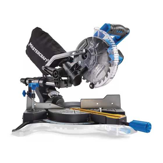
- Page 1 055-6761-2 SLIDING COMPOUND MITRE SAW INSTRUCTION IMPORTANT: MANUAL Please read this manual carefully before using this mitre saw and save it for reference...
- Page 2 TABLE OF CONTENTS SPECIFICATIONS SAFETY GUIDELINES KEY PARTS DIAGRAM ASSEMbLY AND ADJUSTMENTS OPERATING INSTRUCTIONS MAINTENANCE TROUbLESHOOTING ExPLODED VIEW PARTS LIST WARRANTY NOTE: If any parts are missing or damaged, or if you have any questions, please call our toll-free helpline at 1-800-689-9928.
- Page 3 055-6761-2 | contact us 1-800-689-9928 SPECIFICATIONS SAFETY GUIDELINES Motor 120V AC, 60 Hz, 9.5A • Keep guards in place and in working order. Speed 5000 RPM (no load) • Remove adjusting keys and wrenches. Form habit of checking to see that keys and adjusting blade 7 1/4”...
- Page 4 055-6761-2 | contact us 1-800-689-9928 • Never stand on tool. Serious injury could occur if the tool is tipped or if something unintentionally • Avoid body contact with grounded surfaces such as pipes, radiators, ranges and refrigerators. There is an increased risk of electric shock if your body is grounded.
- Page 5 055-6761-2 | contact us 1-800-689-9928 • Be sure to turn the tool off and wait for the saw blade to stop before moving the workpiece or • Never hold a workpiece by hand if it is too small to be clamped. Always keep your hands clear changing settings.
- Page 6 055-6761-2 | contact us 1-800-689-9928 Description Description condition that may affect the tool’s operation. A guard or other part that is damaged should be properly Switch handle repaired or replaced by a qualified person. Mitre stop locking lever...
- Page 7 055-6761-2 | contact us 1-800-689-9928 REMOVING AND INSTALLING THE BLADE Description Description Spindle lock Sliding carriage lock knob Removing blade (Fig. 1 to 4) Blade Bevel lock knob • Unplug the tool from the power source. Motor Bevel scale...
- Page 8 055-6761-2 | contact us 1-800-689-9928 INSTALLING THE DUST BAG • Place the out flange against the blade and on the (Fig. 5) arbor. Thread the blade bolt onto the arbor in a • Squeeze the metal collar wings on the dust bag.
- Page 9 055-6761-2 | contact us 1-800-689-9928 • If the blade is not 90° square with the table, loosen the bevel lock knob, tilt the cutting head to the left, Mitre Angle Pointer Adjustment (Fig. 6) loosen the locknut (3) and turn the bevel angle adjustment bolt (4) in or out with a 3 mm hex wrench •...
- Page 10 055-6761-2 | contact us 1-800-689-9928 UNLOCKING AND LOCKING THE CUTTING • Loosen the lock nut (1) to free the depth screw (2). HEAD (Fig. 12) • Move the cutting head down until the blade extends just 5/16” (0.8 cm) below the table insert.
- Page 11 055-6761-2 | contact us 1-800-689-9928 BENCH MOUNTING MITRE CUT (Fig. 14) (Fig. 17) This tool should be bolted with four bolts to a level and • When a mitre cut is required, unlock the table by stable surface using the bolt holes (1) provided in the tool’s turning the mitre handle (1) counter-clockwise.
- Page 12 055-6761-2 | contact us 1-800-689-9928 SLIDING CARRIAGE SYSTEM SETTING CUTTING DEPTH (Fig. 20) (Fig. 22) • For chop cutting operations on small workpieces, The depth of cut can be preset for even and repetitive slide the cutting head completely toward the rear of shallow cuts.
- Page 13 055-6761-2 | contact us 1-800-689-9928 CUTTING WARPED MATERIAL CUTTING CROWN MOULDING (Fig. 27, 28) (Fig. 24) When cutting warped material, be sure that the convex Your compound mitre saw is suited for the difficult task of side is against the fence. If the workpiece is placed with cutting crown moulding.
- Page 14 055-6761-2 | contact us 1-800-689-9928 CROWN MOULDING CHART 52/38° CROWN MOULDING 45/45° CROWN MOULDING To aid in the correct setting, the compound angle setting chart below has been Angle Between Mitre Setting Bevel Setting Mitre Setting Bevel Setting provided.
- Page 15 055-6761-2 | contact us 1-800-689-9928 SAWDUST 52/38° CROWN MOULDING 45/45° CROWN MOULDING Periodically, sawdust will accumulate under the table and base. This could cause difficulty in the movement Angle Between of the table when setting up a mitre cut. Frequently blow out or vacuum up the sawdust.
- Page 16 055-6761-2 | contact us 1-800-689-9928 This will avoid a break-in period that reduces motor performance and increases wear. SUGGESTED COrrECTIVE PrOBLEM PrOBABLE CAUSE LUBRICATION (Fig. 30) ACTION All the motor bearings in this tool are lubricated with a...
- Page 17 055-6761-2 | contact us 1-800-689-9928 1 1 1 MASTERCRAFT 7 1/4” (18.4 CM) SLIDING MITRE SAW ® When servicing the Mastercraft ® Sliding Compound Mitre Saw, use only Mastercraft ® replacement parts. The use of any other parts may cause damage to the product. All servicing of the mitre saw should be performed by a qualified service technician.
- Page 18 055-6761-2 | contact us 1-800-689-9928 Description Description Description Description Motor housing Half-round head screw Hex screw Big torsional spring Brush holder Cuting depth stop plate Fence Brand label Coil spring Location pin Base Dust bag Carbon brush O-ring...
- Page 19 3-YEAR LIMITED WARRANTY Additional limitations This Mastercraft product is guaranteed for a period of 3 years from the date of original retail purchase This warranty applies only to the original purchaser and may not be transferred. Neither the retailer nor...