Marantz SR5006 Model Information
Integrated network av receiver
Hide thumbs
Also See for SR5006:
- Service manual (194 pages) ,
- Owner's manual (146 pages) ,
- Getting started manual (16 pages)
Advertisement
Table of Contents
- 1 Front Panel
- 2 Main Display (1 of 2)
- 3 Main Display (2 of 2)
- 4 Rear Panel
- 5 Remote Control (1 of 2)
- 6 Remote Control (2 of 2)
- 7 MARANTZ USA LIMITED WARRANTY (1 of 2)
- 8 Specifications - Audio Section
- 9 Specifications - Video Section, Tuner Section, General Section
- 10 Specifications - Dimensions, Weight
- 11 SR5006 - Protection History Display Mode (1 of 3)
- 12 SR5006 - Protection History Display Mode (2 of 3)
- 13 SR5006 - Protection History Display Mode (3 of 3)
- Download this manual
See also:
Owner's Manual
Model Information
Index
Front Panel
Rear Panel
Remote Control
Warranty
Reset Procedure
Accessories
Protection History
Display Mode
Upgrades/Updates
Product Specifications
I/R Codes
NOTE:
This edition is missing the link to the IR codes................................................................................ 12/12/2016
MODEL:
Model Information
INTEGRATED NETWORK AV RECEIVER
SR5006
MI121216E3-1
Advertisement
Table of Contents

Related Manuals for Marantz SR5006


Summary of Contents for Marantz SR5006
- Page 1 MODEL: SR5006 Model Information Index Model Information Front Panel INTEGRATED NETWORK AV RECEIVER Rear Panel Remote Control Warranty Reset Procedure Accessories Protection History Display Mode Upgrades/Updates Product Specifications I/R Codes NOTE: This edition is missing the link to the IR codes…………………………………………………………………….. 12/12/2016...
-
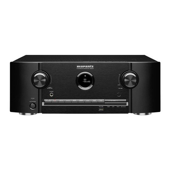
Page 2: Front Panel
Front Panel Power indicator AUX INPUT connectors DISPLAY button Power indicator status in standby mode Remove the cap covering the connectors • Red: Normal standby STATUS button when you want to use them • Orange: ZONE SELECT button • When “HDMI Control” is set to “On” ZONE2 ON/OFF button •... -
Page 3: Main Display (1 Of 2)
Main Display (1 of 2) Main display The input source name, sound mode, setting values and other information are displayed here. Standard display Tuner display These light according to the reception conditions when the input source is set to “TUNER”. Master volume indicator Input source indicator The currently selected input source name is displayed. -
Page 4: Main Display (2 Of 2)
Main Display (2 of 2) Sleep timer indicator ZONE2 power on display This lights when the sleep mode is selected. This lights up when ZONE2 (separate room) power is turned on. HOME MAIN DISPLAY (1 of 2) REAR PANEL... -
Page 5: Rear Panel
Rear Panel HDMI connectors Digital audio connectors RC-232C connector (DIGITAL AUDIO IN) FM antenna terminal (ANTENNA) Network connector (NETWORK) Analog audio connectors FLASHER IN jack PRE OUT connectors Used when using a control BOX or other such control devices to VIDEO connectors control this unit. -
Page 6: Remote Control (1 Of 2)
Remote Control (1 of 2) LEARN indicator SET button SOURCE power button Display button (DISP) PURE DIRECT button Internet radio button Input source select buttons Zone mode buttons (Z2, Z3) Source select menu button SURROUND button Source select buttons (SOURCE ) AMP MENU button SHIFT/TOP MENU button Cursor buttons () -
Page 7: Remote Control (2 Of 2)
Remote Control (2 of 2) Clear (CLR)/MEMORY button TUNING buttons (+, –) Remote control signal transmitter SEND indicator Power buttons (ON, STANDBY PARTY button SPEAKER A/B button Preset channel buttons (P1 – P3) AMP button Muting button (MUTE) Volume control buttons (VOLUME +, –) STATUS OSD button SEARCH/Information (INFO) button ENTER button... -
Page 8: Marantz Usa Limited Warranty (1 Of 2)
Length of Non-Transferable Warranty This warranty on your Marantz product which is distributed and warranted by Marantz America Inc. remains in effect for the following periods from the date of the original consumer purchase from an AUTHORIZED DENON ELECTRONICS (USA), LLC DEALER. - Page 9 How you can get service If your unit needs service, contact Marantz customer service by calling 201-762-6666. We will advise you of the name and location of one or more authorized Marantz service stations from which service can be obtained. Please do not return your unit to the factory without prior authorization.
- Page 10 Reset “ZONE SELECT” “DISPLAY” button Power/Standby button button Reset procedure: With the power off, press and hold the “DISPLAY” button, “ZONE SELECT” button, and “POWER” button simultaneously on the AVR for a few seconds until “INITIALIZED” appears on the AVR’s display Resetting the micro is a procedure used to "reboot"...
- Page 11 Accessories Sound Remote Control Sound Calibration (RC014SR) Calibration Microphone Microphone Stand (ACM1H) 307010092004M 324810004004M 963549101000D $16.82 AM Loop FM Indoor Power Cord) Antenna Antenna 90M-ZA000260R $8.99 00D9600187308 $7.79 90M-ZC000470R $30.64 Safety CD ROM Instructions Owner’s Manual Warranty Notes on Radio Quick Start (For North Guide...
- Page 12 FAQ’s ( 1 of 2) HOME ACCESSORIES FAQ’s 2...
- Page 13 FAQ’s (2 of 2) HOME FAQ’s 1 UPGRADE...
- Page 14 Dolby Atmos and DTS:X surround sound technologies dispense with channel-based coding in favor of object-based coding, giving the sound designer the ability to precisely place sounds anywhere in the 3-dimensional space. The SR5006, features the ability to connect a 5.1 surround sound speaker system and 4 additional overhead speakers (or 4 additional Dolby Atmos elevation speakers) for the ultimate home cinema experience.
- Page 15 Server is busy Login failed To Check for Firmware Update from the Marantz server when the unit is connected to the internet via the Ethernet port (When Firmware Notification is turned off). Press “SETUP” and select “GENERAL” and then select “FIRMWARE” followed by “UPDATE” and finally, select “CHECK FOR UPDATE”.
-
Page 16: Specifications - Audio Section
Specifications – Audio Section Audio section Front 100 W + 110 W (8 Ω/ohms, 20 Hz – 20 kHz with 0.08 % T.H.D.) Center 100 W + 110 W (8 Ω/ohms, 20 Hz – 20 kHz with 0.08 % T.H.D.) Rated output Surround 100 W + 110 W (8 Ω/ohms, 20 Hz –... -
Page 17: Specifications - Video Section, Tuner Section, General Section
Specifications - Video section, Tuner Section, General Section Video section Input/output level and impedance 1 Vp-p, 75 Ω/ohms Standard video connectors Frequency response 5 Hz -10MHz, 0, - 3dB Y signal 1 Vp-p, 75 Ω/ohms Input/output level and impedance PB/CB signal 0.7 Vp-p, 75 Ω/ohms Color component video connector PR/CR signal... -
Page 18: Specifications - Dimensions, Weight
Specifications – Dimensions, Weight Dimensions section (Unit : inch/mm) Weight: 23 lbs 5.9 oz (10.6 kg) HOME SPECIFICATIONS - SPECIFICATIONS - VIDEO – Protection History Display AUDIO TUNER – GENERAL Mode (Front Panel Buttons) -
Page 19: Sr5006 - Protection History Display Mode (1 Of 3)
SR5006 - Protection History Display Mode (1 of 3) Model Information Index Protection History Mode records and displays an event in which the THERMAL, CURRENT, ASO or DC protection was activated. POWER PURE DIRECT INTERNET RADIO ONE TOUCH PLAY Procedure to enter the “Protection History Display Mode”. -
Page 20: Sr5006 - Protection History Display Mode (2 Of 3)
SR5006 - Protection History Display Mode (2 of 3) Model Information Index 1. If no protections have occurred, “No Protect” is displayed 2. if last protection was ASO, “ASO” is displayed. Cause: A short circuit occurred between the speaker terminals, or speakers with an impedance outside the rating were connected. If the power is turned on during this abnormality, protection is activated after around 5 seconds and the power is turned off. -
Page 21: Sr5006 - Protection History Display Mode (3 Of 3)
SR5006 - Protection History Display Mode (3 of 3) Model Information Index Clearing the Protection History If the unit is in “Protection History Display Mode”, just press and hold the “PURE DIRECT” button for 3 seconds. Note: If you do not mind erasing your settings from this unit, you can also “Initialized/Micro Reset the unit to clear the Protection History from... - Page 22 The End NOTE: This edition is missing the link to the IR Codes……………………………………………………………………...12/12/2016 HOME...