Advertisement
Quick Links
Advertisement

Related Manuals for Danfoss BasicPlus2 WT-D


Summary of Contents for Danfoss BasicPlus2 WT-D
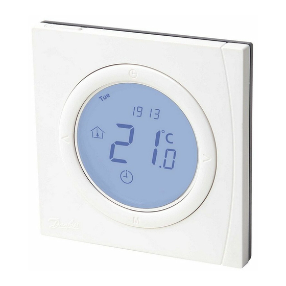
- Page 1 Installation Guide BasicPlus WT-D & WT-P Room Thermostats...
-
Page 2: Installation Steps
2. Wiring Dimensions, see fig. 4. Wiring diagram, see fig. 5 (S1, S2: floor sensor terminals). WT-D/P is often used with Danfoss TWA actuator. Depending on the conditions of power location and actuator type (NC or NO), the wiring between room thermostat and actuator is different. -
Page 3: Error Codes
4. If walls must be painted, mount the room thermostat after painting, to avoid dust or paint material pen- etrating the room thermostat and thus damaging the PCB. Danfoss Heating Solutions VICUJ212... -
Page 4: Technical Specifications
<1 A Max. load, resistive <3 A Power consumption Power supply 85-250 Vac, 50/60 Hz Room temp. set range 5 - 35° C Floor temp. set range 20 - 45° C Shell material ABS + PC VICUJ212 Danfoss Heating Solutions... - Page 5 Installation Guide BasicPlus WT-D & WT-P Fig. 1 Fig. 2 Fig. 3 Danfoss Heating Solutions VICUJ212...
- Page 6 Installation Guide BasicPlus WT-D & WT-P Fig. 4 86.0 16.0 24.5 50.0 Fig. 5 230 V ~ Fig. 6 WT-D/P 230V L NO NC N S1 S2 230 V ~ VICUJ212 Danfoss Heating Solutions...
- Page 7 Fig. 7 WT-D/P 230V NO NC N S1 S2 230 V ~ Fig. 8 WT-D/P 230V L NO NC N S1 S2 230 V ~ Fig. 9 WT-D/P 230V NO NC N S1 S2 230 V ~ Danfoss Heating Solutions VICUJ212...
- Page 8 Danfoss can accept no responsibility for possible errors in catalogues, brochures and other printed material. Danfoss reserves the right to alter its products without notice. This also applies to products already on order provided that such alterations can be made without subsequential changes being necessary in specifications already agreed.