Fluke 8508A User Manual
Reference multimeter
Hide thumbs
Also See for 8508A:
- User manual (196 pages) ,
- Service manual (120 pages) ,
- Extended specifications (17 pages)
Table of Contents
Advertisement
Quick Links
Advertisement
Table of Contents

Related Manuals for Fluke 8508A


Summary of Contents for Fluke 8508A
- Page 1 8508A Reference Multimeter Users Manual PN 1673798 July 2002 Rev. 6, 3/13 © 2002-2013 Fluke Corporation, All rights reserved. Printed in UK. Specifications are subject to change without notice. All product names are trademarks of their respective companies.
- Page 2 Fluke authorized resellers shall extend this warranty on new and unused products to end-user customers only but have no authority to extend a greater or different warranty on behalf of Fluke. Warranty support is available only if product is purchased through a Fluke authorized sales outlet or Buyer has paid the applicable international price.
-
Page 3: Table Of Contents
Table of Contents Chapter Title Page Introduction and Safety Information ..........1-1 Introduction......................1-3 How to Contact Fluke ..................1-3 Unpacking and Inspection.................. 1-4 Standard Accessories..................1-4 Optional Accessories ..................1-5 Storing and Shipping the Multimeter ..............1-6 Line Voltage ...................... 1-6 Power Voltage Selector and Fuses .............. - Page 4 Rear Inputs..................... 2-8 External Trigger Input ................... 2-8 IEEE 488 Input/Output.................. 2-8 Power-On Configuration ..................2-8 The 8508A-LEAD Measurement Lead Kit ............2-9 Making Measurements ................ 3-1 Introduction......................3-3 Making Connections to the Multimeter -- General Guidelines ......3-4 Using the Measurement Functions..............3-5 DC Voltage....................
- Page 5 The Multimeter in IEEE 488.2 Terminology ..........4-3 Programming Options ................... 4-3 Capability Codes ................... 4-3 Interconnections....................4-4 Using the 8508A Reference Multimeter in a System ........4-5 Setting the Multimeter Address ..............4-5 Remote Operation General Considerations ........... 4-5 Syntax Diagrams in this Manual ..............4-5 The 8508A Status Reporting Structure............
- Page 6 8508A Users Manual Selftest ......................4-31 Device Errors and Syntax Diagrams ..............4-31 Error Detection ....................4-31 Recall Device Errors ..................4-32 Triggering and Reading Operations ..............4-33 Trigger Source Selector ................. 4-33 Execute Trigger ..................... 4-34 Execute Trigger and Take a Reading ............4-34 Settling Delay ....................
- Page 7 (continued) Contents Accessing the Calibration Menus and Calibration Mode ......6-4 Calibration Menu................... 6-5 SET VALUE Menu ..................6-5 SPOT CAL Menu ..................6-6 SPOT (1 to 6) RMS Menus ................6-6 SPOT FREQUENCY (1 to 6) Menu ............. 6-7 Special Calibration ..................
- Page 8 8508A Users Manual...
- Page 9 List of Tables Table Title Page 1-1. Standard Accessories ..................... 1-4 1-2. Additional Accessories for the Multimeter ............1-5 1-3. Power Input Fuse 1 ....................1-12 1-4. Current Function Rear Input Fuse 2 ............... 1-12 3-1. Identifying and Avoiding Errors ................3-4 3-1.
- Page 10 8508A Users Manual viii...
- Page 11 Front and Rear Input Terminals ................2-3 2-3. Sample of the Main Display ................... 2-4 2-4. 8508A Rear Panel Detail..................2-7 2-5. The 8508A-LEAD Measurement Lead Kit ............2-10 3-1. Simple Lead Connections ..................3-7 3-2. Twisted-Pair Cable Connections ................3-7 3-3.
- Page 12 8508A Users Manual...
-
Page 13: Introduction And Safety Information
Chapter 1 Introduction and Safety Information Title Page Introduction......................1-3 How to Contact Fluke ..................1-3 Unpacking and Inspection.................. 1-4 Standard Accessories..................1-4 Optional Accessories ..................1-5 Storing and Shipping the Multimeter ..............1-6 Line Voltage ...................... 1-6 Power Voltage Selector and Fuses ..............1-6 Changing Supply Voltage or Replacing Line Fuse ........ - Page 14 8508A Users Manual 1-2...
-
Page 15: Introduction
Introduction and Safety Information Introduction Introduction The Fluke 8508A Reference Multimeter (hereafter "the Multimeter") is designed for the most demanding measurement applications and provides extremely high measurement precision in both stand-alone and systems applications. Chapter 1 ‘Introduction and Safety Information’ provides unpacking, storage and shipping instructions, line voltage, and safety information. -
Page 16: Unpacking And Inspection
If damage is found notify the carrier and your sales representative immediately. For orders of the model 8508A/01 check that the instrument has the six terminals on the rear panel for connection of signals. Standard Accessories The standard accessories supplied with the instrument are shown in Table 1-1. -
Page 17: Optional Accessories
4x Shielded leads with gold spades 1x High-current lead with gold spades 1x General Purpose Probe Kit (as above) Please note that accessories (except for Accredited Calibration) are generally shipped separately, please refer to the Packing List supplied with your 8508A. -
Page 18: Storing And Shipping The Multimeter
Power Voltage Selector and Fuses The instrument is packed ready for use with a line voltage determined at the time of ordering. 8508A 115 or 8508A/01 115 For 100V to 120V supplies 8508A 240 or 8508A/01 240 For 200V to 240V supplies... -
Page 19: Calibration Enable Switch
Introduction and Safety Information Calibration Enable Switch Calibration Enable Switch This two-position switch on the rear panel protects the instrument calibration memory. The instrument was initially calibrated at the factory and the switch covered with a calibration sticker, so the sticker and the switch should remain as delivered, until immediate recalibration is intended. -
Page 20: Safety Information
8508A Users Manual Safety Information A Warning identifies conditions and procedures that are dangerous to the user. Warning To prevent possible electrical shock, fire, or personal injury: • Read all safety information before you use the Product. • Carefully read all instructions. - Page 21 Introduction and Safety Information Safety Information • Disconnect the mains power cord before you remove the Product covers. • Remove the input signals before you clean the Product. • Use only specified replacement parts. • Use only specified replacement fuses. •...
-
Page 22: Symbols
Directive Annex I, this product is classed as category 9 "Monitoring and Control Instrumentation” product. Do not dispose of this product as unsorted municipal waste. Go to Fluke’s website for recycling information. Product conforms with the requirements of the applicable EC directives. -
Page 23: Protection Class I
Introduction and Safety Information Symbols Protection Class I Protective Earth/Ground The Multimeter must be operated with a Protective Earth/Ground connected via the power cable's protective earth/ground conductor. The Protective Earth/Ground connects to the instrument before the line & neutral connections when the supply plug is inserted into the power socket on the back of the instrument. -
Page 24: Fuse Requirements
5HT 1.25-R Table 1-4. Current Function Rear Input Fuse 2 - F 1.6AH 250V Fuse Rating Manufacturer Fuse Action Fluke Part No. IEC 127 (UL / CSA) & Type No. Bussman S501-1.6-R Littelfuse 021601.6HXP 1.6 A (2 A)@ 250 V... -
Page 25: Terminal Connections
Introduction and Safety Information Symbols Terminal Connections Make sure that the instrument is correctly grounded (earth ground) via the power cable before and while any other connection is made. Measurement Category I Measurement and/or guard terminals are designed for connection at Measurement Category I. - Page 26 8508A Users Manual 1-14...
-
Page 27: Getting Acquainted With The Basics
Power Input and Power Switch ............... 2-7 Calibration Switch ................... 2-7 Rear Panel Connectors and Pin Designations ............2-8 Rear Inputs....................... 2-8 External Trigger Input ..................2-8 IEEE 488 Input/Output..................2-8 Power-On Configuration..................2-8 The 8508A-LEAD Measurement Lead Kit ............2-9... - Page 28 8508A Users Manual 2-2...
-
Page 29: Introduction
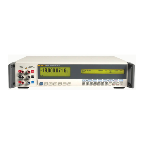
Getting Acquainted with the Basics Introduction Introduction Chapter 2 introduces the front and rear panel features of the 8508A Reference Multimeter (hereafter, referred to as the Multimeter). Figure 2-1 shows the Multimeter's front panel controls, indicators, and connectors. adj002f.eps Figure 2-1. Front Panel Displays Input Terminals ... -
Page 30: The Front Panel Displays
8508A Users Manual The Front Panel Displays The front panel (Figure 2-1) has two displays: • The display on the left, the main display, is used to show all measurement readings, with status legends on the bottom line, and measurement qualifiers on the line above. -
Page 31: Numeric Keyboard
Getting Acquainted with the Basics Front Panel Keys Helvetica-underline In this manual, a Choice soft-key is shown as displayed or in font Example: 100mV Numeric Keyboard adj012f.eps Numeric Keyboard The operation of the numeric keys is enabled for appropriate menus. The active keys are: ... -
Page 32: Direct Action Keys
8508A Users Manual Direct Action Keys adj017f.eps Direct Action Keys Press to disable internal triggers and enable all external trigger sources. The annunciator on the main display is lit. An external trigger for a measurement may be generated either by pressing the... -
Page 33: Rear Panel
IEC127 MADE IN UK CERTIFIED TO CAN/CSA STD. C22.2 No.61010.1-04 AUX EARTH (GROUND) adj018f.eps Figure 2-4. 8508A Rear Panel Detail Labels Attached to the rear panel is the identification label for the instrument, and a modification strike label. Fuses Located in the fuse drawer which is part of the integrated module for Power Fuse: ... -
Page 34: Rear Panel Connectors And Pin Designations
8508A Users Manual Rear Panel Connectors and Pin Designations Warning This instrument can deliver a lethal electric shock. To avoid electric shock, personal injury, or death, never touch any lead or terminal unless you are absolutely certain that no dangerous voltage is present. -
Page 35: The 8508A-Lead Measurement Lead Kit
A General Purpose Probe Kit is provided with the Multimeter. Instructions for use are included. The optional 8508A-LEAD Measurement Lead Kit is a comprehensive set of high integrity measurement leads, designed for metrology applications. The kit and its contents are described below and shown in figure 2-5. The kit includes the following: 1. Five low-thermal-EMF low-leakage leads sets for low voltage precision measurement... - Page 36 8508A Users Manual Four low thermal, PTFE insulated and shielded leads for signal applications. One heavy gauge lead for high current (>2 A rms) applications. General Purpose Probe Kit and Wallet. adj388f.eps Figure 2-5. The 8508A-LEAD Measurement Lead Kit 2-10...
-
Page 37: Making Measurements
Chapter 3 Making Measurements Title Page Introduction......................3-3 Making Connections to the Multimeter -- General Guidelines ......3-4 Using the Measurement Functions............... 3-5 DC Voltage...................... 3-5 Measuring DC Voltage..................3-7 Making Input Connections................3-7 AC Voltage...................... 3-8 Measuring AC Voltage..................3-11 Induced Interference .................. - Page 38 8508A Users Manual Displaying Maximum, Minimum, and Peak-to-Peak Readings ...... 3-33 MAX Menu ....................3-33 Limit-Checking ................... 3-33 Monitor Menu Tree ..................3-34 Utility ........................3-34 Using the Selftest Functions ................3-37 Test Menu Tree....................3-38 Test Key ......................3-39 Using the Math Functions..................
-
Page 39: Introduction
Multimeter or equipment to which it is connected. Chapter 3 explains in detail how to use the 8508A Reference Multimeter's (hereafter “the Multimeter”) measurement functions and operating modes. It is organized to provide easy access to the following functions and modes. -
Page 40: Making Connections To The Multimeter -- General Guidelines
Users Manual Making Connections to the Multimeter -- General Guidelines The 8508A Reference Multimeter is capable of providing highly accurate traceable measurements. To attain this accuracy, it is necessary to make connections to any external circuitry or load correctly. A few guidelines are given in Table 3-1. -
Page 41: Using The Measurement Functions
Making Measurements Using the Measurement Functions Using the Measurement Functions If you are unfamiliar with the front panel controls, review the relevant sections of Chapter 2. DC Voltage Press display the menu. DCV key to adj055f.eps DCV Menu This function provides both 2-wire and 4-wire measurements, in decade ... - Page 42 8508A Users Manual DCV Resolution Press the key to see the menu: Resl DCV RESL adj058f.eps DCV Resolution Menu 5-1/2-digits resolution 6-1/2-digits resolution 7-1/2-digits resolution 8-1/2-digits resolution To revert to the menu, press the key. DCV CONFIG CONFIG To revert to the...
-
Page 43: Measuring Dc Voltage
Making Measurements Using the Measurement Functions Measuring DC Voltage Making Input Connections Simple Lead Connection For the majority of applications the simple lead connection without external guard will be adequate. See Figure 3-1.The disadvantage of this simple arrangement is that the connecting leads can form a loop. -
Page 44: Ac Voltage
8508A Users Manual Internal Guard Connections not selected: The Guard terminals on the front and rear panels are External Guard isolated from each other and from any internal connection. The internal guard shields and tracks are connected directly to the internal 0V. - Page 45 Making Measurements Using the Measurement Functions ACV Configuration (4 wire Sense, Resolution, RMS Filtering, Transfer mode, DC- Coupled and Spot Frequency) Press the key to see the menu. Config ACV CONFIG adj067f.eps ACV CONFIG Menu Allows operation with calibrators which provide a remote 4 wire sensing ...
- Page 46 8508A Users Manual ACV Resolution Press the key to see the menu: Resl ACV RESL adj068f.eps ACV RESL Menu 5-1/2-digits resolution 6-1/2-digits resolution To revert to the menu, press the key. ACV CONFIG Config ACV Filter Press the key to see the...
-
Page 47: Measuring Ac Voltage
Users should take care to avoid measurement errors from the interaction of lead capacitance and inductance with any source output impedance. Additional information and guidance is available in the Fluke publication Calibration: Philosophy in Practice (ISBN 0-9638650-0-5). Resistance Press Ω... - Page 48 8508A Users Manual OHMS Configuration (Resolution, Filter, Fast, Low Current and 4-Wire Operation) Press the key to see the menu. Config OHMS CONFIG adj074f.eps OHM CONFIG Menu Provides selection of the resolution for subsequent readings. Controls a single-pole analog filter for increased noise rejection.
-
Page 49: High Voltage Ohms
Making Measurements Using the Measurement Functions OHMS Resolution Press the key to see the menu: Resl OHMS RESL adj075f.eps OHM RESL Menu 5-1/2-digits resolution 6-1/2-digits resolution 7-1/2-digits resolution 8-1/2-digits resolution Refer to Table 3-2 for the ADC integration times applicable to the various resolution and Fast On/Off settings. - Page 50 8508A Users Manual The MAXIMUM voltage that could appear across the measured resistor is 240 V. No autoranging is provided in this function. Warning DANGER OF LETHAL ELECTRIC SHOCK To avoid LETHAL electrical shock DO NOT CONNECT EXTERNAL CAPACITANCE greater than 50 nF to the Multimeter terminals.
-
Page 51: True Ohms
Making Measurements Using the Measurement Functions Resolution HIVΩ Press the key to see the menu: Resl HIΩ RESL adj080f.eps HiVΩ RESL Menu 5-1/2-digits resolution 6-1/2-digits resolution 7-1/2-digits resolution 8-1/2-digits resolution Refer to Table 3-2 for the ADC integration times applicable to the various resolution and Fast On/Off settings. - Page 52 8508A Users Manual resistance from the instrument's terminals and the INPUT Hi resulting potential difference is sensed by the terminals SENSE Hi To cancel autoranging and enter a manually selected range, press any range selection or the Auto softkey. The Multimeter enters the selected range or reverts to the auto-selected range.
-
Page 53: Measuring Resistance
Making Measurements Using the Measurement Functions Ω - Movement between Menus adj086f.eps Ω Movement Between Menu Measuring Resistance 2-Wire Measurements For many applications the simple 2-wire arrangement will be adequate. See Figure 3-5. However, the value displayed will include the resistance of the connecting leads. Use a shielded twisted-pair cable, preferably of PTFE insulation, to reduce induced voltages, induced charge and shunt leakage resistance, particularly where Rx is high. -
Page 54: 4-Wire High Resistance Measurements
LEAD leadkit. Fitted over the Input Hi, Input Lo, Sense Hi and Sense Lo terminals these provide a convenient means of zeroing the 8508A inputs at the terminals. Use of the 4-wire short device at the multimeter terminals does not address potential sources of error within measurement cables. -
Page 55: Ω Guard
Making Measurements Using the Measurement Functions INPUT HI Metal Screen SENSE HI INPUT HI SENSE HI INPUT LO GUARD GUARD SENSE LO SENSE LO INPUT LO adj094f.eps Figure 3-8. 4-Wire Resistance Zero Measurements Ω Guard In the resistance function with Ext Grd selected the Guard terminal functions as terminal as Guard, the Guard feature can be used to make... - Page 56 8508A Users Manual INPUT HI Metal Screen SENSE HI SENSE HI INPUT HI GUARD GUARD SENSE LO INPUT LO SENSE LO INPUT LO adj095f.eps Figure 3-9. Ω Guard Measurements Internal Guard Connections not selected: In the Ohms or PRT Functions the Guard terminals on the External Guard front and rear panels are isolated from each other and from any internal connection.
-
Page 57: Dc Current
Making Measurements Using the Measurement Functions DC Current Press the key to show the menu. adj097f.eps DCI Menu This function provides measurements, in decade ranges from 200μA to 20A. (NOTE: the 20A range is only available on the front terminals. The front current terminal is not fused.) To cancel autoranging and enter a manually selected range, press any range ... -
Page 58: Measuring Dc Current
8508A Users Manual DC Current - Movement between Menus adj100f.eps Movement Between Menu Measuring DC Current Insert the Multimeter in the current path via its terminals, so that INPUT A INPUT Lo conventional current flows from the source Hi into the Multimeter's... -
Page 59: Ac Current
Making Measurements Using the Measurement Functions AC Current Press the ACI key to show the ACI menu: adj101f.eps ACI Menu This function provides measurements, in decade ranges from 200μA to 20A. (NOTE: the 20A range is only available on the front terminals. The front current terminal is not fused.) To cancel autoranging and enter a manually selected range, press any range ... -
Page 60: Measuring Ac Current
Use shielded twisted pair cable to reduce induced interference signals, and connect Guard to the source of common mode voltage via the screen, to provide a separate common mode current path. The 8508A is designed to minimise the burden (compliance) voltage generated when making current measurements, thus improving measurement accuracy. -
Page 61: Temperature
The rear input A terminal is protected by a fuse mounted on the rear panel. Temperature The 8508A provides a temperature readout by measuring the resistance of the connected PRT or SPRT probe, and converting the resitance value to temperature. The multimeter autoranges between the 200 Ω... - Page 62 8508A Users Manual Provides selection of the temperature resolution for subsequent readings. This is the entry point to manage PRT probe information. PROBE Configuration Management (New, Edit, Delete) adj107f.eps PROBE CONFIG Menu The utilization and management of PRT probe data depends upon a probe identity. For example, before using the edit and delete capabilities a probe identity must be selected.
- Page 63 Making Measurements Using the Measurement Functions adj110f.eps Conversion Menu Select the conversion algorithm to be applied. This characteristic cannot be modified via . A measurement annunciator in the left-hand display indicates the Edit capability active conversion algorithm. This algorithm converts resistance to temperature according to the ITS-90 ...
-
Page 64: Measuring Temperature
8508A Users Manual The Rtp is the resistance of the probe at the triple point of water. For a probe calibrated for the subrange W7 the coefficient is equivalent to , coefficient is equivalent to , and . Similarly for a probe calibrated for the subrange W4 the coefficient... -
Page 65: Multimeter Inputs
Making Measurements Multimeter Inputs Multimeter Inputs Input key and its menu allow you to select either the Front or Rear panel terminals as Input the input to the Multimeter: The scan softkey gives access to dual-channel measurement and processing selection which produces a single result. Using the INPUT Key Press the key to see the... -
Page 66: Scan Operations
8508A Users Manual SCAN OPERATIONS adj128f.eps Scan Menu In each of three Scan modes, measurements are taken alternately from the Front and Rear Terminals and are combined mathematically to produce a single result as shown below. Readings are taken alternately from the front terminals and then the rear to ... -
Page 67: Tru Ohms Ratio
Making Measurements Multimeter Inputs Caution HIGH VOLTAGE To avoid equipment damage when using the HiVΩ function make sure that circuits or components connected to the Multimeter can withstand at least 240 V dc. Note Scan of Temperature Measurement - Scan Mode is not available in the PRT Function. -
Page 68: Monitoring Modes
8508A Users Manual Monitoring Modes Monitor Key Press the key to display menu: Monitor MONITOR adj116f.eps MONITOR menu Displaying Signal Frequency When measuring AC voltage or current, select the key to display the frequency Freq corresponding to the rms value shown on the main display. The response rate for the function frequency measurements can be set in the menu. -
Page 69: Displaying Maximum, Minimum, And Peak-To-Peak Readings
Making Measurements Monitoring Modes Displaying Maximum, Minimum, and Peak-to-Peak Readings , and menus have the same format and show information derived PKPK from measurements taken since the , or mode was reset. Pkpk Once one of the three menus has been entered, you can select either of the other two without going through the menu. -
Page 70: Monitor Menu Tree
8508A Users Manual Monitor Menu Tree An overview of the mode and a diagram of the menu tree follows. Monitor Monitor ON/OFF adj114f.eps Monitor Menu Tree Note From any of these menus, pressing the hard key will enter the Config menu;... - Page 71 Making Measurements Utility Provides a contrast menu for adjustment to the right hand display. Provides selection of the power line frequency for the Multimeter. When in ACV function this softkey displays the menu to view the SPOTF ...
- Page 72 8508A Users Manual SER# Display adj123f.eps Ser# display This display is for information only. The serial number cannot be altered except in one of the calibration menus at the factory. The software issue number (last four digits) is embedded in the software itself, and is not user-alterable.
-
Page 73: Using The Selftest Functions
Making Measurements Using the Selftest Functions Status Reporting - Movement between Menus adj124.eps Status Reporting -- Movement Between Menus Using the Selftest Functions This section covers the Multimeter's selftest functions that can be performed via the Test key. An overview of the mode and a diagram of the menu tree is provided in Test... -
Page 74: Test Menu Tree
8508A Users Manual Test Menu Tree adj125.eps Test Menu Tree 3-38... -
Page 75: Test Key
Making Measurements Using the Selftest Functions Test Key Press the key to display the menu, from which you can choose to perform a Test TEST variety of selftests. adj126f.eps TEST Menu menu allows you to initiate front panel display and key tests and ‘Circuit’ test. TEST Please note that the instrument should be allowed a warm up period of 10 minutes before performing an internal self test and that ambient temperature should be between 15... -
Page 76: Using The Math Functions
8508A Users Manual Using the Math Functions Math Functions and Menu Tree adj127f.eps Math Menu Tree Press the key to display the menu. The MATH menu provides selections for Math MATH a variety of linear, averaging, and logarithmic calculations. adj129f.eps... -
Page 77: Math Configuration
Making Measurements Using the Math Functions Note From any of the menus below, pressing the key enters the Config MATH menu; pressing the key reverts to the menu. CONFIG Math MATH Press to revert automatically to the menu. Enter Quit MATH CONFIG Causes a rolling average of R readings to be made. -
Page 78: Clear Functions
8508A Users Manual Clear Functions adj143f.eps CLEAR Menu The ‘input zero’ corrections will remain active until power down, but the selections available in this menu will allow the corrections to be cleared. Removes the correction for the currently selected range and function. -
Page 79: Remote Operations Using The Ieee 488 Interface
The Multimeter in IEEE 488.2 Terminology ..........4-3 Programming Options ..................4-3 Capability Codes ..................... 4-3 Interconnections....................4-4 Using the 8508A Reference Multimeter in a System .......... 4-5 Setting the Multimeter Address ............... 4-5 Remote Operation General Considerations ............. 4-5 Syntax Diagrams in this Manual ..............4-5 The 8508A Status Reporting Structure............ - Page 80 8508A Users Manual Subtraction....................... 4-28 Division ......................4-29 Decibel Calculations..................4-30 Syntax Diagram of Test ..................4-31 Selftest ......................4-31 Device Errors and Syntax Diagrams ..............4-31 Error Detection ....................4-31 Recall Device Errors ..................4-32 Triggering and Reading Operations ..............4-33 Trigger Source Selector ...................
-
Page 81: Introduction
Introduction Chapter 4 provides the information necessary to operate the 8508A Reference Multimeter remotely via the IEEE 488 Interface. (Hereafter, the 8508A is also referred to as "the Multimeter" or, in the context of IEEE 488.2 terminology, "the device") For users unfamiliar with the IEEE 488 Interface, refer to the standard specification, which appears in the publications ANSI/IEEE Std. -
Page 82: Interconnections
Gnd wire of NDAC twisted pair GND 9 Gnd wire of IFC twisted pair GND 10 Gnd wire of SRQ twisted pair GND 11 Gnd wire of ATN twisted pair 8508A Logic Ground (internally connected to 8508A Safety Ground) Figure 4-1. IEEE 488 Input/Output Connector... -
Page 83: Using The 8508A Reference Multimeter In A System
Remote Operation General Considerations When the 8508A Reference Multimeter is operating under the direction of the controller, the right hand display indicates Remote Operation together with the function and range settings. The front panel controls are disabled with the exception of LOCAL (provided Local Lockout has not been programmed). - Page 84 The Program Message Terminator The message terminator for the 8508A Reference Multimeter is the hexadecimal number 0A , characterized in IEEE 488.2 as NL. Alternatively, the EOI (end or identify) line can be set true with the last byte to be sent.
- Page 85 Remote Operations Using the IEEE 488 Interface Using the 8508A Reference Multimeter in a System Program Header Data Element adj201f.eps Program Header Separator - phs The Program Header The ‘Program Header’ provides the main command identification. This may be followed by ‘Program Data Elements’...
-
Page 86: The 8508A Status Reporting Structure
Query Error Operation Complete MESE phs Nrf Measurement Event Status Enable Register MESE? Measurement Event Status MESR? Register Reading Available Number of Stored Readings Matches Commanded BlockSize Mathematical Overflow Overload Lo Limit Hi Limit adj208f.eps Figure 4-2. 8508A Status Report Structure... -
Page 87: Types Of Status Information Available
• The Measurement Event Status Register, and its associated enable register, control the generation of the Measurement Event Status Byte, whose component bits relate to measurement events in the 8508A. It is summarized by the MES bit 0 in the Status Byte. -
Page 88: Syntax Diagrams Of Major 8508A Functions
• Request Control - provided for devices which are able to assume the role of controller. This capability is not available in the 8508A. • Operation Complete - initiated by a message from the controller, indicates that the 8508A has completed all selected pending operations. -
Page 89: Ac Voltage
Remote Operations Using the IEEE 488 Interface Syntax Diagrams of Major 8508A Functions A numeric value that selects the range for the expected signal. For example, an of 2, 10, or even 15.6789, selects the 20 V range. Any valid numeric value cancels autorange. - Page 90 8508A Users Manual A numeric value that selects the range for the expected signal. For example, an of 2, 10, or even 15.6789, selects the 20 V range. Any valid numeric value cancels autorange. AUTO Selects the autorange mode where the multimeter will determine the appropriate range for the measured signal.
-
Page 91: Resistance: Normal Ohms
Remote Operations Using the IEEE 488 Interface Syntax Diagrams of Major 8508A Functions Recall of Spot Frequency Value SPOT? adj211f.eps Recall of Spot Frequency (Nr3) Recalls the frequency value for the specified calibrated spot on the active ACV range. Resistance: Normal OHMS... -
Page 92: Resistance: High Voltage Ohms
8508A Users Manual RESL5 / RESL6 / RESL7 / RESL8 Sets the resolution of the measurement to 5.5, 6.5, 7.5, or 8.5, digits. FAST_ON / FAST_OFF Reduces the A-D integration time, for faster conversions. FAST_ON TWO_WR Selects 2-wire Ohms (Use Hi and Lo terminals). (For backwards compatibility TWR can also be used.) -
Page 93: Resistance: True Ohms
Remote Operations Using the IEEE 488 Interface Syntax Diagrams of Major 8508A Functions TWO_WR Selects 2-wire Ohms (Use Hi and Lo terminals). (For backwards compatibility TWR can also be used.) FOUR_WR Selects 4-wire Ohms. (For backwards compatibility FWR can also be used.) Power On and Reset Conditions 20 MΩ, FILT_OFF, RESL6, FAST_OFF, TWO_WR... -
Page 94: Dc Current
8508A Users Manual DC Current The following commands are used to select the function and set its configuration. A UTO FILT_ON FILT_OFF RESL5 RESL6 RESL7 FA ST_ON FA ST_OFF adj215f.eps DC Current A numeric value that selects the range for the expected signal. Any valid numeric value cancels autorange. -
Page 95: Ac Current
Remote Operations Using the IEEE 488 Interface Syntax Diagrams of Major 8508A Functions AC Current The following commands are used to select the function and set its configuration. A CI A UTO FILT100HZ FILT40HZ FILT10HZ FILT1HZ RESL5 RESL6 DCCP A CCP adj216f.eps... -
Page 96: Using Platinum Resistance Thermometers To Obtain Temperature
8508A Users Manual Using Platinum Resistance Thermometers to obtain Temperature. The following commands are used to select the function and set its configuration. identity DEG_K DEG_C DEG_F RESL5 RESL6 RESL7 RESL8 adj356f.eps Platinum Resistance Thermometers Identity This is a string value and thus must be enclosed in double quotes and must be identical in all respects with the identity of an already entered PRT. -
Page 97: Entering Or Editing The Characteristics Of A Prt To Non-Volatile Store
Remote Operations Using the IEEE 488 Interface Syntax Diagrams of Major 8508A Functions Entering or Editing the Characteristics of a PRT to Non-volatile Store The following commands are used to construct a identity and set associated parameters and coefficients. PRT_CHR... -
Page 98: Recalling The Characteristics Of A Known Prt
8508A Users Manual Execution Errors If the identity is unknown an error is generated for the coefficient entry. An error is generated if any of the coefficients exceed the limits for correct algorithm operation. Recalling the Characteristics of a Known PRT... -
Page 99: Input
Remote Operations Using the IEEE 488 Interface Syntax Diagrams of Major 8508A Functions Input The following commands are used to select an input; or combined usage of the two inputs to calculate the Ratio, Difference and Deviation measurement modes. The selections are mutually exclusive. -
Page 100: Measurement Gate Width
8508A Users Manual INT / EXT This selects the connection of the multimeter’s guarding. (For backwards compatibility LCL & REM can also be used.) For scan operations, the guard selection is applied to the channel currently being applied to the A-D converter. - Page 101 Remote Operations Using the IEEE 488 Interface Syntax Diagrams of Major 8508A Functions PKPK? Obtains the stored value representing the difference between the maximum and minimum signal values to be measured since the most-recent general reset, store reset or function change.
-
Page 102: Limits
8508A Users Manual Limits Each command sets its corresponding limit, for comparison with each measurement when enabled. HILT LOLT adj223f.eps Setting Hi/Lo Limits A Decimal Numeric Data element that represents the mathematical value to be used for limit-checking. Its resolution is 8.5 significant digits; numbers in excess of this resolution will be rounded to it. -
Page 103: Standard Deviation
Remote Operations Using the IEEE 488 Interface Syntax Diagrams of Math Functions Standard Deviation Each of these queries recalls the stored standard deviations for a block of readings. DEVTN? READING DEVTN? ABSOLUTE adj363f.eps Recall Standard Deviation DEVTN? READING (Nr3) Recalls the standard deviation of the block relative to the mean of the block. DEVTN? ABSOLUTE (Nr3) Recalls the standard deviation of the block as an absolute quantity. - Page 104 8508A Users Manual Enable Averaging All selections are mutually exclusive. AV16 AV64 BLOC_N adj226f.eps Enable Averaging AVG AV... Averages the number of readings requested (4, 16, or 64) as a rolling average. Note From a cleared average memory, the average is the mean of the number of readings to date, until the selection window number is reached.
-
Page 105: Multiplication
Remote Operations Using the IEEE 488 Interface Syntax Diagrams of Math Functions Recall Block Size adj228f.eps Recall block Size (Nr1) Recalls the active value of "N". Multiplication Each signal value is multiplied by a user-defined factor "M". Enable Multiplication Selects the multiplication operation to be performed on the measurement. MUL_M adj229f.eps Enable Multiplication... -
Page 106: Subtraction
8508A Users Manual Recall Multiplication Constant adj231f.eps Recall Multiplication Constant ( Nr3) Recalls the defined value of M. Subtraction A user-defined constant "C" is subtracted from each signal value. Enable Subtraction Selects the subtraction operation to be performed on the measurement. -
Page 107: Division
Remote Operations Using the IEEE 488 Interface Syntax Diagrams of Math Functions Recall Subtraction Constant adj234f.eps Recall Subtraction Constant (Nr3) Recalls the defined value of C. Division Each signal value is divided by a user-defined factor "Z". Enable Division Selects the division operation to be performed on the measurement. DIV _Z adj235f.eps Enable Division... -
Page 108: Decibel Calculations
8508A Users Manual Recall Division Constant adj237f.eps Recall Division Constant (Nr3) Recalls the defined value of z. Decibel Calculations Decibel operations calculate, and express in decibels, the ratio of the reading to one of four standard references: unity, and 1 mW in either 50 Ω, 75 Ω or 600 Ω. As the dB calculation is set as the final part of any calculation, it is also possible to use the other Math operations to alter the effective reference value. -
Page 109: Syntax Diagram Of Test
Remote Operations Using the IEEE 488 Interface Syntax Diagram of Test Recall dB Reference Value DB_REF? adj240f.eps Recall dB Reference Value DB_REF? (Nr3) Recalls the current value of the DB_REF voltage. The value returned is the voltage value assigned to the program data elements: The element UNITY: +1.00000000E+00. -
Page 110: Recall Device Errors
8508A Users Manual A device-dependent error (DDE) is generated if the device detects an internal operating fault (e.g., during self-test). The DDE bit (3) is set true in the Standard-defined Event Status Byte, and the error code number is appended to the Device-Dependent Error queue. -
Page 111: Triggering And Reading Operations
Remote Operations Using the IEEE 488 Interface Triggering and Reading Operations EXQ? Recalls the last error from the queue of execution errors. An execution error occurs when a command cannot be complied with. Read the Queue until Empty. It is good practice to read the queue until empty on each occurrence of execution error, to prevent unrelated history of errors being retained. -
Page 112: Execute Trigger
8508A Users Manual Execute Trigger This command conforms to the IEEE 488.2 standard requirements. ∗ adj245f.eps Execute Trigger *TRG Equivalent to a Group Execute Trigger (GET). Causes a single reading to be taken. Execute Trigger and Take a Reading adj246f.eps... - Page 113 Remote Operations Using the IEEE 488 Interface Triggering and Reading Operations Delay Default Tables The delays listed in the following tables are active unless a specific delay is programmed. Once programmed, a specific delay will be applied to all subsequent readings providing External Trigger mode is selected until either the DELAY DFLT command is received, or the instrument is returned to local control.
-
Page 114: Input Zero
8508A Users Manual Input Zero Determines and corrects for the input zero and stores the result in volatile memory. An Input Zero is stored only for the input channel selected. Each input has its own set of Input Zero stores, for all of the applicable range/function combinations. For OHMS function an independent Input Zero should be executed for the two/four wire connection and for the low/normal current selection. -
Page 115: Access To The Internal Buffer Memory
Remote Operations Using the IEEE 488 Interface Triggering and Reading Operations If no trigger has been received to generate a conversion of the input signal, then the response to this command will represent the most-recent measurement. If a trigger has already been received, this query will wait for the completion of the measurement before placing the result in the output queue. - Page 116 8508A Users Manual At the completion of the block of measurements, bit 0 of the 8508A Status Byte is set, providing the appropriate bits of the Service Request Enable register (bit 0) and Measurement Event Status Enable register (bit 6) are set. Use of commands associated with this internal store prior to the completion of the specified number of readings, will abort the diversion of results.
-
Page 117: Internal Operations Commands
Remote Operations Using the IEEE 488 Interface Internal Operations Commands Example: BLOCK 16 Locations of readings stored by 3 4 5 10 11 12 13 14 15 16 17 18 19 20 22 BLOCK? 6,11 recalls selected readings consecutively from the stored block: First reading Last reading 8 9 10 11... -
Page 118: Complete Operations
8508A Users Manual Complete Operations *OPC A synchronization command that generates an operation complete message in the standard Event Status Register when all pending operations have been processed by the parser. ∗ adj253f.eps Complete OPC? A synchronization command that places the ASCII character ‘1’ in the output queue when all pending operations have been processed by the parser. - Page 119 Remote Operations Using the IEEE 488 Interface Status Reporting ∗ SRE phs Nrf Service Request Enable Register ∗ SRE? STATUS BYTE ∗ STB? REGISTER Request for Service Bit Master Status Summary Bit Event Status Summary Bit Message Available Bit Measurement Event Status Summary Bit Event ∗...
- Page 120 8508A Users Manual A number which, when rounded to an integer and expressed in base 2 (binary), enables the appropriate bits in this register. The detail definition is contained in the IEEE 488.2 document and in the status data structure diagram.
- Page 121 Remote Operations Using the IEEE 488 Interface Status Reporting ∗ESE? (Nr1) Recalls the enable mask for the standard defined event register. The returned value, when converted to base 2 (binary), identifies the bits as defined in the IEEE 488.2 standard and detailed in the status data structure diagram. Power On and Reset Conditions The Power ON condition depends on the condition stored by the common *PSC command - if 0 then it is not cleared;...
-
Page 122: Instrument I/D And Setup
8508A Users Manual Clear Status adj265f.eps Clear Status *CLS Clears all the event registers and queues except the output queue. The output queue and MAV bit will be cleared if *CLS immediately follows a '"Program Message Terminator". Power On Status Clear adj264f.eps... - Page 123 (String) Recalls the instrument’s option configuration which matches the options provided in the sales literature. Example: “8508A/01” -- for instrument fitted with rear terminals. Setting Line Frequency Selection of line frequency setting adjusts the integration time of the A-D converter for improved line frequency noise rejection.
-
Page 124: Calibration Commands And Messages
8508A Users Manual Calibration Commands and Messages Caution The descriptions in the following pages are intended only as a guide to the messages available to calibrate the instrument. They contain neither examples nor calibration routines, and should NOT be used directly as a basis for calibrating any part of the instrument. - Page 125 Remote Operations Using the IEEE 488 Interface Calibration Commands and Messages CAL? Triggers an external calibration event, including the "SET" feature used for local calibration. A numeric value representing the "SET" calibration value. This is used as the target for the actual measured value.
-
Page 126: Protected User Data
8508A Users Manual EXT_DUE? (String) Returns the user-entered recommended date for the re-calibration of the instrument. The date is that most-recently entered either as a parameter of EXITCAL, or when an exit was made from the front panel calibration mode. -
Page 127: Special Calibrations
Remote Operations Using the IEEE 488 Interface Calibration Commands and Messages Special Calibrations Perform a "Special" Calibration A DC CHSE? FREQ HV_LIN adj280f.eps Special Calibration CHSE? Triggers special calibration Aligns the different resolutions available from the analog to digital converter, so that there are no significant differences in readings when changing resolutions with a constant input value. - Page 128 8508A Users Manual SRC_N500 Measurement source is -500V DC. ZERO Measurement source is 0.0V DC. SRC_P500 Measurement source is +500V DC. SRC_P1K Measurement source is +1000V DC. Response (Nr1) The value returned identifies the success (0) or failure (1) of the measurement.
- Page 129 Remote Operations Using the IEEE 488 Interface Calibration Commands and Messages Exit from Calibration " " EXITCAL date string date string Exit from Calibration adj284f.eps EXITCAL Exits calibration mode giving the operator the option of entering a due date, or bypassing it as shown in the syntax diagram.
- Page 130 8508A Users Manual Clear Calibration Memory A LL CLRMEM HFTRIM adj289f.eps Clear Calibration Memory CLRMEM Clears the calibration correction memories. Caution This command can obliterate the results of an expensive original calibration or re calibration! The extent of clear is defined by programming the following options:...
-
Page 131: Specifications
Chapter 5 Specifications Title Page Specifications ..................... 5-3 General Specifications................... 5-3 Maximum Voltage and Current Inputs............5-4 DC and AC Voltage .................. 5-4 DC and AC Current................... 5-4 Resistance and Temperature ..............5-4 Electrical Measurement Specifications.............. 5-5 DC Current ....................5-6 AC Voltage.................... - Page 132 8508A Users Manual 5-2...
-
Page 133: Specifications
Specifications Specifications Specifications General Specifications Power Voltage designed for additional voltage fluctuations ±10 %. 115 V Setting ............. 100 V to 120 V rms designed for additional voltage fluctuations ±10 %. 230 V Setting ............. 200 V to 240 V rms ±3 Hz. -
Page 134: Maximum Voltage And Current Inputs
8508A Users Manual Maximum Voltage and Current Inputs Notes to maximum voltage and current input specifications • Maximum DC input equal to maximum rms input. Maximum peak input is rms x 1.414 • Specifications apply equally to front and rear input terminals except where noted below. -
Page 135: Electrical Measurement Specifications
Specifications Electrical Measurement Specifications Electrical Measurement Specifications Note Fluke guarantees 8508A performance verification using specifications stated to 99 % confidence level. DC Voltage [1] [2] [3] DC Voltage Uncertainty Relative to Cal Stds Absolute Uncertainties ± (ppm Reading + ppm Range) -
Page 136: Dc Current
8508A Users Manual DC Current [1] [2] [3] DC Current Uncertainty Relative to Cal Stds Absolute Uncertainties ± (ppm Reading + ppm Range) [15] Range Full Scale 24 hour 90 day 365 day 365 day 365 day TCal ±1 °C TCal ±1 °C... -
Page 137: Ac Voltage
Specifications Electrical Measurement Specifications AC Voltage [1] [2] [6] [7] [9] AC Voltage Uncertainty Relative to Cal Stds Absolute Uncertainties ± (ppm Reading + ppm Range) [15] Range Full Scale Frequency (Hz) 24 hour 90 day 365 day 365 day 365 day TCal ±1 °C TCal ±1 °C... - Page 138 8508A Users Manual [1] [2] [9] AC Voltage (Secondary Specifications) Temperature Coefficient 5 °C - 15 °C Range Frequency (Hz) 15 °C - 30 °C 30 °C - 40 °C ± ppm Reading/°C 1 - 10 10 - 40 40 - 100...
-
Page 139: Ac Current
Specifications Electrical Measurement Specifications AC Current [1] [2] [6] [9] AC Current Uncertainty Relative to Cal Stds Absolute Uncertainties Frequency ± (ppm Reading + ppm Range) [15] Range Full Scale (Hz) 24 hour 90 day 365 day 365 day 365 day TCal ±1 °C TCal ±1 °C TCal ±1 °C... - Page 140 8508A Users Manual [1] [2] [6] [9] AC Current (Secondary Specifications) Temperature Coefficient Input Impedance (Ω) 5 °C - 15 °C Range Frequency (Hz) 15 °C - 30 °C 30 °C - 40 °C ± ppm Reading/°C Range Front Rear 1 - 10 200 μA...
-
Page 141: Resistance
Specifications Electrical Measurement Specifications Resistance [1] [2] [3] Resistance Uncertainty Relative to Cal Stds Absolute Uncertainties ± (ppm Reading + ppm Range) [15] [10] Range Full Scale Mode 24 hour 90 day 365 day 365 day 365 day TCal ±1 °C TCal ±1 °C TCal ±1 °C TCal ±1 °C... - Page 142 8508A Users Manual [1] [2] [3] [10] Resistance - Normal Mode (Secondary Specifications) Transfer Temperature Coefficient Uncertainty 5 °C - 15 °C Measurement [16] 15 °C - 30 °C 5 °C - 40 °C Range 20 mins ±1 °C 30 °C - 40 °C Current ±...
-
Page 143: Temperature
Specifications Electrical Measurement Specifications Ratio Accuracy [17] Range to Range............Apply an RSS summation of Net Front Input and Rear Input Accuracy Within Range ............Using the 24 hour or 20 minute Transfer Uncertainty specifications as appropriate, apply an RSS summation of specified accuracy of the Front [17] Input signal and the specified accuracy of the Rear Input signal Settling Time ............ -
Page 144: Read Rate And Additional Uncertainty
8508A Users Manual Read Rate and Additional Uncertainty Read Rate and Additional Uncertainty [13] Read Rate Additional Errors Filter (readings/second) ± (ppm Reading + ppm Range) Function Resolution Frequency (Hz) Normal Fast Normal Fast 1/25 0 + 0 0 + 0.1 DCV, DCI &... -
Page 145: Applying The Specifications
Absolute specifications include the uncertainty of the standards used to perform calibration of the 8508A at manufacture and may be used to determine the uncertainty of measurements made with the 8508A for periods up to 1 year and over a temperature range of ±5 °C from calibration. -
Page 146: Applying User's Calibration Uncertainties
95 %. Check the applicable calibration uncertainties are stated at 95 % and then combine them with the 8508A 95 % Relative specifications. For example, if the 8508A is calibrated at 10 V DC with an uncertainty of 1.5 ppm at 95 %: The absolute uncertainty at 10 V for a period of 90 days... -
Page 147: Ratio Measurements
Applying the Specifications Ratio Measurements The 8508A Ratio mode will automatically take measurements of inputs applied to the front and rear terminals and display the result as a ratio in the voltage and resistance functions. The measurements can be made on the same range or different ranges. When... - Page 148 8508A Users Manual 5-18...
-
Page 149: Adjustment And Verification
Chapter 6 Adjustment and Verification Title Page Introduction......................6-3 Adjustment Overview ..................6-3 Adjustment Interval and Performance ..............6-3 Adjustment Points ....................6-3 Non-Nominal Values ..................6-4 Enabling Access to Calibration Adjustment Mode..........6-4 Calibration Menus....................6-4 Accessing the Calibration Menus and Calibration Mode ........ 6-4 Calibration Menu..................... - Page 150 8508A Users Manual DC Voltage Checks ..................6-37 AC Voltage Checks ..................6-40 Resistance Checks ................... 6-42 Normal Ω Checks .................... 6-44 Normal LoI Ω checks ..................6-44 Tru Ωchecks ....................6-44 Tru Ω LoI checks..................... 6-44 HiV Ω checks ....................6-44 DC Current Checks..................
-
Page 151: Introduction
Adjustment Interval and Performance It is recommended that the 8508A be adjusted on either a 365-day or 90-day interval depending on the requirements of the applications for which the 8508A is used and the performance specifications required. -
Page 152: Non-Nominal Values
In these cases, the use of the with a table of errors for the calibration source is recommended and will improve facility the accuracy of the 8508A adjustment. Enabling Access to Calibration Adjustment Mode Rear Panel Calibration Switch The setting of a Calibration-switch on the rear panel enables or restricts access to the Calibration mode. -
Page 153: Calibration Menu
(40 % on the 1000 V DCV and ACV ranges). The key has no effect until the SAMPLE Set value is stored by pressing the Enter key. The 8508A always chooses the most-recently stored Set value when adjusting. is not available for DCV, DCI, and Resistance range zero adjustments. -
Page 154: Spot Cal Menu
This menu is obtained by pressing the Set key in the CALIBRATION menu when the 8508A is in ACV Spot Frequency mode. It provides a means of adjusting the 8508A at any of six user-specific spot frequencies, at non-nominal adjustment values for each ACV range. -
Page 155: Spot Frequency (1 To 6) Menu
Adjustment and Verification Calibration Menus SPOT FREQUENCY (1 to 6) Menu Enter this menu by pressing in the menu, which also stores the Enter SPOT (1 to 6) RMS RMS value keyed in during this menu. The value in the SPOT FREQUENCY (1 to 6) menu is the measured frequency of the present adjustment input signal. -
Page 156: Ser# Menu
8508A Users Manual Selects the sequence required to correct the linearity of the 1kV DC range. Provides the capability to clear a section of the non-volatile memory for ‘test purposes only’. Permits entry of the instrument’s serial number. -
Page 157: Non-Volatile Input Offset Compensation
Non-volatile input offset compensation Good metrology practice should ensure that all high-precision measurements made with the 8508A are preceded by an input zero of each measurement. However, a non-volatile input-offset compensation is independently available for the front and rear inputs. This compensation is retained after power down and is unaffected by clearing the volatile input zeros. -
Page 158: Equipment Required For Adjustment
Availability of a 1 MHz frequency reference signal may be required for 5720A frequency locking during 8508A frequency adjustment procedure. Best uncertainties are obtained by characterizing the outputs of the 5720A and 5725A at the points used for 8508A adjustment. -
Page 159: Preparing For Adjustment
Adjustment and Verification Routine Adjustment Preparing for Adjustment The following procedures represent the recommended order of adjustment, giving all the necessary setup commands. 1. Allow the instrument to warm-up under power in the specified environment for at least 4 hours. 2. Press the key, select to restore the power up default configuration... -
Page 160: Interconnections
The Fluke 8508A-7000K Calibration kit contains a specially designed lead set which connects directly to the terminals of the 8508A, the 5720A, and the 5725A for the purpose of 8508A calibration. It is recommended that this lead kit be used to avoid introducing measurement errors due to interconnections and to duplicate the configuration used by Fluke for 8508A calibration. - Page 161 Adjustment and Verification Routine Adjustment Green Black White Blue Green White Link guard Black and ground terminal Blue CURRENT Link guard OUTPUT and ground terminal White CURRENT OUTPUT Green adj381f.eps Figure 6-1. Equipment Connections Required for Calibration 6-13...
-
Page 162: Adc Adjustment
No external equipment or signals are required to perform ADC adjustment. Procedure 1. Ensure that no signals are present on the 8508A inputs. The 8508A may be left connected to the calibrator as shown above provided the calibrator output is set to STANDBY. - Page 163 Set feature is not required, also omit steps 7 and 13 for the Range Gain Points. On each range, the 8508A automatically recognizes the appropriate value as range zero or range gain from the applied signal amplitude and polarity.
- Page 164 Range Gain to the minimum negative output (-1 digit) on that range. • For the 8508A 200V and 1kV DC ranges, setting the Calibrator to the Range Gain point will cause the Calibrator output to revert to Standby.
-
Page 165: Ac Voltage Adjustment
It is recommended that this resolution, Transfer On and 40Hz Filter is used for adjustment of all ACV ranges. 3. Confirm that the 8508A is configured for internal guard (External Guard is deselected) by checking that the legend does not appear on the left-hand ExGd display. - Page 166 4, 8, and 12. Adjusting the 1000V range at the recommended 500V requires a Set Value of 500 before the Zero cal. On each range, the 8508A automatically recognizes the appropriate value as range zero from the applied signal amplitude, and automatically recognizes the range LF and HF gain points from the applied signal frequency.
-
Page 167: Resistance Adjustment
A 1GΩ standard resistor provided in the 8508A-7000K Calibration kit is used for ranges above 200 MΩ as the highest resistance available from the 5720A calibrator is 100 MΩ. - Page 168 8508A Users Manual Table 6-5. Resistance Adjustment Points and Sequence 8508A Range Modes Point Resistance 2 Ω 0 Ω Normal, Normal LoI, Zero TruΩ, TruΩ LoI 1 Ω Range Gain 20 Ω 0 Ω Normal, Normal LoI, Zero TruΩ, TruΩ LoI Range Gain 10 Ω...
- Page 169 4WΩ 8508A when adjusting the 200 MΩ and 2 GΩ range, range zero, and range gain points. On each range, the 8508A automatically recognizes the appropriate value as range zero or range gain from the applied resistance value.
- Page 170 8508A 4WΩ when adjusting the 200 MΩ and 2 GΩ range, range zero, and range gain points. On each range, the 8508A automatically recognizes the appropriate value as range zero or range gain from the applied resistance value. Note It is unlikely that the resistance standard will be at exactly the nominal value required.
- Page 171 2 Ω range and work up to the 20 kΩ range. On each range, the 8508A automatically recognizes the appropriate value as range zero or range gain from the applied resistance value.
- Page 172 8508A Users Manual Range Zero and Gain Points 1. On the 8508A, press the Ω Plus key followed by the TruΩ to select the required range. 2. On the Calibrator select zero and to operate the output. Alternatively if using a standard resistor, connect the standard resistor for a 4 wire resistance zero.
- Page 173 Adjustment and Verification Routine Adjustment Range Zero and Gain Points 1. On the 8508A, press the Ω Plus key followed by the TruΩ to select the required range. 2. On the Calibrator select zero and to operate the output. Alternatively if using a standard resistor, connect the standard resistor for a 4 wire resistance zero.
- Page 174 8508A 4WΩ when adjusting the 200 MΩ and 2 GΩ range, range zero, and range gain points. On each range, the 8508A automatically recognizes the appropriate value as range zero or range gain from the applied resistance value. Note It is unlikely that the resistance standard will be at exactly the nominal value required.
- Page 175 For the 20MΩ range use 4 wire, for 200MΩ, 2GΩ and 20GΩ ranges use 2 wire mode on both the Calibrator and 8508A. 1. On the 8508A, press the Ω Plus key and select HiVΩ, select the required range. 2. On the Calibrator select zero and to operate the output.
- Page 176 DCI function. It is RESL7 recommended that this resolution is used for adjustment of all DCI ranges. 4. Confirm that the 8508A is configured for internal guard (External Guard is deselected) by checking that the legend does not appear on the left-hand ExGd display.
- Page 177 Set feature is not required, also omit steps 7 and 10 for the Range Gain Points. On each range, the 8508A automatically recognizes the appropriate value as range zero or range gain from the applied signal amplitude and polarity.
-
Page 178: Ac Current Adjustment
RMS filter is automatically selected. It is recommended that this resolution and 40Hz Filter is used for adjustment of all ACI ranges. 3. Confirm that the 8508A is configured for internal guard (External Guard is deselected) by checking that the... - Page 179 4 and 8. On each range, the 8508A automatically recognizes the appropriate value as range zero or range gain from the applied signal amplitude. 1. On the 8508A, select the required range.
-
Page 180: Frequency Adjustment
The 8508A frequency adjustment operation requires a signal at exactly 1MHz ( is not available on the 8508A for frequency adjustment). If the calibrator frequency output is not exactly nominal or sufficiently close to nominal it may be phase locked to an external reference frequency at the required output frequency applied to its rear panel phase lock input, for example from a laboratory frequency standard or off-air reference receiver. -
Page 181: Non-Volatile Input Offset Adjustment
4. Disconnect all leads and connect a 8508-7000K precision 4-wire short device to the front input terminals and also, if fitted, to the rear input terminals as shown above. 5. On 8508A select , and select CLEAR Pwr Up Dflt... -
Page 182: Acv Spot Frequency Adjustment
ACV Spot frequency adjustment is only performed if the user intends to make use of spot frequency mode. In spot frequency mode the accuracy of AC Voltage measurements can be improved by adjusting the 8508A at specific frequencies of interest, reducing frequency response flatness errors at these points. The following procedure provides guidance on spot frequency adjustment for users wishing to make use of Spot frequency mode. -
Page 183: Performance Verification
SPOT CAL 9. On the Calibrator, set STANDBY 10. On the 8508A, select other spots as required, repeating the process for each selection. Performance Verification The 8508A is a Digital Reference Multimeter offering state of the art performance. This procedure is intended as a guide for qualified metrology personnel who have access to a standards laboratory with equipment available to verify the performance of an instrument of this level of accuracy. -
Page 184: Equipment Requirements
8508A itself and the uncertainty of the calibration standards used to perform adjustment of the 8508A at the Fluke factory. They are applicable to a verification performed within a period of 365 days from adjustment and at a temperature within ±1°C of the temperature at which adjustment was performed (23°C for... -
Page 185: Preparation
Range Gain to the minimum negative output (-1 digit) on that range. • For the 8508A 200V and 1kV DC ranges, setting the Calibrator to the Range Gain point will cause the Calibrator output to revert to Standby. - Page 186 3. On the Calibrator, set zero output. Select to operate the calibrator output. 4. On the 8508A, press the Input key, and select Zero Rng to initiate the zeroing operation. The busy legend will appear, and then extinguish when the operation is complete.
- Page 187 Adjustment and Verification Performance Verification Table 6-8. DC Voltage Verification Points and Sequence 8508A Range Voltage Tolerance 200 mV 0 mV Perform input zero operation to calibrator range locked zero output ± 0.00072 mV +100 mV -0.00001 mV Perform input zero operation to calibrator range locked -1d output -100 mV ±...
-
Page 188: Ac Voltage Checks
4. Note the 8508A reading. Compare the result with the allowable tolerance, taking into account any known error from nominal of the calibrator for this output. 5. Repeat steps 2 – 4 for each point to be verified on the 8508A range to be verified. 6. Set the calibrator output to... - Page 189 Adjustment and Verification Performance Verification Table 6-9. AC Voltage Verification Points and Sequence 8508A Range Voltage Frequency 8508A Filter Tolerance ± 0.0195 mV 200 mV 100 mV 20 Hz 10 Hz ± 0.0175 mV 100 mV 55 Hz 40 Hz ±...
-
Page 190: Resistance Checks
8508A Users Manual Table 6-9. AC Voltage Verification Points and Sequence (cont) 8508A Range Voltage Frequency 8508A Filter Tolerance ± 0.0144 V 200V 100 V 20 Hz 10 Hz ± 0.0119 V 100 V 55 Hz 40 Hz ± 0.0099 V... - Page 191 Finally complete the sequence for the HiVΩ mode, starting with the 20 MΩ range and working up to the 20 GΩ range. An input zero operation is performed on each 8508A range with the calibrator set to zero Ω prior to performing the range verification measurements.
-
Page 192: Normal Ω Checks
6. On the Calibrator, select Range Gain point Output value. Alternatively if using a standard resistor re-connect the standard resistor to measure its resistance. 7. Note the 8508A reading. Compare the result with the allowable tolerance, taking into account the actual value of the calibrator resistance output for this value or the calibrated value of the resistance standard used. - Page 193 Adjustment and Verification Performance Verification Table 6-10. Resistance Verification Points and Sequence 8508A Range Resistance Tolerance Normal Ω and TruΩ Normal Ω LoI and TruΩ LoI 2 Ω 0 Ω Perform input zero operation to calibrator zero output 1 Ω...
-
Page 194: Dc Current Checks
The busy legend will appear, and then extinguish when the operation is complete. 5. On the Calibrator, select the positive Range Gain point Output value. 6. Note the 8508A reading. Compare the result with the allowable tolerance, taking into account any known error from nominal of the calibrator for this output. - Page 195 Performance Verification 7. On the Calibrator, select the negative Range Gain Point Output value. 8. Note the 8508A reading. Compare the result with the allowable tolerance, taking into account any known error from nominal of the calibrator for this output.
-
Page 196: Ac Current Checks
3. Note the 8508A reading. Compare the result with the allowable tolerance, taking into account any known error from nominal of the calibrator for this output. 4. Repeat steps 2 – 4 for each point to be verified on the 8508A range to be verified. 5. Set the calibrator output to... - Page 197 Adjustment and Verification Performance Verification Table 6-12. AC Current Verification Points and Sequence 8508A Range Current Frequency Tolerance 200 μA 100 μA 305 Hz ± 0.0830 μA 100 μA 1 kHz ± 0.0830 μA 100 μA 3 kHz ± 0.0830 μA 100 μA...
-
Page 198: Frequency Checks
2. Connect the equipment as described for Routine Adjustment. 3. Press the ACV key, select the 2V range 4. Confirm that the 8508A is configured for internal guard (External Guard is deselected) by checking that the ExGd legend does not appear on the left-hand display. -
Page 199: A Error Codes And Message
Appendix A Error Codes and Message Introduction Note For the sake of completeness, this appendix collects together the error codes which might be generated either on the instrument front panel, or via the IEEE 488 system bus. Error Detection Errors are classified by the method with which they are handled: • Recoverable errors are reported to the user and the Multimeter continues operation. - Page 200 8508A Users Manual Recoverable Errors Recoverable errors consist of: • Command Errors • Execution Errors • Device-Dependent Errors Command Errors can only be generated due to incorrect remote programming. Some Execution Errors and all Device-Dependent Errors can all be generated by manual operation as well.
- Page 201 Appendix Error Codes and Message Device-Dependent Errors (DDE) A Device-Dependent Error is generated if the device detects an internal operating fault (e.g., during self-test). The DDE bit (3) is set true in the Standard-defined Event Status Byte, and the error code number is appended to the Device-Dependent Error queue. In remote mode operations, the error is reported by the mechanisms described in the sub ...
- Page 202 Self-Test Errors These self-test error numbers will appear only if the test has not been successful, and should be reported for interpretation to your local Fluke service center, so that the fault can be analyzed. A short description of the test step is also given.
- Page 203 Appendix Error Codes and Message AC Volts Tests 2801 100mV AC Range: Zero Input Check. 2811 100mV AC Range: +179mV DC Input Checks at Pre-Amp Output 2821 100mV AC Range: -179mV DC Input Checks at Pre-Amp Output 2831 1V AC Range: Zero Input Check. 2841 1V AC Range: +993mV DC Input Checks at Pre-Amp Output 2851...
- Page 204 8508A Users Manual A-6...
-
Page 205: Rack Mount Kit
Appendix B Rack Mount Kit Introduction A Rack Mount Kit for mounting the Multimeter in a standard 19-inch equipment rack is available as an Option. For instructions on how to install the kit and mount the Multimeter in the equipment rack refer to Figure B-1 and the following procedure. - Page 206 With assistance, slide the instrument into the rack, positioning the extension of the rear rack-mount ears in each side-cover strip opening. Push the instrument home, and secure the front rack-mount ears to the front of the equipment rack. adj359f.eps Figure B-1. Installing the 8508A Rack Mount Kit...
-
Page 207: C Rack Mount Slide Kit
Appendix C Rack Mount Slide Kit Introduction A Rack Mount Slide Kit for mounting the Multimeter in a standard 19-inch equipment rack is available as an Option. For instructions on how to install the kit and mount the Multimeter in the equipment rack refer to Figure C-1 and the following procedure. - Page 208 (on the Multimeter) into the appropriate slide-bar on the equipment rack. Push the instrument home, and secure the front rack-mount ears to the front of the equipment rack. adj362f.eps Figure C-1. Installing the 8508A Rack Mount Slide Kit...
- Page 209 Supplement Issue: Part Number: 1673798 Issue Date: 9/15 Print Date: July 2002 Page Count: Revision/Date: 6, 3/13 This supplement contains information necessary to ensure the accuracy of the above manual. © 2014-2015 Fluke Corporation. All rights reserved. Printed in U.K. ...
- Page 210 Conforms to relevant South Korean EMC Standards On page 1-12, Tables 1-3, 1-4 and the Rear Panel Detail Figure 1-1, remove the IEC 127 from the Fuse Rating. On page 2-7, replace the Rear Panel Figure 2-4 with: adj018f.eps Figure 2-4. 8508A Rear Panel Detail 9/13...
- Page 211 Manual Supplement 8508A Users Change #2, 427, 66660 On page 5-3, under General Specifications, replace the Safety and EMC with: Safety ..........IEC 61010-1: Overvoltage CAT II, Pollution Degree 2, 1420 Vpk max transient into measurement terminals. Electromagnetic Compatibility (EMC) IEC 61326-1.......
- Page 212 8508A Users Manual Supplement OPERATOR SAFETY SUMMARY WARNING LETHAL VOLTAGE may be present on the terminals, observe all safety precautions. To avoid electrical shock hazard, the operator should not electrically contact the meter terminals or circuits connected to these terminals.