Fluke 8508A User Manual
Reference multimeter
Hide thumbs
Also See for 8508A:
- Service manual (120 pages) ,
- Extended specifications (17 pages) ,
- User manual (212 pages)
Table of Contents
Advertisement
Quick Links
Advertisement
Table of Contents

Related Manuals for Fluke 8508A


Summary of Contents for Fluke 8508A
- Page 1 ® 8508A Reference Multimeter Users Manual PN 1673798 July 2002 Rev. 4, 8/08 © 2002-2006 2008 Fluke Corporation, All rights reserved. Printed in UK. Specifications are subject to change without notice. All product names are trademarks of their respective companies.
- Page 2 Fluke authorized resellers shall extend this warranty on new and unused products to end-user customers only but have no authority to extend a greater or different warranty on behalf of Fluke. Warranty support is available only if product is purchased through a Fluke authorized sales outlet or Buyer has paid the applicable international price.
-
Page 3: Table Of Contents
Table of Contents Chapter Title Page Introduction and Safety Information..........1-1 Introduction......................1-3 Contacting Fluke....................1-3 Unpacking and Inspection.................. 1-3 Standard Accessories..................1-4 Optional Accessories ..................1-4 Storing and Shipping the Multimeter..............1-5 Line Voltage ...................... 1-5 Power Voltage Selector and Fuses ..............1-5 Changing Line Fuse or Supply Voltage Only .......... - Page 4 8508A Users Manual Major Function Keys..................2-5 Direct Action Keys ..................2-6 Mode Keys..................... 2-6 Rear Panel ......................2-7 Labels ......................2-7 Fuses ......................2-7 Voltage Selector .................... 2-7 Power Input and Power Switch ..............2-7 Calibration Switch ..................2-7 Rear Panel Connectors and Pin Designations ............
- Page 5 (continued) Contents MAX Menu ....................3-32 Limit-Checking ..................3-32 Monitor Menu Tree ..................3-33 Utility ......................... 3-33 Using the Selftest Functions ................3-36 Test Menu Tree....................3-36 Test Key ......................3-37 Using the Math Functions.................. 3-38 Math Functions and Menu Tree..............3-38 Math Configuration ..................
- Page 6 8508A Users Manual Device Errors and Syntax Diagrams..............4-31 Error Detection ....................4-31 Recall Device Errors..................4-32 Triggering and Reading Operations..............4-33 Trigger Source Selector ................. 4-33 Execute Trigger ..................... 4-34 Execute Trigger and Take a Reading ............4-34 Settling Delay ....................4-34 Input Zero ......................
- Page 7 (continued) Contents Calibration Menu................... 6-4 SET VALUE Menu ..................6-5 SPOT CAL Menu ..................6-6 SPOT (1 to 6) RMS Menus ................6-6 SPOT FREQUENCY (1 to 6) Menu ............. 6-6 Special Calibration ..................6-7 SPCL Menu ....................6-7 SER # = Menu ....................6-7 Hvlin Menu....................
- Page 8 8508A Users Manual...
- Page 9 List of Tables Table Title Page 1-1. Standard Accessories ..................... 1-4 1-2. Additional Accessories for the Multimeter ............1-4 1-3. Power Input Fuse 1....................1-10 1-4. Current Function Rear Input Fuse 2 ............... 1-10 3-1. Identifying and Avoiding Errors ................3-4 4-1.
- Page 10 8508A Users Manual viii...
- Page 11 List of Figures Figure Title Page 1-1. Rear Panel - Power Input Fuse and line Power Locations ........1-10 2-1. Front Panel Displays ....................2-3 2-2. Front and Rear Input Terminals ................2-3 2-3. Sample of the Main Display................... 2-4 2-4.
- Page 12 8508A Users Manual...
-
Page 13: Introduction And Safety Information
Chapter 1 Introduction and Safety Information Title Page Introduction......................1-3 Contacting Fluke....................1-3 Unpacking and Inspection..................1-3 Standard Accessories..................1-4 Optional Accessories ..................1-4 Storing and Shipping the Multimeter..............1-5 Line Voltage ......................1-5 Power Voltage Selector and Fuses ..............1-5 Changing Line Fuse or Supply Voltage Only .......... - Page 14 8508A Users Manual...
-
Page 15: Introduction
Safety Considerations before attempting to install, use, or service the Multimeter. Contacting Fluke To contact Fluke for product information, operating assistance, service, or to get the location of the nearest Fluke distributor or Service Center, call: 1-888-99FLUKE (1-888-993-5853) in U.S.A. -
Page 16: Standard Accessories
8508A Users Manual Standard Accessories The standard accessories supplied with the instrument are shown in Table 1-1. The type of power cable supplied is determined at the time of ordering. Table 1-2 lists additional accessories available for use with the Multimeter. Table 1-1. -
Page 17: Storing And Shipping The Multimeter
Introduction and Safety Information Storing and Shipping the Multimeter Storing and Shipping the Multimeter The Multimeter should be stored under cover. The shipping container provides the most suitable receptacle for storage, as it provides the necessary shock isolation for normal handling operations. -
Page 18: Calibration Enable Switch
8508A Users Manual Calibration Enable Switch This two-position switch on the rear panel protects the instrument calibration memory. The instrument was initially calibrated at the factory and the switch covered with a calibration sticker, so the sticker and the switch should remain as delivered, until immediate recalibration is intended. - Page 19 Introduction and Safety Information Safety Considerations and Symbols XW Safety – Read First Warning: To avoid possible electric shock, personal injury, or death, read the following before using the Multimeter: ⇒ Use the Multimeter only as specified in this manual, or the protection provided by the Multimeter might be impaired.
-
Page 20: Symbols
IEC 61010 Overvoltage (installation or AC (Alternating Current). measurement) Category . DC (Direct Current). Fuse. Do not dispose of this product as unsorted municipal waste. Go to Fluke’s website for AC or DC (Alternating or Direct Current) recycling information. < Recycle. Digital signal. -
Page 21: Protection Class I
Introduction and Safety Information Safety Considerations and Symbols Protection Class I Protective Earth/Ground The Multimeter must be operated with a Protective Earth/Ground connected via the power cable's protective earth/ground conductor. The Protective Earth/Ground connects to the instrument before the line & neutral connections when the supply plug is inserted into the power socket on the back of the instrument. -
Page 22: Fuse Requirements
920203 001.2502 Time delay HBC Table 1-4. Current Function Rear Input Fuse 2 Fuse Rating Manufacturer Fuse Action Fluke Part No. IEC 127 (UL / CSA) & Type No. 1.6 A (2 A) 920071 Beswick S501 Fast acting HBC Rear Panel Detail adj019f.eps... -
Page 23: Terminal Connections
Introduction and Safety Information Safety Considerations and Symbols If the power cable plug is to be the accessible disconnect device, the power cable must not be longer than 3 meters. Terminal Connections Make sure that the instrument is correctly grounded (earth ground) via the power cable before and while any other connection is made. - Page 24 8508A Users Manual 1-12...
-
Page 25: Getting Acquainted With The Basics
Chapter 2 Getting Acquainted with the Basics Title Page Introduction......................2-3 Input Terminals....................2-3 The Front Panel Displays..................2-4 Front Panel Keys....................2-4 Soft-Keys and Manual Conventions..............2-4 Numeric Keyboard ..................2-5 Exiting a Menu ....................2-5 Major Function Keys..................2-5 Direct Action Keys .................. - Page 26 8508A Users Manual...
-
Page 27: Introduction
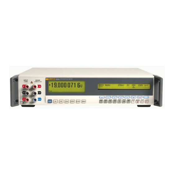
Getting Acquainted with the Basics Introduction Introduction Chapter 2 introduces the front and rear panel features of the 8508A Reference Multimeter (hereafter, referred to as the Multimeter). Figure 2-1 shows the Multimeter's front panel controls, indicators, and connectors. adj002f.eps Figure 2-1. Front Panel Displays Input Terminals XW Warning to avoid electric shock, personal injury, or death, never touch any lead... -
Page 28: The Front Panel Displays
8508A Users Manual The Front Panel Displays The front panel (Figure 2-1) has two displays: The display on the left, the main display, is used to show all measurement readings, with status legends on the bottom line, and measurement qualifiers on the line above. Figure 2-3 shows details of the main display, including annunciators. -
Page 29: Numeric Keyboard
Getting Acquainted with the Basics Front Panel Keys Numeric Keyboard adj012f.eps Numeric Keyboard The operation of the numeric keys is enabled for appropriate menus. The active keys are: DBGHJdNFAR numerals 0 to 9. decimal point polarity for exponent for backspace to enter the last reading taken to confirm the numeric entry to abort the numeric entry. -
Page 30: Direct Action Keys
8508A Users Manual Direct Action Keys adj017f.eps Direct Action Keys Press to disable internal triggers and enable all external trigger sources. The annunciator on the main display is lit. An external trigger for a measurement may be generated either by pressing the Sample key, by sending an appropriate trigger command via the IEEE-488 interface, or by a falling edge (TTL) at the External Trigger input on the rear panel. -
Page 31: Rear Panel
Getting Acquainted with the Basics Rear Panel Rear Panel adj018f.eps Figure 2-4. 8508A Rear Panel Detail Labels Attached to the rear panel are the identification label for the instrument, and a modification strike label. Fuses Located in the fuse drawer which is part of the integrated module for Power Fuse: power input and voltage selection. -
Page 32: Rear Panel Connectors And Pin Designations
8508A Users Manual Rear Panel Connectors and Pin Designations XW Warning This instrument can deliver a lethal electric shock. to avoid electric shock, personal injury, or death, never touch any lead or terminal unless you are absolutely certain that no dangerous voltage is present. -
Page 33: The 8508A-Lead Measurement Lead Kit
Getting Acquainted with the Basics The 8508A-LEAD Measurement Lead Kit The 8508A-LEAD Measurement Lead Kit XW Warning SAFE USE OF MEASUREMENT LEADS To avoid electric shock and potential injury or death, DO NOT use low voltage spade-terminated leads to connect to hazardous voltage (>32V ac rms or >... - Page 34 8508A Users Manual Four low thermal, PTFE insulated and shielded leads for signal applications. One heavy gauge lead for high current (> 2 A rms) applications. One hex key tool Two high integrity 4 wire zero PCBs 4 mm terminal post adaptors with hex key locking tool PTFE Lead Kit and Wallet* *General Purpose DMM Probe Kit is not shown...
-
Page 35: Making Measurements
Chapter 3 Making Measurements Title Page Introduction......................3-3 Making Connections to the Multimeter -- General Guidelines......3-4 Using the Measurement Functions............... 3-5 DC Voltage...................... 3-5 Measuring DC Voltage..................3-7 Making Input Connections................3-7 AC Voltage...................... 3-8 Measuring AC Voltage..................3-11 Induced Interference.................. - Page 36 8508A Users Manual Displaying Maximum, Minimum, and Peak-to-Peak Readings ...... 3-32 MAX Menu ....................3-32 Limit-Checking ................... 3-32 Monitor Menu Tree ..................3-33 Utility ........................3-33 Using the Selftest Functions ................3-36 Test Menu Tree....................3-36 Test Key ......................3-37 Using the Math Functions..................
-
Page 37: Introduction
Making Measurements Introduction Introduction XWWarning The Multimeter can deliver a lethal electric shock. To avoid electric shock, personal injury, or death, carefully read the information under "Safety Considerations" in Chapter 1 before attempting to install, use, or service the 8508A Reference Multimeter. A "XW Warning"... -
Page 38: Making Connections To The Multimeter -- General Guidelines
When connecting to a Multifunction Calibrator such impedance circuits. Separation of leads and as the Fluke 5720A or 5520A, follow the above creation of loops in the circuit can intensify the Guarding and Grounding advice and deselect disturbances. -
Page 39: Using The Measurement Functions
Making Measurements Using the Measurement Functions Using the Measurement Functions If you are unfamiliar with the front panel controls, review the relevant sections of Chapter 2. DC Voltage Press display the menu. DCV key to adj055f.eps DCV Menu This function provides both 2-wire and 4-wire measurements, in decade ranges from 200mV to 200V and a 1kV range. - Page 40 8508A Users Manual DCV Resolution Press the key to see the menu: Resl DCV RESL adj058f.eps DCV Resolution Menu 5-1/2-digits resolution 6-1/2-digits resolution 7-1/2-digits resolution 8-1/2-digits resolution To revert to the menu, press the key. DCV CONFIG CONFIG To revert to the menu from either , press the key.
-
Page 41: Measuring Dc Voltage
Making Measurements Using the Measurement Functions Measuring DC Voltage Making Input Connections Simple Lead Connection For the majority of applications the simple lead connection without external guard will be adequate. See Figure 3-1.The disadvantage of this simple arrangement is that the connecting leads can form a loop. -
Page 42: Ac Voltage
8508A Users Manual Internal Guard Connections not selected: The Guard terminals on the front and rear panels are External Guard isolated from each other and from any internal connection. The internal guard shields and tracks are connected directly to the internal 0V. selected: The internal guard shields and tracks are disconnected from the External Guard internal 0V, and connected to the... - Page 43 Making Measurements Using the Measurement Functions ACV Configuration (4 wire Sense, Resolution, RMS Filtering, Transfer mode, DC- Coupled and Spot Frequency) Press the key to see the menu. Config ACV CONFIG adj067f.eps ACV CONFIG Menu Allows operation with calibrators which provide a remote 4 wire sensing capability by providing, at an internal reference plane within the DMM, connections between and between...
- Page 44 8508A Users Manual ACV Resolution Press the key to see the menu: Resl ACV RESL adj068f.eps ACV RESL Menu 5-1/2-digits resolution 6-1/2-digits resolution To revert to the menu, press the key. ACV CONFIG Config ACV Filter Press the key to see the menu: Filt ACV FILT...
-
Page 45: Measuring Ac Voltage
Users should take care to avoid measurement errors from the interaction of lead capacitance and inductance with any source output impedance. Additional information and guidance is available in the Fluke publication Calibration: Philosophy in Practice (ISBN 0-9638650-0-5). Resistance Press to go to the OHM menu. - Page 46 8508A Users Manual OHMS Configuration (Resolution, Filter, Fast, Low Current and 4-Wire Operation) Press the key to see the menu. Config OHMS CONFIG adj074f.eps OHM CONFIG Menu Provides selection of the resolution for subsequent readings. Resl Controls a single-pole analog filter for increased noise rejection. Filt The Filter annunciator on the left-hand display indicates that the filter is active.
-
Page 47: High Voltage Ohms
Making Measurements Using the Measurement Functions Ohms - Movement between Menus CONFIG ON/OFF TOGGLE TOGGLE TOGGLE adj076f.eps Ohms Movement Between Menu High Voltage Ohms Press the key to see the expanded Ohms selection for True Ohms function and PLUS key to see the menu: the High Voltage Ohms function. - Page 48 8508A Users Manual XWCAUTION To avoid equipment damage when using the HiV function make sure that circuits or components connected to the Multimeter can withstand at least 240 V dc. HiV Configuration (Resolution, Filter, and 4-Wire Operation) Press the key to see the menu.
-
Page 49: True Ohms
Making Measurements Using the Measurement Functions HIV - Movement between Menus adj085f.eps Movement Between Menu True Ohms adj081f.eps Menu Press the key to see the expanded Ohms selection for True Ohms function and PLUS the High Voltage Ohms function. Press the Tru key for the Tru menu. -
Page 50: Measuring Resistance
8508A Users Manual TRU Resolution Press the key to see the menu: Resl TRU RESL adj083f.eps TRU RESL Menu 5-1/2-digits resolution 6-1/2-digits resolution 7-1/2-digits resolution 1/2-digits resolution Refer to table 3-1 for the ADC integration times applicable to the various resolution and Fast On/Off settings. -
Page 51: 4-Wire Measurements
Making Measurements Using the Measurement Functions INPUT HI INPUT HI INPUT LO INPUT LO GUARD adj091f.eps Figure 3-5. 2-Wire Measurements 4-wire Measurements With a 4-wire connection the lead resistances have negligible effect and only the value of Rx is displayed. INPUT HI SENSE HI INPUT HI... -
Page 52: 4-Wire Resistance Zero
8508A Users Manual 4-wire Resistance Zero For accurate measurements of resistance it is essential that a correctly connected zero source be used when performing an Input-Zero operation before making a series of measurements. The preferred arrangement shown in Figure 3-8 ensures that thermal and induced EMF effects, and bias current effects, associated with the multimeter and the measurement cables are eliminated. - Page 53 Making Measurements Using the Measurement Functions INPUT HI Metal Screen SENSE HI SENSE HI INPUT HI GUARD GUARD SENSE LO INPUT LO SENSE LO INPUT LO adj095f.eps Figure 3-9. Guard Measurements Internal Guard Connections not selected: In the Ohms or PRT Functions the Guard terminals on the External Guard front and rear panels are isolated from each other and from any internal connection.
-
Page 54: Dc Current
8508A Users Manual DC Current Press the key to show the menu. adj097f.eps DCI Menu This function provides measurements, in decade ranges from 200 A to 20A. (NOTE: the 20A range is only available on the front terminals. The front current terminal is not fused.) To cancel autoranging and enter a manually selected range, press any range Auto selection or the Auto softkey. -
Page 55: Measuring Dc Current
Making Measurements Using the Measurement Functions DC Current - Movement between Menus adj100f.eps Movement Between Menu Measuring DC Current Insert the Multimeter in the current path via its terminals, so that INPUT A INPUT Lo conventional current flows from Hi into the Multimeter's terminal and back the source Lo out of the... -
Page 56: Ac Current
8508A Users Manual AC Current Press the ACI key to show the ACI menu: adj101f.eps ACI Menu This function provides measurements, in decade ranges from 200 A to 20A. (NOTE: the 20A range is only available on the front terminals. The front current terminal is not fused.) To cancel autoranging and enter a manually selected range, press any range Auto... -
Page 57: Measuring Ac Current
Making Measurements Using the Measurement Functions ACI Filter Press the key to see the menu: Filt ACI FILT adj104f.eps ACI Filt Menu menu allows selection of one of four RMS filters. The indicated value is ACI FILT the lowest signal frequency that can be measured without degradation of accuracy or excessive reading variation. -
Page 58: Temperature
8508A Users Manual Note Lead Impedance - When making AC current measurements pay particular attention to the lead impedance, especially lead capacitance at high frequencies on the lower current ranges. (See "Measuring AC Voltage" earlier in this chapter.) Note Maximum Input Current capability and protection - The front input terminals may be used to measure currents up to 20 A. - Page 59 Making Measurements Using the Measurement Functions PROBE Configuration Management (New, Edit, Delete) adj107f.eps PROBE CONFIG Menu The utilization and management of PRT probe data is depends upon a probe identity. For example, before using the edit and delete capabilities a probe identity must be selected. For a new probe, defining an identity is the first step in the sequence of establishing the probe’s characteristics.
- Page 60 8508A Users Manual adj110f.eps Conversion Menu Select the conversion algorithm to be applied. This characteristic cannot be modified via . A measurement annunciator in the left-hand display indicates the Edit capability active conversion algorithm. This algorithm converts resistance to temperature according to the ITS-90 SPRT ITS90 specifications for SPRTs.
-
Page 61: Measuring Temperature
Making Measurements Using the Measurement Functions The Rtp is the resistance of the probe at the triple point of water. For a probe calibrated for the subrange W7 the coefficient is equivalent to , coefficient is equivalent to , and . -
Page 62: Multimeter Inputs
8508A Users Manual Multimeter Inputs Input key and its menu allow you to select either the Front or Rear panel terminals as Input the input to the Multimeter: The scan softkey gives access to dual-channel measurement and processing selection which produces a single result. Using the INPUT Key Press the key to see the... -
Page 63: Scan Operations
Making Measurements Multimeter Inputs SCAN OPERATIONS adj128f.eps Scan Menu In each of three Scan modes, measurements are taken alternately from the Front and Rear Terminals and are combined mathematically to produce a single result as shown below. Readings are taken alternately from the front terminals and then the rear to produce the displayed result;... -
Page 64: Tru Ohms Ratio
8508A Users Manual Caution HIGH VOLTAGE To avoid equipment damage when using the HiV function make sure that circuits or components connected to the Multimeter can withstand at least 240 V dc. Note Scan of Temperature Measurement - Scan Mode is not available in the PRT Function. -
Page 65: Monitoring Modes
Making Measurements Monitoring Modes Monitoring Modes Monitor Key Press the key to display menu: Monitor MONITOR adj116f.eps MONITOR menu Displaying Signal Frequency When measuring AC voltage or current, select the key to display the frequency Freq corresponding to the rms value shown on the main display. The response rate for the function frequency measurements can be set in the menu. -
Page 66: Displaying Maximum, Minimum, And Peak-To-Peak Readings
8508A Users Manual Displaying Maximum, Minimum, and Peak-to-Peak Readings , and menus have the same format and show information derived PKPK from measurements taken since the , or mode was reset. Pkpk Once one of the three menus has been entered, you can select either of the other two without going through the menu. -
Page 67: Monitor Menu Tree
Making Measurements Utility Monitor Menu Tree An overview of the mode and a diagram of the menu tree follows. Monitor Monitor ON/OFF STD DEVIATION = xxxxxxxx adj114f.eps Monitor Menu Tree Note From any of these menus, pressing the hard key will enter the Config menu;... - Page 68 8508A Users Manual Provides a contrast menu for adjustment to the right hand display. Right Di splay Provides selection of the power line frequency for the Multimeter. Line When in ACV function this softkey displays the menu to view the SpotF SPOTF spot frequencies at which the Multimeter has been calibrated.
- Page 69 Making Measurements Utility SER# Display adj123f.eps Ser# display This display is for information only. The serial number cannot be altered except in one of the calibration menus at the factory. The software issue number (last four digits) is embedded in the software itself, and is not user-alterable.
-
Page 70: Using The Selftest Functions
8508A Users Manual Status Reporting - Movement between Menus adj124.eps Status Reporting -- Movement Between Menus Using the Selftest Functions This section covers the Multimeter's selftest functions that can be performed via the Test key. An overview of the mode and a diagram of the menu tree is provided in Test Test... -
Page 71: Test Key
Making Measurements Using the Selftest Functions Test Key Press the key to display the menu, from which you can choose to perform a Test TEST variety of selftests. adj126f.eps TEST Menu menu allows you to initiate front panel display and key tests and ‘Circuit’ test. TEST The latter has either a standard single sequence of test or the capability to loop this sequence of tests. -
Page 72: Using The Math Functions
8508A Users Manual Using the Math Functions Math Functions and Menu Tree adj127f.eps Math Menu Tree Press the key to display the menu. The MATH menu provides selections for Math MATH a variety of linear, averaging, and logarithmic calculations. adj129f.eps MATH Menu Mathematical operations are performed on the readings obtained from the main measurement function in strict left-to-right order. -
Page 73: Math Configuration
Making Measurements Using the Math Functions Note From any of the menus below, pressing the key enters the Config MATH menu; pressing the key reverts to the menu. CONFIG Math MATH Press to revert automatically to the menu. Enter Quit MATH CONFIG Causes a rolling average of R readings to be made. -
Page 74: Clear Functions
8508A Users Manual Clear Functions adj143f.eps CLEAR Menu The ‘input zero’ corrections will remain active until power down, but the selections available in this menu will allow the corrections to be cleared. Removes the correction for the currently selected range and function. Rng Zero Removes the correction for all ranges for the currently selected Fnc Zero... -
Page 75: Remote Operations Using The Ieee 488 Interface
Chapter 4 Remote Operations Using the IEEE 488 Interface Title Page Introduction......................4-3 Interface Capability: IEEE Standards 488.1 and 488.2 ........4-3 The Multimeter in IEEE 488.2 Terminology ..........4-3 Programming Options ..................4-3 Capability Codes ..................... 4-3 Interconnections....................4-4 Using the 8508A Reference Multimeter in a System .......... - Page 76 8508A Users Manual Subtraction....................... 4-28 Division ......................4-29 Decibel Calculations..................4-30 Syntax Diagram of Test ..................4-31 Selftest ......................4-31 Device Errors and Syntax Diagrams..............4-31 Error Detection ....................4-31 Recall Device Errors..................4-32 Triggering and Reading Operations..............4-33 Trigger Source Selector ................... 4-33 Execute Trigger ....................
-
Page 77: Introduction
"Command, Queries, and Syntax Diagrams" later in this chapter. The material in this chapter is organized in the following categories: Interface Capability Introduction to the IEEE 488.1 subsets that are implemented in the Fluke 8508A, satisfying IEEE 488.2. Interconnections Description of the rear panel IEEE 488 connector and its pin designations. -
Page 78: Interconnections
8508A Users Manual Table 4-1. IEEE Interface Capability IEEE 488.1 Subset Interface Function Source Handshake Capability Acceptor Handshake Capability Talker (basic talker, serial poll, unaddressed to talk if addressed to listen) Listener (basic listener, unaddressed to listen if addressed to talk) Service Request Capability Remote/Local Capability (including Local Lockout) No Parallel Poll Capability... -
Page 79: Using The 8508A Reference Multimeter In A System
Remote Operations Using the IEEE 488 Interface Using the 8508A Reference Multimeter in a System Using the 8508A Reference Multimeter in a System Setting the Multimeter Address The Multimeter will only respond to Talk or Listen commands from the controller at a specified address. - Page 80 8508A Users Manual which are known as "Program Message Unit Separators". Thus the semi-colon cannot be used for any other purpose. As you can see from the diagram, multiple Program Message Units can be sent if they are separated using semi-colons (shown in the repeat path). The starting circle is used only for the diagram to indicate the start of a complete Program Message.
- Page 81 Remote Operations Using the IEEE 488 Interface Using the 8508A Reference Multimeter in a System Program Header Data Element adj201f.eps Program Header Separator - phs The Program Header The ‘Program Header’ provides the main command identification. This may be followed by ‘Program Data Elements’...
-
Page 82: The 8508A Status Reporting Structure
8508A Users Manual Note that the slash-delimited /^END/ box is not outlined. This is to draw attention to the fact that it is not a data element, but represents the EOI line being set true with the last byte NL to terminate the program message. digit user message digit... -
Page 83: Types Of Status Information Available
Remote Operations Using the IEEE 488 Interface Using the 8508A Reference Multimeter in a System Standard-Defined and Device-Specific Features In the 8508A, the structure has three main registers, as follows: The Status Byte Register, and its associated enable register, control the generation of the Status Byte, which summarizes the remainder of the status structure. -
Page 84: Dc Voltage
8508A Users Manual Device-Dependent Error - a reportable internal operating fault has been detected. Query Error - the controller is following an inappropriate message exchange protocol, in attempting to read data from the output queue. Request Control - provided for devices which are able to assume the role of controller. -
Page 85: Ac Voltage
Remote Operations Using the IEEE 488 Interface Syntax Diagrams of Major 8508A Functions A numeric value that selects the range for the expected signal. For example, an of 2, 10, or even 15.6789, selects the 20 V range. Any valid numeric value cancels autorange. AUTO Selects the autorange mode where the multimeter will determine the appropriate range for the measured signal. - Page 86 8508A Users Manual AC Voltage A numeric value that selects the range for the expected signal. For example, an of 2, 10, or even 15.6789, selects the 20 V range. Any valid numeric value cancels autorange. AUTO Selects the autorange mode where the multimeter will determine the appropriate range for the measured signal.
-
Page 87: Resistance: Normal Ohms
Remote Operations Using the IEEE 488 Interface Syntax Diagrams of Major 8508A Functions Recall of Spot Frequency Value SPOT? adj211f.eps Recall of Spot Frequency (Nr3) Recalls the frequency value for the specified calibrated spot on the active ACV range. Resistance: Normal OHMS The following commands are used to select the Normal function and set its OHMS... -
Page 88: Resistance: High Voltage Ohms
8508A Users Manual RESL5 / RESL6 / RESL7 / RESL8 Sets the resolution of the measurement to 5.5, 6.5, 7.5, or 8.5, digits. FAST_ON / FAST_OFF Reduces the A-D integration time, for faster conversions. FAST_ON TWO_WR Selects 2-wire Ohms (Use Hi and Lo terminals). (For backwards compatibility TWR can also be used.) FOUR_WR Selects 4-wire Ohms. -
Page 89: Resistance: True Ohms
Remote Operations Using the IEEE 488 Interface Syntax Diagrams of Major 8508A Functions TWO_WR Selects 2-wire Ohms (Use Hi and Lo terminals). (For backwards compatibility TWR can also be used.) FOUR_WR Selects 4-wire Ohms. (For backwards compatibility FWR can also be used.) Power On and Reset Conditions 20 M , FILT_OFF, RESL6, FAST_OFF, TWO_WR Resistance: True OHMS... -
Page 90: Dc Current
8508A Users Manual DC Current The following commands are used to select the function and set its configuration. A UTO FILT_ON FILT_OFF RESL5 RESL6 RESL7 FA ST_ON FA ST_OFF adj215f.eps DC Current A numeric value that selects the range for the expected signal. Any valid numeric value cancels autorange. -
Page 91: Ac Current
Remote Operations Using the IEEE 488 Interface Syntax Diagrams of Major 8508A Functions AC Current The following commands are used to select the function and set its configuration. A CI A UTO FILT100HZ FILT40HZ FILT10HZ FILT1HZ RESL5 RESL6 DCCP A CCP adj216f.eps AC Current A numeric value that selects the range for the expected signal. -
Page 92: Using Platinum Resistance Thermometers To Obtain Temperature
8508A Users Manual Using Platinum Resistance Thermometers to obtain Temperature. The following commands are used to select the function and set its configuration. identity DEG_K DEG_C DEG_F RESL5 RESL6 RESL7 RESL8 adj356f.eps Platinum Resistance Thermometers Identity This is a string value and thus must be enclosed in double quotes and must be identical in all respects with the identity of an already entered PRT. -
Page 93: Entering Or Editing The Characteristics Of A Prt To Non-Volatile Store
Remote Operations Using the IEEE 488 Interface Syntax Diagrams of Major 8508A Functions Entering or Editing the Characteristics of a PRT to Non-volatile Store The following commands are used to construct a identity and set associated parameters and coefficients. identity STD_PRT PRT_CHR TWO_WR... -
Page 94: Recalling The Characteristics Of A Known Prt
8508A Users Manual Execution Errors If the identity is unknown an error is generated for the coefficient entry. An error is generated if any of the coefficients exceed the limits for correct algorithm operation. Recalling the Characteristics of a Known PRT PRT_DATA? PRT_DATA? identity... -
Page 95: Input
Remote Operations Using the IEEE 488 Interface Syntax Diagrams of Major 8508A Functions Input The following commands are used to select an input; or combined usage of the two inputs to calculate the Ratio, Difference and Deviation measurement modes. The selections are mutually exclusive. -
Page 96: Measurement Gate Width
8508A Users Manual INT / EXT This selects the connection of the multimeter’s guarding. (For backwards compatibility LCL & REM can also be used.) For scan operations, the guard selection is applied to the channel currently being applied to the A-D converter. Power On and Reset Conditions INT (internal) Measurement Gate Width... - Page 97 Remote Operations Using the IEEE 488 Interface Syntax Diagrams of Major 8508A Functions PKPK? Obtains the stored value representing the difference between the maximum and minimum signal values to be measured since the most-recent general reset, store reset or function change.
-
Page 98: Limits
8508A Users Manual Limits Each command sets its corresponding limit, for comparison with each measurement when enabled. HILT LOLT adj223f.eps Setting Hi/Lo Limits A Decimal Numeric Data element that represents the mathematical value to be used for limit-checking. Its resolution is 8.5 significant digits; numbers in excess of this resolution will be rounded to it. -
Page 99: Standard Deviation
Remote Operations Using the IEEE 488 Interface Syntax Diagrams of Math Functions Standard Deviation Each of these queries recalls the stored standard deviations for a block of readings. DEVTN? READING DEVTN? ABSOLUTE adj363f.eps Recall Standard Deviation DEVTN? READING (Nr3) Recalls the standard deviation of the block relative to the mean of the block. DEVTN? ABSOLUTE (Nr3) Recalls the standard deviation of the block as an absolute quantity. - Page 100 8508A Users Manual Enable Averaging All selections are mutually exclusive. AV16 AV64 BLOC_N adj226f.eps Enable Averaging AVG AV... Averages the number of readings requested (4, 16, or 64) as a rolling average. Note From a cleared average memory, the average is the mean of the number of readings to date, until the selection window number is reached.
-
Page 101: Multiplication
Remote Operations Using the IEEE 488 Interface Syntax Diagrams of Math Functions Recall Block Size adj228f.eps Recall block Size (Nr1) Recalls the active value of "N". Multiplication Each signal value is multiplied by a user-defined factor "M". Enable Multiplication Selects the multiplication operation to be performed on the measurement. MUL_M adj229f.eps Enable Multiplication... -
Page 102: Subtraction
8508A Users Manual Recall Multiplication Constant adj231f.eps Recall Multiplication Constant ( Nr3) Recalls the defined value of M. Subtraction A user-defined constant "C" is subtracted from each signal value. Enable Subtraction Selects the subtraction operation to be performed on the measurement. SUB_C adj232f.eps Enable Subtraction... -
Page 103: Division
Remote Operations Using the IEEE 488 Interface Syntax Diagrams of Math Functions Recall Subtraction Constant adj234f.eps Recall Subtraction Constant (Nr3) Recalls the defined value of C. Division Each signal value is divided by a user-defined factor "Z". Enable Division Selects the division operation to be performed on the measurement. DIV _Z adj235f.eps Enable Division... -
Page 104: Decibel Calculations
8508A Users Manual Recall Division Constant adj237f.eps Recall Division Constant (Nr3) Recalls the defined value of z. Decibel Calculations Decibel operations calculate, and express in decibels, the ratio of the reading to one of four standard references: unity, and 1 mW in either 50 , 75 or 600 . -
Page 105: Syntax Diagram Of Test
Remote Operations Using the IEEE 488 Interface Syntax Diagram of Test Recall dB Reference Value DB_REF? adj240f.eps Recall dB Reference Value DB_REF? (Nr3) Recalls the current value of the DB_REF voltage. The value returned is the voltage value assigned to the program data elements: The element UNITY: +1.00000000E+00. -
Page 106: Recall Device Errors
8508A Users Manual A device-dependent error (DDE) is generated if the device detects an internal operating fault (e.g., during self-test). The DDE bit (3) is set true in the Standard-defined Event Status Byte, and the error code number is appended to the Device-Dependent Error queue. -
Page 107: Triggering And Reading Operations
Remote Operations Using the IEEE 488 Interface Triggering and Reading Operations EXQ? Recalls the last error from the queue of execution errors. An execution error occurs when a command cannot be complied with. Read the Queue until Empty. It is good practice to read the queue until empty on each occurrence of execution error, to prevent unrelated history of errors being retained. -
Page 108: Execute Trigger
8508A Users Manual Execute Trigger This command conforms to the IEEE 488.2 standard requirements. adj245f.eps Execute Trigger *TRG Equivalent to a Group Execute Trigger (GET). Causes a single reading to be taken. Execute Trigger and Take a Reading adj246f.eps Execute Trigger and Take Reading Equivalent to performing an Execute Trigger ( ) followed by a reading query. - Page 109 Remote Operations Using the IEEE 488 Interface Triggering and Reading Operations Delay Default Tables The delays listed in the following tables are active unless a specific delay is programmed. Once programmed, a specific delay will be applied to all subsequent readings providing External Trigger mode is selected until either the DELAY DFLT command is received, or the instrument is returned to local control.
-
Page 110: Input Zero
8508A Users Manual Input Zero Determines and corrects for the input zero and stores the result in volatile memory. An Input Zero is stored only for the input channel selected. Each input has its own set of Input Zero stores, for all of the applicable range/function combinations. For OHMS function an independent Input Zero should be executed for the two/four wire connection and for the low/normal current selection. -
Page 111: Access To The Internal Buffer Memory
Remote Operations Using the IEEE 488 Interface Triggering and Reading Operations Voltage, Current and Resistance Readings RDG? ( Nr3) Recalls the most recently triggered reading taken by the instrument. If no trigger has been received to generate a conversion of the input signal, then the response to this command will represent the most-recent measurement. - Page 112 8508A Users Manual stores 16 readings BLOCK 16 First reading Last reading 1 2 3 4 5 6 7 8 9 10 11 12 13 14 15 16 17 18 19 20 22 adj294f.eps Block of 16 readings At the completion of the block of measurements, bit 0 of the 8508A Status Byte is set, providing the appropriate bits of the Service Request Enable register (bit 0) and Measurement Event Status Enable register (bit 6) are set.
-
Page 113: Internal Operations Commands
Remote Operations Using the IEEE 488 Interface Internal Operations Commands Example: BLOCK 16 Locations of readings stored by 3 4 5 8 9 10 11 12 13 14 15 16 17 18 19 20 22 BLOCK? 6,11 recalls selected readings consecutively from the stored block: First reading Last reading 8 9 10 11... -
Page 114: Complete Operations
8508A Users Manual Complete Operations *OPC A synchronization command that generates an operation complete message in the standard Event Status Register when all pending operations have been processed by the parser. adj253f.eps Complete OPC? A synchronization command that places the ASCII character ‘1’ in the output queue when all pending operations have been processed by the parser. - Page 115 Remote Operations Using the IEEE 488 Interface Status Reporting Service Request SRE phs Nrf Enable Register SRE? STATUS BYTE STB? REGISTER Request for Service Bit Master Status Summary Bit Event Status Summary Bit Message Available Bit Measurement Event Status Summary Bit Event ESE phs Nrf Status Enable Register...
- Page 116 8508A Users Manual A number which, when rounded to an integer and expressed in base 2 (binary), enables the appropriate bits in this register. The detail definition is contained in the IEEE 488.2 document and in the status data structure diagram. Recall Service Request Enable SRE? adj263f.eps...
- Page 117 Remote Operations Using the IEEE 488 Interface Status Reporting ESE? (Nr1) Recalls the enable mask for the standard defined event register. The returned value, when converted to base 2 (binary), identifies the bits as defined in the IEEE 488.2 standard and detailed in the status data structure diagram. Power On and Reset Conditions The Power ON condition depends on the condition stored by the common *PSC command - if 0 then it is not cleared;...
-
Page 118: Instrument I/D And Setup
8508A Users Manual Power On and Reset Conditions Cleared (i.e., nothing enabled). Clear Status adj265f.eps Clear Status *CLS Clears all the event registers and queues except the output queue. The output queue and MAV bit will be cleared if *CLS immediately follows a '"Program Message Terminator". - Page 119 Remote Operations Using the IEEE 488 Interface Instrument I/D and Setup Response The data contained in the four comma separated fields is organized as follows: First field - Manufacturer Second field Model Third field - Serial number Fourth field - Firmware level (issue.revision).
-
Page 120: Calibration Commands And Messages
8508A Users Manual LINEF? (Nr1) Recalls the active setting for line frequency. Calibration Commands and Messages XWCaution The descriptions in the following pages are intended only as a guide to the messages available to calibrate the instrument. They contain neither examples nor calibration routines, and should NOT be used directly as a basis for calibrating any part of the instrument. - Page 121 Remote Operations Using the IEEE 488 Interface Calibration Commands and Messages Trigger "External Calibration" CAL? adj272f.eps Trigger External Calibration CAL? Triggers an external calibration event, including the "SET" feature used for local calibration. A numeric value representing the "SET" calibration value. This is used as the target for the actual measured value.
-
Page 122: Protected User Data
8508A Users Manual Calibration Due Date EXT_DUE? adj275f.eps Calibration Due Date EXT_DUE? (String) Returns the user-entered recommended date for the re-calibration of the instrument. The date is that most-recently entered either as a parameter of EXITCAL, or when an exit was made from the front panel calibration mode. Protected User Data Entry of User Data user message... -
Page 123: Special Calibrations
Remote Operations Using the IEEE 488 Interface Calibration Commands and Messages Response Syntax user message digit digit adj279f.eps Response Syntax where: digit one of the ASCII-coded numerals user message the saved user message Special Calibrations Perform a "Special" Calibration A DC CHSE? FREQ HV_LIN... - Page 124 8508A Users Manual "Special" measurement commands for DCV Linearity Calculations S R C _ N 1 K HV_LIN? SRC_N500 ZERO SRC_P500 SRC_P1K adj361f.eps "Special" measurement commands for DCV Linearity Calculations HV_LIN? Triggers a measurement and records the result for use with the special calibration command CHSE? HV_LIN.
- Page 125 Remote Operations Using the IEEE 488 Interface Calibration Commands and Messages Exit from Calibration " " EXITCAL date string date string Exit from Calibration adj284f.eps EXITCAL Exits calibration mode giving the operator the option of entering a due date, or bypassing it as shown in the syntax diagram.
- Page 126 8508A Users Manual Clear Calibration Memory A LL CLRMEM HFTRIM adj289f.eps Clear Calibration Memory CLRMEM Clears the calibration correction memories. XWCaution This command can obliterate the results of an expensive original calibration or re calibration! The extent of clear is defined by programming the following options: Clears all HFTRIM Clears AC HF frequency response correction only.
-
Page 127: Specifications
Chapter 5 Specifications Title Page Specifications....................... 5-3 General Specifications..................5-3 Maximum Voltage and Current Inputs............5-4 DC and AC Voltage ..................5-4 DC and AC Current..................5-4 Resistance and Temperature ............... 5-4 DC Voltage...................... 5-5 DC Current ...................... 5-6 AC Voltage...................... 5-7 AC Current ...................... - Page 128 8508A Users Manual...
-
Page 129: Specifications
Specifications Specifications Specifications General Specifications Power Voltage 115 V Setting ............. 100 V to 120 V rms 10 % 230 V Setting ............. 200 V to 240 V rms 10 % Frequency ............... 47 Hz to 63 Hz Consumption............< 80 VA Dimensions Height.............. -
Page 130: Maximum Voltage And Current Inputs
8508A Users Manual Maximum Voltage and Current Inputs Notes to maximum voltage and current input specifications Maximum DC input equal to maximum rms input. Maximum peak input is rms x 1.414 Specifications apply equally to front and rear input terminals except where noted below. Front to rear isolation allows opposing polarity of maximum terminal voltage on each input. -
Page 131: Dc Voltage
Specifications Specifications DC Voltage [1] [2] [3] DC Voltage Uncertainty Relative to Cal Stds Absolute Uncertainties ± (ppm Reading + ppm Range) [15] Range Full Scale 24 hour 90 day 365 day 365 day 365 day TCal TCal ±1 °C TCal ±1 °C TCal ±1 °C TCal ±1 °C... -
Page 132: Dc Current
8508A Users Manual DC Current [1] [2] [3] DC Current Uncertainty Relative to Cal Stds Absolute Uncertainties ± (ppm Reading + ppm Range) [15] Range Full Scale 24 hour 90 day 365 day 365 day 365 day TCal ±1 °C TCal ±1 °C TCal ±1 °C TCal ±1 °C... -
Page 133: Ac Voltage
Specifications Specifications AC Voltage [1] [2] [6] [7] AC Voltage Uncertainty Relative to Cal Stds Absolute Uncertainties ± (ppm Reading + ppm Range) [15] Range Full Scale Frequency (Hz) 24 hour 90 day 365 day 365 day 365 day TCal ±1 °C TCal ±1 °C TCal ±1 °C TCal ±1 °C... - Page 134 8508A Users Manual [1] [2] AC Voltage (Secondary Specifications) Temperature Coefficient 5 °C - 15 °C Range Frequency (Hz) 15 °C - 30 °C 30 °C - 40 °C ± ppm Reading/°C 200 mV 1 - 10 10 - 40 40 - 100 100 - 2 k 2 k - 10 k...
-
Page 135: Ac Current
Specifications Specifications AC Current [1] [2] [6] [9] AC Current Uncertainty Relative to Cal Stds Absolute Uncertainties Frequency ± (ppm Reading + ppm Range) [15] Range Full Scale (Hz) 24 hour 90 day 365 day 365 day 365 day TCal ±1 °C TCal ±1 °C TCal ±1 °C TCal ±1 °C... - Page 136 8508A Users Manual [1] [2] [6] [9] AC Current (Secondary Specifications) Temperature Coefficient Input Impedance ( ) 5 °C - 15 °C Range Frequency (Hz) 15 °C - 30 °C 30 °C - 40 °C ± ppm Reading/°C Range Front Rear 1 - 10 200 A, 2 mA...
-
Page 137: Resistance
Specifications Specifications Resistance [1] [2] [3] [9] Resistance Uncertainty Relative to Cal Stds Absolute Uncertainties ± (ppm Reading + ppm Range) [15] [10] Range Full Scale Mode 24 hour 90 day 365 day 365 day 365 day TCal ±1 °C TCal ±1 °C TCal ±1 °C TCal ±1 °C... - Page 138 8508A Users Manual [1] [2] [3] [10] Resistance - Normal Mode (Secondary Specifications) Temperature Coefficient Transfer Uncertainty 20 mins ±1 °C 5 °C - 15 °C Range Measurement Current 15 °C - 30 °C ± (ppm Reading 30 °C - 40 °C + ppm Range) ±...
-
Page 139: Temperature
Specifications Specifications Temperature [1] [2] [3] Temperature Readout [12] Typical Equivalent Temperature Measurement Uncertainty Absolute Resistance Measurement Uncertainty Nominal Resistance Range Resistance Accuracy 365 day Tcal ±1 °C Probe Type Temperature ± (°C) [11] ±(ppm Reading + m ) (°C) 95% Confidence Level 7.5 + 0.14 -200... -
Page 140: Read Rate And Additional Uncertainty
1.0 + 0.5 0 + 5 Notes to Performance Specifications Fluke guarantees 8508A performance verification using specifications stated to 99 % confidence level. [1] Specifications apply for max resolution in each function, normal mode [2] Assumes 4 hour warm-up period [3] Input zero or offset null required whenever the temperature moves more than ±1 °C from the temperature at which the previous... -
Page 141: Applying The Specifications
Applying the Specifications Introduction The Fluke 8508A has been designed specifically for metrologists. Not only does it provide the performance metrologists need, but it is specified in a way to allow users to really understand the uncertainties of the measurements, and easily make allowance for those uncertainty contributions when performing measurement uncertainty analyses and compiling uncertainty budgets. -
Page 142: Applying User's Calibration Uncertainties
23 C, the temperature at which the 8508A is calibrated by Fluke during manufacture and service. The 8508A is also capable of being calibrated at any temperature between 20 C and 25 C and the 1 C specifications will apply to operation within 1 C of that calibration temperature. -
Page 143: Ratio Measurements
Specifications Applying the Specifications Ratio Measurements The 8508A Ratio mode will automatically take measurements of inputs applied to the front and rear terminals and display the result as a ratio in the voltage and resistance functions. The measurements can be made on the same range or different ranges. When making measurements on different ranges the error in each measurement is evaluated by applying the relevant specification for each range and combining the two specifications in an RSS summation, expressing the contributions in parts-per-million of the measured... - Page 144 8508A Users Manual 5-18...
-
Page 145: Calibration And Verification
Chapter 6 Calibration and Verification Title Page Introduction......................6-3 Calibration Overview................... 6-3 Calibration Interval and Performance ..............6-3 Calibration Points ....................6-3 Non-Nominal Values..................6-4 Enabling Access to Calibration Mode ..............6-4 Calibration Menus....................6-4 Accessing the Calibration Menus and Calibration Mode ........ 6-4 Calibration Menu..................... - Page 146 8508A Users Manual Preparation....................... 6-32 DC Voltage Checks ..................6-32 AC Voltage Checks ..................6-34 Resistance Checks ................... 6-36 DC Current Checks..................6-39 AC Current Checks..................6-40 Frequency Checks ................... 6-42...
-
Page 147: Introduction
Many 8508A owners prefer using Fluke calibration services instead of maintaining their own standards to support their 8508A.To help ensure optimum performance from the 8508A, Fluke offers our calibration service at a variety of worldwide locations. Our worldwide service network provides fast efficient calibration to ensure low uncertainties and optimum accuracy consistent with the original calibration at manufacture. -
Page 148: Non-Nominal Values
8508A Users Manual Non-Nominal Values facility allows the user to set the calibration target to the value of the calibration source available. This facility is most useful when the user’s calibration source is not available at the nominal values specified, or when the user has knowledge of the actual output of the calibration source at the required points. -
Page 149: Set Value Menu
Calibration and Verification Calibration Menus adj134f.eps CALIBRATION Menu This menu defines four menu keys: Indicates to the user that the calibration point is automatically set according Auto to the amplitude (and frequency in ACV) of the signal detected. Auto is the default selection on entry to the menu. -
Page 150: Spot Cal Menu
8508A Users Manual SPOT CAL Menu This menu is obtained by pressing the Set key in the CALIBRATION menu when the 8508A is in ACV Spot Frequency mode. It provides a means of calibrating the 8508A at any of six user-specific spot frequencies, at non-nominal calibration values for each ACV range. -
Page 151: Special Calibration
Calibration and Verification Calibration Menus Calibrate the spot at a new frequency: To calibrate the spot at a new frequency, change the input signal to the desired new frequency and press as before. SAMPLE Reverts to the menu with the original Spot calibration intact. Quit SPOT CAL Special Calibration... -
Page 152: Hvlin Menu
8508A Users Manual adj138f.eps SER# Menu menu provides the selection: SER# Stores the new serial number, de-activates the keyboard, and reverts to the Enter SPCL menu. Reverts to the SPCL menu, leaving the old serial number intact. Quit Hvlin Menu This menu sequence is obtained by selecting from the SPCL menu. -
Page 153: Routine Calibration
This routine calibration procedure describes the calibration points and sequence of operations required to calibrate the 8508A and assumes calibration references of adequate traceable uncertainty are available – in this case a Fluke 5720A calibrator and 5725A amplifier used with an 8508A-7000 Calibration Kit. The procedure assumes the user is able to calibrate and characterize the calibration standards, without describing the process required to do so. -
Page 154: Equipment Required For Calibration
Equipment Required Fluke 5720A Multifunction Calibrator Fluke 5725A Amplifier Fluke 8508A-7000K Calibration kit comprising 1 G Standard, two precision low thermal emf 4-wire short devices, and connecting leads. Availability of a 1 MHz frequency reference signal may be required for 5720A frequency locking during 8508A frequency calibration procedure. -
Page 155: Interconnections
When calibrating the 2 G and 20 G resistance ranges the 1 G standard resistor supplied in the Fluke 8508A-7000K Calibration kit plugs directly into the 8508A front input terminals, without any interconnecting leads. If alternate resistance standards are used for resistance calibration, refer to the resistance-measurements section of Chapter 3 Making Measurements for connection details. - Page 156 8508A Users Manual The Fluke 8508A-7000K Calibration kit also contains two precision low-thermal emf 4-wire shorting devices for use when performing the non-volatile input offset adjustments at the front and rear input terminals. These devices link the input terminals in the following order: Input Lo to Input Hi to Sense Hi to Sense Lo.
-
Page 157: Adc Calibration
Calibration and Verification Routine Calibration ADC Calibration ADC (analog to digital converter) calibration aligns the different resolutions available from the 8508A analog to digital converter, so that there are no significant differences in readings when changing resolutions with a constant input value. It is recommended that is only performed if performance verification indicates significant resolution ADC CAL differences. - Page 158 8508A Users Manual Range Zero and Gain Calibration Procedure After the initial setup and connecting up, use the following procedure to calibrate range zero, then positive and negative range gains on all DCV ranges. Just one range can be calibrated if required, but for a full calibration start with the 200 mV range and work up to the 1kV range, as shown in Table 6-3.
-
Page 159: Ac Voltage Calibration
Calibration and Verification Routine Calibration Range Gain Points 1. On the Calibrator, select the positive Range Gain point Output value. 2. On the 8508A, Press to revert to menu. CALIBRATION 3. Select on the CALIBRATION menu 4. Use the numeric keys with the menu to key in the true output value of SET VALUE the calibrator at the range gain value, then press Enter. - Page 160 8508A Users Manual Table 6-4. AC Voltage Calibration Points and Sequence 8508A Range Point Voltage Frequency 200 mV Zero (5 % Range) 10 mV 1 kHz Range Gain LF 100 mV 1 kHz Range Gain HF 100 mV 60 kHz Zero (0.5 % Range) 10 mV 1 kHz...
-
Page 161: Resistance Calibration
Calibration and Verification Routine Calibration Resistance Calibration When calibrating the resistance function, each of the resistance modes (Normal, LoI, Tru , Tru LoI and HiV ) must be individually calibrated. The following procedure assumes use of a multifunction calibrator and calibrates each resistance mode in turn, range by range. - Page 162 8508A Users Manual Initial Setup and Connections 1. Press the key and select the range. 2. Press the key and select CONFIG Filt 3. In calibration mode the resolution defaults to in the resistance function. It is RESL7 recommended that this resolution is used for calibration of all resistance ranges. 4.
- Page 163 Calibration and Verification Routine Calibration Range Gain Point 1. On the Calibrator, select the Range Gain point resistance value. Alternatively if using a standard resistor re-connect the standard resistor to measure its resistance. (For the 2 G range the 8508-7000K 1 G standard resistor is used in place of the calibrator. For the 200 M and 2 G ranges, de-select EX SNS on the calibrator and de-select n the 8508A.) 2.
- Page 164 8508A Users Manual Zero Point 1. On the 8508A, select the required range. 2. On the Calibrator, select zero and Operate. Alternatively if using a standard resistor connect the standard resistor for a 4-wire resistance zero. (For the 200 M and 2 G ranges, de-select Ex SNS on the calibrator and de-select n the 8508A.)
- Page 165 Calibration and Verification Routine Calibration Zero Point 1. On the 8508A, select the required range. 2. On the Calibrator, select zero and Operate. Alternatively if using a standard resistor connect the standard resistor for a 4-wire resistance zero. 3. On the 8508A, press to enter the menu.
- Page 166 8508A Users Manual Zero Point 1. On the 8508A, select the required range. 2. On the Calibrator, select zero and Operate. Alternatively if using a standard resistor connect the standard resistor for a 4-wire resistance zero. 3. On the 8508A, press to enter the menu.
- Page 167 Calibration and Verification Routine Calibration For the 2 G range use the 1 G standard resistor in place of the calibrator. To avoid the requirement for a 10 G standard, the 20 G range is automatically calibrated when the 2 G range gain calibration is triggered. It is also necessary for the 100 M and 1 G Normal ranges to be calibrated prior to the 2 G HiV range for the result to be valid.
-
Page 168: Dc Current Calibration
8508A Users Manual 5. Press to initiate the calibration operation. SAMPLE Calibration is complete when the Busy legend goes out and the calibrated measurement is displayed. 6. On the Calibrator, set STANDBY 7. Press the key to revert to the ranges menu. DC Current Calibration XW Warning The Calibrator can deliver a lethal electric shock. - Page 169 Calibration and Verification Routine Calibration Table 6-6. DC Current Calibration Points and Sequence 8508A Range Point Current 200 A Zero Range Gain +ve +100 A Range Gain -ve -100 A 2 mA Zero 0 mA Range Gain +ve +1 mA Range Gain -ve -1 mA 20 mA...
-
Page 170: Ac Current Calibration
8508A Users Manual Range Gain Points 1. On the Calibrator, select the positive Range Gain point Output value. 2. On the 8508A, Press to revert to menu. CALIBRATION 3. Select on the CALIBRATION menu 4. Use the numeric keys with the menu to key in the true output value of SET VALUE the calibrator at the range gain value, then press Enter. -
Page 171: Frequency Calibration
Calibration and Verification Routine Calibration Table 6-7. AC Current Calibration Points and Sequence 8508A Range Point Current Frequency Zero (5 % Range) 300 Hz 200 A 10 A Range Gain 300 Hz 100 A 2 mA Zero (0.5 % Range) 300 Hz 10 A Range Gain... -
Page 172: Exit From Calibration Mode And Non-Volatile Input Offset Adjustment
8508A Users Manual Initial Setup and Connections 1. Press the key, select the range. 2. Confirm that the 8508A is configured for internal guard (External Guard is deselected) by checking that the legend does not appear on the left-hand Ext Grd display. -
Page 173: Cal Due Date Entry And Calibration Mode Disable
Calibration and Verification ACV Spot Frequency Calibration 8. Press the key, select and de-select . Repeat steps 3 and 4. CONFIG 9. Press the key and select . Repeat steps 3 and 4. CONFIG 10. Press the key and select . -
Page 174: Performance Verification
This routine performance verification procedure describes the test points and sequence of operations required to check the 8508A and assumes calibration references of adequate traceable uncertainty are available – in this case a Fluke 5720A calibrator and 5725A amplifier used with an 8508A-7000 Calibration Kit. The procedure assumes the user is able to calibrate and characterize the calibration standards, without describing the process required to do so. -
Page 175: Equipment Requirements
Fluke). It is recommended that these tolerances only be used for verification of the 8508A following calibration by Fluke, and if the above time period and temperature conditions are met. No allowance has been made for the uncertainty of the equipment used for verification. -
Page 176: Preparation
In such cases 8-digit mode can be selected and the specifically borderline verification tests can be repeated. This will provide additional confidence in the in-tolerance or out-of-tolerance decision made during verification. * Fluke guarantees 8508A performance verification using specifications stated to 99 % confidence level. Preparation 1. - Page 177 Calibration and Verification Performance Verification 3. On the 8508A press the key, and select to initiate the zeroing INPUT Zero Rng operation. legend will appear, and then extinguish when the zero operation has Busy completed. 4. On the calibrator select the value required for verification in the positive polarity. 5.
-
Page 178: Ac Voltage Checks
8508A Users Manual AC Voltage Checks XW Warning The Calibrator can deliver a lethal electric shock. To avoid electric shock when performing the following calibration procedures: Never touch any lead or terminal unless you are absolutely certain that no dangerous voltage is present. Make sure that signal leads are in a safe condition before you handle them in any way. - Page 179 Calibration and Verification Performance Verification Table 6-9. AC Voltage Verification Points and Sequence 8508A Range Voltage Frequency 8508A Filter Tolerance 200 mV 100 mV 20 Hz 10 Hz 0.0195 mV 100 mV 55 Hz 40 Hz 0.0175 mV 100 mV 1 kHz 100 Hz 0.0149 mV...
-
Page 180: Resistance Checks
8508A Users Manual Table 6-9. AC Voltage Verification Points and Sequence (cont) 8508A Range Voltage Frequency 8508A Filter Tolerance 200V 100 V 20 Hz 10 Hz 0.0144 V 100 V 55 Hz 40 Hz 0.0119 V 100 V 1 kHz 100 Hz 0.0099 V 100 V... - Page 181 Calibration and Verification Performance Verification Procedure Perform the following sequence for each resistance mode and each range, as listed in Table 6-10, starting with the 2 range and working up to the 2 G range for the Normal and Normal LoI resistance modes. Then continue the sequence for the Tru and Tru LoI modes, starting with the 2 range and working up to the 20 k range.
- Page 182 8508A Users Manual 11. Press the key and select , and CONFIG Filt RESL7 12. Repeat steps 3 – 9 for the Normal LoI ranges. 13. Press the key and select Plus Tru . 14. Press the key and select , and .
-
Page 183: Dc Current Checks
Calibration and Verification Performance Verification Table 6-10. Resistance Verification Points and Sequence (cont) 8508A Range Resistance Tolerance 20 M Perform input zero operation to calibrator range locked zero output 10 M 0.000202 M 200 M Perform input zero operation to calibrator range locked zero output 100 M 0.00870 M Perform input zero operation to calibrator range locked zero output... -
Page 184: Ac Current Checks
8508A Users Manual 6. On the calibrator select the value required for verification in the negative polarity. 7. Note the 8508A reading. Compare the result with the allowable tolerance, taking into account any known error from nominal of the calibrator for this output. Table 6-11. - Page 185 Calibration and Verification Performance Verification Procedure Repeat the following sequence for each range, starting with the 200 A range and working up to the 20A range, as listed in Table 6-12. 1. Select the required 8508A range. 2. On the calibrator set the output to the current and frequency for the point being verified as listed in Table 6-12.
-
Page 186: Frequency Checks
8508A Users Manual Frequency Checks Equipment Configuration 1. Ensure that the calibrator output is set to STANDBY and configured for Internal Guard (EXT GRD is deselected). 2. Connect the equipment as described for Routine Calibration. 3. Press the ACV key, select the 2V range 4. -
Page 187: A Error Codes And Message
Appendix A Error Codes and Message Introduction Note For the sake of completeness, this appendix collects together the error codes which might be generated either on the instrument front panel, or via the IEEE 488 system bus. Error Detection Errors are classified by the method with which they are handled: Recoverable errors are reported to the user and the Multimeter continues operation. - Page 188 8508A Users Manual Recoverable Errors Recoverable errors consist of: Command Errors Execution Errors Device-Dependent Errors Command Errors can only be generated due to incorrect remote programming. Some Execution Errors and all Device-Dependent Errors can all be generated by manual operation as well. Each of the reportable Execution and Device-Dependent Errors are identified by a code number.
- Page 189 Appendix Error Codes and Message Device-Dependent Errors (DDE) A Device-Dependent Error is generated if the device detects an internal operating fault (e.g., during self-test). The DDE bit (3) is set true in the Standard-defined Event Status Byte, and the error code number is appended to the Device-Dependent Error queue. In remote mode operations, the error is reported by the mechanisms described in the sub- section of Chapter 4 that deals with status reporting, and the queue entries can be read destructively as LIFO by the Common query command DDQ?.
- Page 190 Self-Test Errors These self-test error numbers will appear only if the test has not been successful, and should be reported for interpretation to your local Fluke service center, so that the fault can be analyzed. A short description of the test step is also given.
- Page 191 Appendix Error Codes and Message AC Volts Tests 2801 100mV AC Range: Zero Input Check. 2811 100mV AC Range: +179mV DC Input Checks at Pre-Amp Output 2821 100mV AC Range: -179mV DC Input Checks at Pre-Amp Output 2831 1V AC Range: Zero Input Check. 2841 1V AC Range: +993mV DC Input Checks at Pre-Amp Output 2851...
- Page 192 8508A Users Manual...
-
Page 193: Rack Mount Kit
Appendix B Rack Mount Kit Introduction A Rack Mount Kit for mounting the Multimeter in a standard 19-inch equipment rack is available as an Option. For instructions on how to install the kit and mount the Multimeter in the equipment rack refer to Figure B-1 and the following procedure. - Page 194 8508A Users Manual 6. Fit the instrument to the rack as follows: a. Attach the two rear rack-mount ears to the back of the equipment rack so they are ready to receive the instrument. b. With assistance, slide the instrument into the rack, positioning the extension of the rear rack-mount ears in each side-cover strip opening.
-
Page 195: C Rack Mount Slide Kit
Appendix C Rack Mount Slide Kit Introduction A Rack Mount Slide Kit for mounting the Multimeter in a standard 19-inch equipment rack is available as an Option. For instructions on how to install the kit and mount the Multimeter in the equipment rack refer to Figure C-1 and the following procedure. - Page 196 8508A Users Manual 6. Fit the instrument to the rack as follows: a. Attach a pair of rack-mount ears and a slide-rail to each side of the equipment rack so they are ready to receive the instrument. b. With assistance, and from the front of the equipment rack, insert the end of each slide bar (on the Multimeter) into the appropriate slide-bar on the equipment rack.