Table of Contents
Advertisement
Advertisement
Table of Contents

Related Manuals for ABB ANR96


Summary of Contents for ABB ANR96
- Page 1 ANR96 LECTRICAL ULTIFUNCTION NALYZER ANR96 ETWORK NALYZER User Manual IM 125-U v. 4.4 ANR96 IM125-U-A v4.4.doc ABB S.p.A. Divisione SACE Apparecchi Modulari Viale dell’ industria, 18 20010 Vittuone (MI) – Italy Tel.: 02.9034.1 – Telefax: 02.9034.7609 http://bol.it.abb.com...
- Page 2 The information contained herein is the property of ABB SpA, and by law, no part of it may be reproduced, transcribed, stored in any retrieval system, or translated into any language by means (even for internal purposes by the customer) without the express written permission of ABB SpA.
-
Page 3: Table Of Contents
ANR96 - USER MANUAL INDEX MAIN INFORMATION _________________________________________________________5 1.1) INTRODUCTION _________________________________________________________5 1.2) DESCRIPTION __________________________________________________________5 1.3) CE CONFORMITY AND STANDARDS _______________________________________5 TECHNICAL FEATURES ______________________________________________________6 2.1) GENERAL SPECIFICATIONS ______________________________________________6 2.2) MEASURING METHOD AND ACCURACY ____________________________________8 2.3) MEASURED VARIABLES _________________________________________________9 2.4) CALCULATED VARIABLES _______________________________________________9 2.5) - Page 4 ANR96 - USER MANUAL 8.4) SERIAL PORTS ________________________________________________________26 8.4.1) STANDARD SERIAL PORT ______________________________________________26 8.4.2) RS485 CONNECTION NOT SHIELDED ____________________________________27 8.4.3) RS485 CONNECTION SHIELDED _________________________________________27 8.4.4) RS232 CONNECTION __________________________________________________28 8.4.5) MODEM CONNECTION _________________________________________________29 8.4.6) OPTION RS485 PORT __________________________________________________30 8.5) OPTION PROFIBUS PORT _______________________________________________31 8.6)
-
Page 5: Main Information
1.2) DESCRIPTION The ANR96 is an instrument which has been designed to monitor, store and analyze all electrical variable in a distribution line. All the relevant data are displayed and, if desired, stored on internal RAM and transmitted to a remote PC, via RS485 (standard) on which the compatible management software has been installed. -
Page 6: Technical Features
ANR96 - USER MANUAL TECHNICAL FEATURES 2.1) GENERAL SPECIFICATIONS Power supply/Auxiliary voltage 85-265 V 50/60 Hz/dc. 20-60 V 50/60 Hz/dc (option). Isolation voltage 3700 Vac rms x 1 minute. Voltage input 3 inputs, range 10-600Vrms between phase-phase. Over voltage up to 750 Vac permanent, beyond this value it is imperative to use voltage transformers. - Page 7 ANR96 - USER MANUAL Options: - N°2 digital outputs 12-230 Vac-dc / 150mA max. The typical resistance with closed contacts is 8Ω (R = 12Ω). Maximum frequency pulse emission: 16Hz. ONmax - N°2 relay outputs The relay specifications are the following:...
-
Page 8: Measuring Method And Accuracy
ANR96 - USER MANUAL 2.2) MEASURING METHOD AND ACCURACY Measuring range 30-500Hz. Measuring method 64 sampling per period for V1 and I1, V2 and I2, V3 and I3. Measuring interval 0,1 second. Instrument accuracy Model ANR96 Model ANR96-02 Voltage < 0.5 % <... -
Page 9: Measured Variables
ANR96 - USER MANUAL 2.3) MEASURED VARIABLES PHASE VOLTAGE (Rms) L1-N L2-N L3-N LINE CURRENT (Rms) FREQUENCY (Hz) TEMPERATURE T(°C) 2.4) CALCULATED VARIABLES LINE VOLTAGE (Rms) L1-L2 L2-L3 L3-L1 THREE-PHASE SYSTEM VOLTAGE (Rms) THREE-PHASE SYSTEM CURRENT (Rms) AVERAGE THREE-PHASE SYSTEM CURRENT... -
Page 10: Measuring & Calculation Formulas
ANR96 - USER MANUAL 2.5) MEASURING & CALCULATION FORMULAS ∑ L iN k Phase Voltage V L iN ∑ L iN k Line Current I L i ⋅ ∑ iN k Active Power W L i ⋅ ∑ Δ −... - Page 11 ANR96 - USER MANUAL ∞ ∫ Reactive Energy ∑ L ij k Line Voltage V L ij Phase Line Voltage V Φ Phase System Current I Φ Phase Active Power W Φ Phase Reactive Power Q Φ PhaseAppea rent A Φ...
-
Page 12: Instrument Description
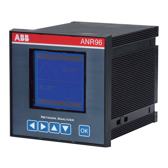
ANR96 - USER MANUAL INSTRUMENT DESCRIPTION The front panel of the ANR96 is described on the following section: ANR96 ETWORK NALYZER 1 DISPLAY Back lighted graphic LCD 50x50mm, 128x128 dot, dot pitch 0.35mm x 0.35mm, dot size 0.32mmx0.32mm, high viewing direction 60°, positive and negative visualization at low reflection. -
Page 13: Installation
ANR96 - USER MANUAL INSTALLATION 4.1) SAFETY On receipt of the instrument and prior to installation, make sure it is intact and has not been damaged during shipment. Before installing, make sure the operating voltage and mains voltage are compatible. -
Page 14: Mounting
ANR96 - USER MANUAL 4.3) MOUNTING The unit needs to be installed on front panel of mains control/switchboards, wiring and connections must be carried out following the EMC (Electro-Magnetic-Compatibility) procedures. Plug in screw terminal blocks are used for appropriate wiring. There is a security locking on the current inputs terminal block. -
Page 15: Internal Battery
ANR96 - USER MANUAL INTERNAL BATTERY To avoid to lose the setup and all storing data, the instrument is equipped of an internal battery (CR2450). 5.1) REPLACEMENT INTERNAL BATTERY Only a qualified and authorized technical person can change the internal battery. -
Page 16: Connection
ANR96 - USER MANUAL CONNECTION Do2- Do2+ Ao2- Do3- Ao2+ Do3+ Ao1- Ao1- Do4- Ao1+ Ao1+ Do4+ S1 S2 6.1) POWER SUPPLY The instrument doesn’t work without power supply. Before powering the instrument verify always to insert the right value (85-265 Vac/dc standard;... -
Page 17: Voltage Inputs
Connect the instrument following up the wiring diagrams described on chapter 6.4). ANR96 was developed and tested in accordance with IEC 348 class 1 standards for operating voltages up to 600 Vac rms. 6.3) CURRENT INPUTS Connect the instrument following up the wiring diagrams described on chapter 6.4). - Page 18 ANR96 - USER MANUAL ANR96 ETWO RK NA LYZER inserzione su linea a 4 fili con n°3 TA e n°3 TV ANR96 ETWO RK NA LYZER inserzione su linea a 4 fili con n°3 TA in bassa tensione ...
-
Page 19: Option Boards
ANR96 - USER MANUAL OPTION BOARDS The options listed below can be mounted alternately with each other (never simultaneously): - 4 Digital Inputs (instrument model: ANR96P) - 2 Digital Outputs - 2 Relays Outputs - 1 RS485 Port - 1 Analog Output... -
Page 20: Inputs / Outputs
S1 S2 S1 S2 S1 S2 Vaux If long distances must be covered, the wires connected to the ANR96 needs to be wired in a separate channel from the power supply cables, if an intersection occurs between the power supply cable and the analog wires, please remember to cross the intersection at 90 degrees, in order to cut the generated magnetic fields. -
Page 21: Option Digital Inputs
ANR96 - USER MANUAL 8.1.2) OPTION DIGITAL INPUTS This option has 4 digital inputs. With this option the instrument will be equipped with 6 digital inputs and 2 digital outputs. Do2- Do2+ 12 ÷ 24 Vdc +12 ÷ 24 Vdc +12 ÷... -
Page 22: Digital Outputs
The signs + and - on outputs in the picture have electric meaningless. If long distances must be covered, the wires connected to the ANR96 needs to be wired in a separate channel from the power supply cables, if an intersection occurs between the power supply cable and the analog wires, please remember to cross the intersection at 90 degrees, in order to cut the generated magnetic fields. -
Page 23: 2) Option Digital Outputs
ANR96 - USER MANUAL 8.2.2) OPTION DIGITAL OUTPUTS This option has 2 digital outputs (PHOTOMOS). With this option the instrument will be equipped with 2 digital inputs and 4 digital outputs. Do2- Do2+ Do3- Do3+ Do4- Do4+ Do2- Do2+ Do3-... -
Page 24: Option Analog Output
Vaux Vaux If long distances must be covered, the wires connected to the ANR96 needs to be wired in a separate channel from the power supply cables, if an intersection occurs between the power supply cable and the analog wires, please remember to cross the intersection at 90 degrees, in order to cut the generated magnetic fields. - Page 25 ANR96 - USER MANUAL The ANR96 gives a current signal (range 4÷20mA or 0÷20mA) proportional at the measures of the selected parameter. The output is bi-directional: the current can be directly or inversely proportional to reference value programmed. Bi-directional means reversal of reference value and not inversion of current.
-
Page 26: Serial Ports
ANR96 - USER MANUAL 8.4) SERIAL PORTS The instrument has a serial port that can be used as RS485 or RS232. Optionally it’s possible to have another RS485 port or a Profibus port (ANR96PRF model) or an Ethernet port (ANR96LAN model) or an Ethernet port with a RS485 port. -
Page 27: 2) Rs485 Connection Not Shielded
ANR96 - USER MANUAL 8.4.2) RS485 CONNECTION NOT SHIELDED RS232/RS485 Max 32 ANR; max 1200 mt converter Do2- Do2- Do2+ Do2+ S1 S2 S1 S2 S1 S2 S1 S2 S1 S2 S1 S2 Vaux Vaux Once a RS485 network has been configured; to communicate between the Host (computer) and the instrument(s) (ANR) a serial interface converter must be wired between PC and instrument(s) as mentioned on the above picture. -
Page 28: 4) Rs232 Connection
ANR96 - USER MANUAL 8.4.4) RS232 CONNECTION RS232 Do2- Do2+ S1 S2 S1 S2 S1 S2 Vaux If a RS232 communication line is shorter of 5 mt. and a multidrop network will not use, it’s not necessary to use a serial line converter because the serial output is compatible with the PC, as shown on the above mentioned picture. -
Page 29: 5) Modem Connection
ANR96 - USER MANUAL 8.4.5) MODEM CONNECTION ANR96 NE T WO RK A NA L Y Z E R ANR96 NE T WO RK A NA L Y Z E R ANR96 NE T WO RK A NA L Y Z E R ... -
Page 30: 6) Option Rs485 Port
ANR96 - USER MANUAL 8.4.6) OPTION RS485 PORT With this option the instrument will be equipped with 2 digital inputs, 2 digital outputs and 2 serial ports. Personal Computer Modem Rs485 Do2- Do2+ Do2- Do2+ S1 S2 S1 S2 S1 S2... -
Page 31: Option Profibus Port
ANR96 - USER MANUAL 8.5) OPTION PROFIBUS PORT If this option board is installed, the instrument (ANR96PRF) will be equipped with n°2 digital inputs, n°2 digital outputs, n°1 serial port and a PROFIBUS port. Do2- . III Do2+ 600V PROFIBUS... -
Page 32: Option Ethernet Port
Led Rosso Led Verde The Ethernet port of ANR96 incorporates 4 LED (2 status LED and 2 Ethernet status LED). The green LED of Ethernet status, Link/Data, is turned on when the Ethernet cable is plugged into the device. The LED blinks whenever an Ethernet pack is received. The yellow LED of the Ethernet status, 100BaseT, is turned on when the device links with the hub at 100Mb. -
Page 33: Use
ANR96 - USER MANUAL 9.1) FUNCTION KEYS • UP & DOWN KEYS The “UP” and “DOWN” keys allows to skip through the real time pages and to select the programming level or to modify values during the input in the setup menu. -
Page 34: Visualization Tree
ANR96 - USER MANUAL 10.1) VISUALIZATION TREE 3 - Phase L1 Phase L2 Phase L3 Phase System L1 Phase V-C L2 Phase V-C L3 Phase V-C Phase Voltage Line Voltage Avg Current Line Current Avg Current Thd Voltage Thd Current... -
Page 35: Measures Visualization
ANR96 - USER MANUAL 10.2) MEASURES VISUALIZATION Variable reading of three - phase system • (V - kV) RMS three - phase system voltage [∑ V • (A - kA) RMS three - phase system current [∑I] • (W - kW - MW - GW) three - phase system active power [Σ W] •... - Page 36 ANR96 - USER MANUAL Voltage and current wave forms L2 line In the “L2 Phase V-C” page are showed the voltage and current wave forms with their peak values and crest factors. The wave form of the current has the lower amplitude.
- Page 37 ANR96 - USER MANUAL Variable reading average line, three-phase system and neutral current • (A - kA) rms average three - phase system current [Σ I • (A - kA) rms average current L1 [I • (A - kA) rms average current L2 [I •...
- Page 38 ANR96 - USER MANUAL Variable reading three-phase powers • (W - kW - MW - GW) three - phase system active power [ΣP] • (VAr - kVAr - MVAr - GVAr) three - phase system reactive power [ΣQ] • (VA - kVA - MVA - GVA) three - phase system apparent power [ΣS] •...
- Page 39 ANR96 - USER MANUAL Variable reading phase power factor • (P.F.) three phase system power factor [ΣPF] • (P.F.) power factor L1 [PF • (P.F.) power factor L2 [PF • (P.F.) power factor L3 [PF Variable reading phase cosϕ • (cosϕ) three phase system cosϕ [Σcosϕ] •...
- Page 40 ANR96 - USER MANUAL Variable reading counters This page shows the 8 counters available. Note: This page appear only if the digital inputs are set like COUNTERS. Variable reading consumption of active and reactive energy of the single phases and three-phase system (Normal) •...
- Page 41 ANR96 - USER MANUAL Variable reading time-band energy counters (option) Note: These pages are displayed only if the option TIMEBAND is activated with the ACCESS code in the menu GENERAL (see par.11.3). 26 pages to display the active energy counters (positive and negative) and reactive (capacitive and inductive) divided in 4 programmable time bands (P1 - P2 - P3 - P4).
- Page 42 ANR96 - USER MANUAL Variable reading Thd of voltage and current (harmonics orders option) Note: These pages are displayed only if the option HARMONICS is activated with the ACCESS code in the menu GENERAL (see par.11.3). A page shows the total harmonic distortion of voltage and of current: •...
-
Page 43: Status And Information Pages
ANR96 - USER MANUAL 10.3) STATUS AND INFORMATION PAGES The status and/or information pages include: • the displaying of clock and internal calendar • the condition of internal RAM memory • the condition of digital I/O • warnings • general info of the instrument Clock/Calendar •... - Page 44 ANR96 - USER MANUAL Warnings To see “warnings” are available 4 pages. The first page shows the correct connection of the instrument: the current transformer connection for current input and the phases sequence for voltage input. If at least one of current transformer is inverted, the display shows “Warning CT”, otherwise “CT OK”.
-
Page 45: Setup
ANR96 - USER MANUAL SETUP 11.1) SETUP ITEM GENERAL LOAD CONTROL Enable (Enable-Disable) KCT-Pri. (1÷5000) Contract Power KCT-Sec. (1;5) P1,..,P4 (09999999.99 kW) Fixed Power KVT-Pri. (1÷400000) P1,...,P4 (09999999.99 kW) KVCT-Sec. (1÷750) Safety Limit Mode (4 wires -3 wires -Aron) P1,...,P4 (050%) Measure Time(050 sec.) -
Page 46: Main Menu Setup
ANR96 - USER MANUAL 11.2) MAIN MENU SETUP The main menu or SETUP page is configured in the following way: • GENERAL, includes the settings of KCT (current ratio), KTV (voltage ratio), MODE (4 wires, 3 wires, Aron), MEASURE TIME (time constant of measure filter), WARNINGS, B.LIGHT (Backlit on display timing),... -
Page 47: General
CT, if it’s used, in order to show the measured values in primary terms. Primary Range: 1÷5000A; Secondary Range: 1 or 5A (for ANR96-1A is fixed to 1). I.e. Set KCT-Pri.=200 and KCT-Sec.=1 if a CT used is an 200/1 A. -
Page 48: Serial Comm
ANR96 - USER MANUAL 11.4) SERIAL COMM The SERIAL COMM menu allows the programming of the communication parameters of the COM1 and the option COM2. • Address, is the address, node or logic number from 01 to 255 in Modbus or from 01 to 128 in ASCII or from 1 to 126 in Profibus (with Profibus option board inserted). -
Page 49: Energy
ANR96 - USER MANUAL 11.6) ENERGY In the ENERGY menu it’s possible to modify the unit of measurement of energies, to set at the initial value the generic and energy counters, to manage on the time-bands. • Type, allows to choose the unit of measurement for the energy counter kWh (Normal) or MWh (Heavy). - Page 50 ANR96 - USER MANUAL WeekDay, defines the days of the week in the selected period in which the tariff programming is active. Use the “LEFT” and “RIGHT” keys to select the day of the week and the “UP” and “DOWN” keys to enable or disable the day.
-
Page 51: Load Control (Option)
ANR96 - USER MANUAL 11.7) LOAD CONTROL (OPTION) Note: These pages are displayed only if the option LOAD CONTROL is activated with the ACCESS code in the menu GENERAL (see par par.11.3). The load control function allows to switch off the load when the expected average power exceeds the set value (Contract Power). - Page 52 ANR96 - USER MANUAL • Load Power, indicates the rated powers expressed in kW of the all loads. The Load 1 corresponds to digital output 1 (Do1) and so on… • Priority On, indicates the connection priority of each load. The load with 8 priority will be the first to be connected, while the load with 1 priority will be the last.
-
Page 53: Storage
ANR96 - USER MANUAL 11.8) STORAGE The STORAGE menu allows the programming of the data to store. 4 archives of storing exist: - relative minimums and maximums - average powers - harmonic components - counters - samples (only with SW01 software or serial command) The storage is organized as FIFO (first in first out) type memory. - Page 54 ANR96 - USER MANUAL • TRIGGER Enable, the operator may enable or disable the TRIGGER function. If Enable is OFF the enabled archives store the measures with the relative rate, all of time. If Enable is ON, the enabled archives store the measures with the relative rate only after the receiving of a pulse on digital input 2 (DI2).
-
Page 55: Digital Output
ANR96 - USER MANUAL 11.9) DIGITAL OUTPUT The digital outputs can be programmed to function like alarm (overload, load management for consumption optimization, etc.), or pulses emission for energy calculation or remote activation using software SW01. If an output is set as alarm the hour counter associated will be activated. -
Page 56: Digital Input
ANR96 - USER MANUAL 11.10) DIGITAL INPUT In the DIGITAL INPUT menu it’s possible to program the digital input function for both standards and options. The 2 standards digital input can be programmed how follow: • Type, defines the type of operation: - NOT USED: if none input is selected or enabled. - Page 57 ANR96 - USER MANUAL An item selected in the menu “TYPE” of the digital inputs will be accepted only if the reset of the counters is confirmed. • Count. => Input, define the correspondence between the index of the counter and the digital input. It’s necessary to set the index of the digital input to join at each counter used.
-
Page 58: Analog Output (Option)
ANR96 - USER MANUAL 11.11) ANALOG OUTPUT (OPTION) Selecting the analog output voice, the following programming page appears: • Out Index, expresses the number of output to select or program, which are present on the hardware of the instrument. • Type, allows to select the value of current output, (disabled, 0-20mA, 4- 20mA). -
Page 59: Reset
ANR96 - USER MANUAL 11.12) RESET The Reset page allows to cancel some operation or the complete operation of the setup system, reset modes are classified in four groups. RESET MEASURES, reset all values or selected group of measure. In particular: •... - Page 60 ANR96 - USER MANUAL 3Ph.PF Three-phase power factor L1 PF L1 phase power factor L2 PF L2 phase power factor L3 PF L3 phase power factor 3 Ph.Cos Three-phase CosΦ L1 Cos L1 phase CosΦ L2 Cos L2 phase CosΦ...
-
Page 61: Problems And Solutions
ANR96 - USER MANUAL PROBLEMS AND SOLUTIONS If you have a problem setting up or using your instrument, you may be able to solve it yourself. Before calling your retailer or nearest distributor you should try the suggested actions that are appropriate to your problem. -
Page 62: Anr Serial Communication Protocol
ANR96 - USER MANUAL ANR SERIAL COMMUNICATION PROTOCOL The Electrical Multifunction Analyzer ANR series are disposal with two communication standard protocols: • ASCII • MODBUS-RTU and optional • PROFIBUS • TCP/IP Ethernet The standard communication protocol has been optimised for the connection of the analysers with the SW01 management software, allowing to use all the available functions (automatic search of the unit in the network, automatic data downloading, etc.). -
Page 63: Notes
ANR96 - USER MANUAL Notes WARNING: ABB SpA declines all liability for any damage to people or property caused by improper or incorrect use of its products. ABB SpA reserves the right to change product specifications without prior notice. -63-... - Page 64 ANR96 - USER MANUAL ABB S.p.A. Divisione SACE Apparecchi Modulari Viale dell’ industria, 18 20010 Vittuone (MI) – Italy Tel.: 02.9034.1 – Telefax: 02.9034.7609 http://bol.it.abb.com -64-...