Roland Jx-10 Owner's Manual
Midi polyphonic synthesizer
Hide thumbs
Also See for Jx-10:
- Owner's manual (88 pages) ,
- Owner's manual (88 pages) ,
- Owner's manual (88 pages)

Related Manuals for Roland Jx-10


Summary of Contents for Roland Jx-10
- Page 1 S Y N T H E S I z E R S U P E R Jx-10 2 0 1 6 U P D A T E O W N E R ’ S M A N U A L –...
- Page 2 SECTION 1 - PANEL DESCRIPTION Manual Version 3.21 Page. 2 of 73...
- Page 3 1.1 INTRODUCTION This manual is intended for all users that have upgraded their JX-10 to the new Vecoven firmware. If you’re not sure what extra features are now available, read on. Or, if you are interested in something specific, you can jump straight to the index to find what you’re looking for.
-
Page 4: Important Notes
Avoid using the unit in excessive heat or humidity conditions or where it may be affected by direct sunlight or excessive dust. • Save your sound data to a cartridge or make a data dump before having the JX-10 repaired, in case the internal memory should happen to be accidentally erased. •... - Page 5 2.1 Total Mix Output Jack Connect this jack to an amplifier. To make the best use of the JX-10, use an amplifier and speaker with wide frequency response and dynamic range such as a keyboard amplifier or a pair of powered studio monitors.
- Page 6 Connect this to the optional PG-800 programmer using the supplied 6 Pin DIN cord. 2.8 Protect Switch (Internal Memory) Always make sure that this switch is set to the ON position to protect the data in the JX-10, except when saving or loading data.
- Page 7 SECTION 3 - OUTLINE OF JX-10 FUNCTIONS The JX-10 features functions that are quite different from those of older synthesizers. Therefore, it is very important to understand these functions. Read the following explanations, then go to “SECTION 4 - OPERATION”.
- Page 8 JX-10 BASIC OPERATION TABLE Manual Version 3.21 Page. 8 of 73...
-
Page 9: Section 4 - Operation
SECTION 4 - OPERATION Connect the JX-10 to the external devices (e.g. an amplifier and speaker), then switch it on. The JX-10 is now ready to be played using any of the 64 Patch Memories. A Patch Memory is made of one, or a pair, of the 100 different Tones and various performance control functions such as Split Point, Bender Sensitivity, etc. - Page 10 Area C. D. The numbers 1 to 100 are assigned to the 100 Tones in the JX-10’s memory. The numbers of the Tones used for the Patch Memory currently selected are displayed here. The Tone number of the LOWER section of the keyboard is shown in Area D.
- Page 11 Patch Memories: No effect may be obtained in some particular settings. d. Voice Memory switch This switch selects which memory mode; the JX-10’s Internal memory or the Cartridge memory is to be used. CART Patch You can recall a Patch Memory...
-
Page 12: Control Assign
4.3 CONTROL ASSIGN The JX-10 allows you to control some of the performance control functions with the Control Assign knobs on the control panel and the Pedal Switch (DP-6 or DP-2). This is excellent for live performance. However, the functions which can be controlled are only two of the four with the two Control Assign knobs and one of the four by the pedal switch at a time. - Page 13 TIP: C1 and C2 can now be assigned to any tone parameter (Tone A, B or both) by pressing the TONE button : or you can use the method shown below to edit the patch. When C1 or C2 is selected, any of the following four functions can be assigned: “...
- Page 14 Whole Mode In this mode, the JX-10 can be used as a 12 voice polyphonic synthesizer. That is, all 76 keys will have the same Tone. Therefore, it is required to select one of the two different Tones provided for the Upper and the Lower sections.
- Page 15 2. Pressing the appropriate Ten Keys, assign the new Tone Number, then press the ENTER Key. *”0” of the Ten Keys can be used instead of the UPPER and LOWER Buttons. Even when using the Patch Memory (the JX-10’s internal memory), the Tone Number of a Cartridge can be recalled.
- Page 16 2) Mode This sets how the delayed sounds are output sequentially. As you rotate the α Dial, the Display changes as follows: “U – L - U“ “U – L - L“ “U - L” • Key Mode Select: Whole (Upper, Lower), Dual and Split •...
-
Page 17: Dual Detune
4.5 EDIT PATCH PARAMETERS The Tones and Patch Memories written to the JX-10’s internal memory or to the cartridge memory can be edited to your taste. This editing does not automatically rewrite the previous data. To write the edited data, execute the... - Page 18 Upper key assign Poly 1 This mode turns each of the Upper and the Lower Poly 2 Keyboards of the JX-10 into a 6 voice polyphonic Unison 1 synthesizer assigning one synthesizer module to each Unison 2 key pressed. This is suitable for a sound whose...
-
Page 19: Chase Play
These Factors set the depth of the Vibrato effect Upper lfo mod depth 00 to 99 obtained with the Bender lever. At 00, no effect is lower lfo mod depth 00 to 99 obtained. Increasing the value deepens the effect. Parameter Range Description... - Page 20 A Tone consists of various parameters. Like any normal synthesizer, the JX-10 allows editing of these parameters for sound synthesis. The JX-10, however, does not feature knobs or switches on its panel for you to touch or move. Instead, there are two methods of synthesizing. One is to call each parameter and change the value. This method does not allow editing of more than one parameter at a time, so may be used for making a slight edit during live performance.
-
Page 21: Manual Mode
MANUAL MODE The JX-10 features a Manual Mode in which the whole panel setting of the programmer decides the Tone. In this mode, the existing Tone written in memory has nothing to do with your sound synthesis. The PG-800 is in complete control. -
Page 22: Parameter Table
The DCO is a digitally controlled oscillator that controls the pitch and generates the waveforms that are the sound source of the synthesizer. Owing to its digitally controlled system, this offers superior pitch stability compared with a VCO (Voltage Controlled Oscillator). The JX-10 has 2 DCO’s. P a r a m e t e r... - Page 23 P a r a m e t e r Data F u n c t i o n Programmer Value Display Number When the LFO output is modulating the DCO, this DCO 1 LFO parameter is used to adjust the depth of the DCO-1 LFO Depth DCO 2 LFo modulation.
-
Page 24: Mix Mode
MIXER This is where the volume balance of DCO-1 and DCO-2 is controlled. P a r a m e t e r Data F u n c t i o n Programmer Value Display Number This adjusts the level of DCO-1. MIX DCO 1 DCO-1 Level This adjusts the level of DCO-2. - Page 25 V CF (Voltage Controlled Filter) The output signal goes to the Mixer then to the VCF to be filtered. Each VCF lets lower frequency harmonics pass and cuts off the higher ones. In other words, it is a regular low pass filter. By controlling the cutoff point and resonance, the waveform changes, thereby the tone colour alters.
-
Page 26: Vca Level
VCA (Voltage Controlled Amplifier) / Chorus After being filtered in the VCF, the signal is fed to the VCA where the volume (amplitude) of the sound is controlled P a r a m e t e r Data F u n c t i o n Programmer Value Display... - Page 27 ENV (Envelope Generator - ADSR) The Envelope Generator generates the control voltage (Envelope) which controls the DCC, VCF and VCA and is able to alter the pitch, tone colour and volume for each note. P a r a m e t e r Data F u n c t i o n Programmer...
- Page 28 Recalling a Tone “Recalling a Tone” is a function which can be very useful during a Tone edit. Whilst you are editing a Tone, you may wish to recall the original Tone which is intact, to compare it with the one you have just edited. PROCEDURE 1.
- Page 29 C2 ARPEG 15 PLAY RATE These settings are relevant to the eight arpeggio memories available in the JX-10 and can be saved by pressing the WRITE button, selecting “Write Arpeggiator” with the α Dial and pressing ENTER to confirm the (see page 34) operation.
- Page 30 PROCEDURE 1. To write the edited Patch Memory into the JX-10’s Internal Memory, set the Protect Switch on the JX-10 to the OFF position. To write onto the Cartridge Memory, set the Protect Switch on the cartridge to the OFF position.
- Page 31 Immediately after you have edited a Tone (TONE button indicator lit), execute the following WRITE operation: 1. To write the edited Patch Memory into the JX-10’s Internal Memory, set the Protect Switch on the JX-10 to the OFF position. To write onto the Cartridge Memory, set the Protect Switch on the cartridge to the OFF position.
- Page 32 4.9c Naming To NAME a Patch Memory, you can use up to 18 characters and for a Tone, you can use up to 10 characters. Naming procedures are exactly the same for a Patch Memory and a Tone, except for the first few steps which are used to call the respective Patch Memory or Tone to be named.
- Page 33 NOTE: Even when a Patch Memory or Tone is edited but not yet written into memory, executing the NAME procedure will automatically write the edited Patch Memory or Tone into memory erasing the original data written in memory! 4.9d Writing the whole data Instead of separately writing each element of edited data (such as Patch Memory, Tone, Name or Quick Edit data), the whole edited data can be written into memory all at once.
- Page 34 COPY INTERNAL TO CARTRIDGE See also page Press ENTER - the Cartridge Patch, Tone and relevant Factors data will be copied to the JX-10 Internal memory. COPY CARTRIDGE TO INTERNAL See also page Press ENTER - the selected BANK of a M1024C cartridge is copied to another selected BANK on the same cartridge.
-
Page 35: Section 5 - Memory Cartridge
The Memory Cartridge is essential if you wish to store more Patch Memory or Tone data than can be accommodated on the JX-10 Internal Memory store. The complete internal memory of the JX-10 can be transferred to the Cartridge Memory and it is possible to reload it back to the Internal Memory. With multiple cartridges there is no limit to the number of Tones and Patches that can stored. - Page 36 6. Set the Voice Memory switch to the INT position. 7. Using the Patch Memory Buttons, assign the Bank and the Number of the new location on the JX-10 where the Patch Memory you have called in step 3 is to be copied.
- Page 37 Copying a Tone A Tone in the JX-10’s Internal Memory can be copied onto the Memory Cartridge and vice versa. 1) Saving a Tone to the Cartridge 1. Set the Protect switch on the Memory Cartridge to the OFF position.
-
Page 38: Section 6 - Other Useful Functions
The pitch shown in the Display changes in 1Hz steps, but the actual pitch changes continuously. 3. Set the Protect switch on the JX-10 to the OFF position, and press the Write Button. 4. The Display will respond as below, showing that the tuning WRITE is completed. - Page 39 A: Tone Number of Lower Section Tone Name B: Tone Name of Lower Section C: Tone Number of Upper Section D: Tone Name of Upper Section A: The highest note of the Lower Section Split Point B: The lowest note of the Upper Section C: When the Split Point is set with MIDI Send, it will be displayed A: MIDI Channel number of the Receiver...
-
Page 40: Insert Cartridge
If the Display reacts differently from what is indicated in the manual, (we call this an error message). The most likely reason for this is that you have executed an incorrect operation. The following shows JX-10 error messages and explains how to correct them. - Page 41 Note ON/OFF messages (Key Information) sent on the MIDI channel assigned to the Upper. The MIDI channel of the Lower is ignored. Likewise, when the Key mode is set to Lower Whole, the JX-10 is played with the Note ON/OFF messages of the Lower section.
- Page 42 You can select a Patch Memory using the MIDI program change messages. In this case, a MIDI channel different from those used for the Upper and the Lower sections is available. This is useful for when playing the JX-10 with a computer;...
-
Page 43: Control Channel
The MIDI Functions shown in the following table can be written into memory as Factors of a Patch memory. You may, however, want the JX-10 to send the MIDI messages to the receiver without being affected by the Patch Memory’s MIDI setting. If so, you can turn the relevant MIDI Functions in a Patch Memory off. The necessary procedure is exactly the same as when editing a Patch Memory. - Page 44 OFF = JX-10 neither receives nor sends sys-ex data RCV = JX-10 receives sys-ex data only OFF - RCV - SEND - 21 SYSTEM EXCLUSIVE SEND = JX-10 sends sys-ex data only ON = JX-10 sends and receives sys-ex data...
- Page 45 In compatibility 2, sysex data coming in for • Tone-A is redirected to the currently selected tone. Some old software also relies on this. Dependent on settings, the JX-10 display will or won’t show Edit parameters. 52 EDIT DISPLAY OFF = Edit parameters are not shown...
- Page 46 All TONE parameters can now be edited with MIDI CC using the Vecoven upgrade. This is a major improvement to how the JX-10 originally operated “out of the box”. All parameters are documented fully in this next section. JX-10 MIDI Implementation 7.0 c...
-
Page 47: Transmitted Data
Roland JX-10 MIDI Implementation V3.x / 4.x May 2014 1. TRANSMITTED DATA Note OFF Status Byte Byte key H n=MIDI Channel 00H-0FH (ch1-16 decimal) key=Note number 1CH-67H (28-103 decimal) Note ON Status Byte Byte key H value H n=MIDI Channel 00H-0FH (ch1-16 decimal) - Page 48 Hold OFF Status Byte Byte n=MIDI Channel 00H-0FH (ch1-16 decimal) Program Change (Patch) Status Byte value H n=MIDI Channel 00H-0FH (ch1-16 decimal) value= Program number 00H-3FH ( 0-63 decimal) Internal memory 40H-7FH (64-127 decimal) Cartridge memory Program Change (Tone) Status Byte value H n=MIDI Channel 00H-0FH (ch1-16 decimal)
- Page 49 2. RECOGNISED RECEIVE DATA Note OFF Status Byte Byte key H n=MIDI Channel 00H-0FH (ch1-16 decimal) key=Note number 00H-7FH (00-127 decimal) Note ON Status Byte Byte key H value H n=MIDI Channel 00H-0FH (ch1-16 decimal) key=Note number 00H-7FH (Notes outside 1CH- 67H range will be re-mapped) value=Velocity 00H-7FH (0-127 decimal) All notes OFF Status...
- Page 50 Hold OFF Status Byte Byte n=MIDI Channel 00H-0FH (ch1-16 decimal) Program Change (Patch) Status Byte value H n=MIDI Channel 00H-0FH (ch1-16 decimal) value= Program number 00H-3FH ( 0-63 decimal) Internal memory 40H-7FH (64-127 decimal) Cartridge memory Program Change (Tone) Status Byte value H n=MIDI Channel 00H-0FH (ch1-16 decimal)
-
Page 51: System Exclusive Messages
Patch Prog change are set to ON the following messages are sent and recognised. MESSAGE 1 PROGRAM NUMBER PATCH (PGR) Exclusive message start Roland ID Operation code PGR MIDI channel (mcH) 00H to 0FH (1 to 16 decimal) JX10 Format... - Page 52 MESSAGE 4 ALL TONE PARAMETERS UPPER TONE (APR) valH Exclusive message start Roland ID Operation code APR MIDI channel (mcH) 00H to 0FH (1 to 16 decimal) JX10 Format Level 1 Tone Group number 01H= Upper Tone (valH) Parameter value 00H to F7H (0-127 decimal) sent in sequence (59 bytes total)
- Page 53 When editing Patch parameters and the MIDI menu option 21 System exclusive is ON then following messages are sent and recognised prmH valH Exclusive message start Roland ID Operation code IPR MIDI channel (mcH) 00H to 0FH (1 to 16 decimal) JX10 Format...
- Page 54 X-Fade T-Voice INDIVIDUAL TONE PARAMETERS (IPR) toneH prmH valH Exclusive message start Roland ID Operation code IPR MIDI channel (mcH) 00H to 0FH (1 to 16 decimal) JX10 Format Level 1 Tone (toneH) Group number 01H = Upper tone 02H = Lower tone...
- Page 55 Parameter (pmH) Value (valH) VCA Level 00H-F7H (0-127 decimal) VCA Env mode 00H= Gate 40H Env 2+ VCA Dynamics 00H= OFF 20H= Dyn1 40H= Dyn2 60H= Dyn3 Chorus 00H= OFF 20H= 1 40H= 2 LFO Waveform 00H= Random 20H= Square 40H= Triangle LFO Delay 00H-F7H (0-127 decimal) LFO Rate...
- Page 56 MESSAGE1 BULK DUMP PATCH (BLD) grpH prgH valH Exclusive message start Roland ID Operation code BLD MIDI channel (mcH) 00H to 0FH (1 to 16 decimal) JX10 Format Level 2 Patch (grpH) Group ID 01H Internal memory 02H Cartridge memory...
-
Page 57: Specifications
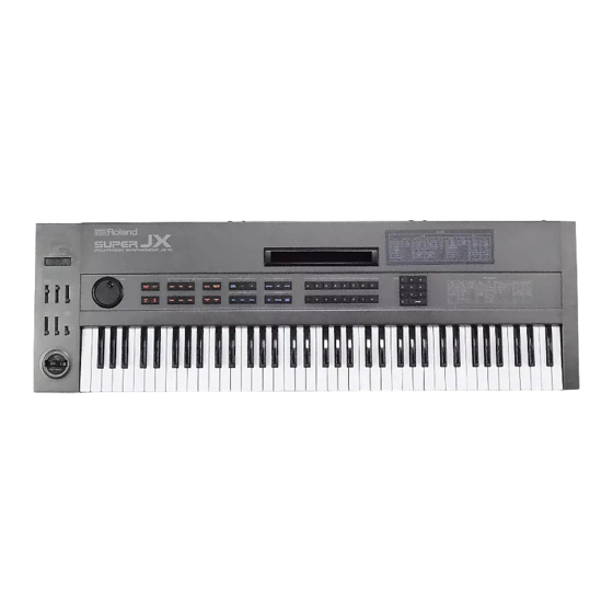
SPECIFICATIONS Roland JX-10 (Produced from 1986-1989) The JX-10: 12 Voice Polyphonic Synthesizer Rear Panel with Dynamics and Aftertouch Mixed Output Jack Keyboard: 76 keys Parallel Output Jack x 4 Headphones Jack Memory: Output Level Switch Patch Memory Hold Pedal Jack... - Page 58 UPPER/LOWER PORTAMENTO 36, 46 UPPER/LOWER HOLD 37, 47 UPPER/LOWER VOLUME 1. Sending the Program Change to the MIDI Sound Module by changing Patch Memories on the JX-10. MIDI OUT MIDI JX-10 Sound module MIDI IN • MIDI Setting on the MIDI Sound Module MIDI CHANNEL ........
- Page 59 3. Sending two different Program Change numbers separately to two MIDI Sound Modules by changing Patch Memories on the JX-10. MIDI THRU M I D I S o u n d m o d u l e 1...
- Page 60 In this setting, if the factors 61 and 62, “MIDI CH SEND” of a Patch Memory are set separately from the value 1 to 16, the transmitting MIDI Channels of the JX-10 are selected regardless of the Upper and Lower Channels which are set in Factors 13 and 14 (Upper/Lower Channel Send) in the MIDI functions section.
- Page 61 [31 UP PROGRAM CHANGE....OFF] [14 LOWER MIDI CH ........1] [41 LO PROGRAM CHANGE....OFF] In this setting, Patch Memories of the JX-10 are changed by the Program Change messages transmitted from the external MIDI Keyboard. Program Change number which is Patch Memory of the JX-10 transmitted to the JX-10’s MIDI IN...
-
Page 62: Midi Function
7. Relation between Key Mode of the JX-10 and MIDI CH (receiving) When using the JX-10 as MIDI Sound Module, the receiving MIDI Channels are set only in Factors 13 and 14 “MIDI CH”. The Patch Memory Factor 17, “KEY MODE” (located in the Patch parameter section), determines which channel will be selected;... - Page 63 Extra JX-10 options with Firmware version 3.14 (or 4.08) The JX-10 also gets the extra (8 ) parameter with this version. On the JX-10, however, there are a few more options: KEYBOARD, MIDI, ALL, KEYB+OUT, MIDI+OUT, ALL+OUT. “Where the notes are taken from”...
- Page 64 The current released versions are described here, with a list of changes. Note: If any erratic behaviour is noticed after an upgrade it’s likely that you didn’t perform the RESET procedure. See page 40 for instructions. "Roland" version (standard electronics – program ROM change only) 3.00 • Initial release.
- Page 65 3.09 • Bug fix: in some circumstances, the arpeggiator could have a stuck note (only in legato mode). 3.10 • Bug fix (JX10 only) : patch parameter "MIDI key mode", when mode is UPPER or LOWER, is considered as LAYER. 3.11 •...
- Page 66 4.07 • The Roland PULS (now used to create real PWM) is back! If you set PWM WIDTH to 00, the old Roland method of generating a pulse (by overdriving the ramp generator) is used, instead of the pwm daughter board.
- Page 67 ROLAND – VECOVEN MIDI ASSIGNMENT CHANGES Original Roland MIDI parameter assignment numbers are different to those in Vecoven Firmware. The following charts show the new assignments: Vecoven Firmware 3.07 Roland Original JX-10 Parameter MIDI Parameter No: MIDI Parameter No: Upper Local...
- Page 68 Section 8 - SUPER Sound Charts BACK and ELECTRIC PIANO 1 VOICES AFRICAN MALLET IS THIS FAT BREATHING BRASS LOW STRINGS PAD DCO WAVE 1 FORTH CHASE 83 PIANO 4 49 BACK-SAW VOICES HISS 27 MARIMBA B 74 GOWESTBRS2 HORNZ 1 88 STRINGS 1 14 WAVEOLA 2 39 HARMO 1...
- Page 69 HORNS 1 HORNS 2 MELLOW BRS FAT FIFTH SAXOPHONES S/BRASS A S/BRASS B R/STRINGS A R/STRINGS B VOICES A VOICES HISS PAD 1 WAVEOLA 1 WAVEOLA 2 WAVEOLA 3 RASPWAVE 1 TOUCH POLY SYNTH LEAD 1 SYNC SOLO 1 E/PIANO 1 PIANO 1-A PIANO 1-B VIBISH A...
- Page 70 Without help from contributors and beta testers, this manual would never have been written. It is an important document and we hope that everyone gets maximum use from it. The JX-10 MIDI implementation has been completely re-written following great work done by Fred Vecoven (http://www.vecoven.com) to bring the JX-10 operationally where it deserves to be.
- Page 71 Hold Pedal Jack MIDI Connectors (In/Out/Thru) Programmer Connector Internal Memory Protect Switch Control Assign Jack Section 3 Outline of JX-10 Functions Patch Memory Description Patch Memory Factors Patch Memory Tone Writing Edited Patch Memory Using a Memory cartridge Sequencer vs. Arpeggiator...
- Page 72 1 - Save Single PM to Cartridge 5.0b 2 - Load Single PM to JX-10 5.0c Copying a Tone 5.0c 1 - Save a Tone to Cartridge 5.0c 2 - Copy Tone from Cartridge to JX-10 Manual Version 3.21 Page. 72 of 73...
- Page 73 MIDI Volume Control 7.0a System Exclusive ON/OFF 7.0b MIDI Functions for Patch Memory 7.0b MIDI MENU (FACTORS) 7.0c MIDI JX-10 Implementation Charts 7.0c 1 - Transmitted Data 7.0c 2 - Recognised Receive Data 7.0c 3 - System Exclusive Messages 7.0c Individual Patch Parameters 7.0c...