Table of Contents
Advertisement
Quick Links
Advertisement
Chapters
Table of Contents

Related Manuals for HYOSUNG RT125D


Summary of Contents for HYOSUNG RT125D
- Page 1 SERVICE MANUAL...
- Page 2 SERVICING INFORMATION * This manual is intended for those who have enough knowledge and skills for servicing HYOSUNG vehicles. Without such knowledge and skills, you should not attempt servicing by relying on this manual only. Instead, please contact your nearby authorized HYOSUNG motorcycle dealer.
-
Page 3: How To Use This Manual
HOW TO USE THIS MANUAL TO LOCATE WHAT YOU ARE LOOKING FOR: 1. The text of this manual is divided into sections. 2. As the title of these sections are listed on the previous page as GROUP INDEX, select the section where what you are looking for belong. - Page 4 SYMBOL Listed in the table below are the symbols indicating instructions and other information necessary for servicing and mean- ing associated with them respectively. SYMBOL DEFINITION SYMBOL DEFINITION Torque control required. Apply THREAD LOCK Data beside it indicates specified torque. Apply oil.
-
Page 5: Table Of Contents
GENERAL INFORMATION CONTENTS INFORMATION LABELS GENERAL PRECAUTIONS SERIAL NUMBER LOCATION FUEL AND OIL RECOMMENDATIONS BREAK-IN PROCEDURES EXTERIOR ILLUSTRATION SPECIFICATIONS... -
Page 6: General Precautions
GENERAL INFORMATION WARNING / CAUTION / NOTE Please read this manual and follow its instructions carefully. To emphasize special information, the symbol and the words WARNING, CAUTION and NOTE have special meanings. Pay special attention to the messages highlighted by these sig- nal words. - Page 7 GNERAL INFORMATION CAUTION If parts replacement is necessary, replace the parts with HYOSUNG Genuine Parts or their equivalent. When removing parts that are to be reused, keep them arranged in an orderly manner so that they may be reinstalled in the proper order and orientation.
- Page 8 GENERAL INFORMATION HYOSUNG NOTE Difference between photographs and actual motorcycles depends on the markets.
-
Page 9: Serial Number Location
GENERAL INFORMAION SERIAL NUMBER LOCATION The frame serial number or V.I.N. (Vehicle Identification Number) is stamped on the steering head tube. The engine seri- al number is located on the left upside of crankcase assembly. These numbers are required especially for registering the machine and ordering spare parts. FRAME SERIAL NUMBER ENGINE SERIAL NUMBER... -
Page 10: Fuel And Oil Recommendations
GENERAL INFORMATION FUEL AND OIL RECOMMENDATION FUEL Gasoline used should be graded 85 95 octane (Research Method) or higher. An unleaded gasoline type is recommend- ENGINE OIL ENGINE OIL SPECIFICATION Classification system Grade Over SG 10W/30 or 10W/40 If an SAE 10W/30 or 10W/40 motor oil is not avail- able, select an alternative according to the fol- lowing chart. -
Page 11: Break-In Procedures
GENERAL INFORMAION BREAK-IN PROCEDURES During manufacture only the best possible materials are used and all machined parts are finished to a very high standard but it is still necessary to allow the moving parts to BREAK-IN before subjecting the engine to maximum stresses. The future performance and reliability of the engine depends on the care and restraint exercised during its early life. -
Page 12: Exterior Illustration
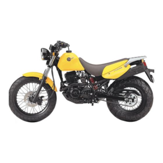
GENERAL INFORMATION EXTERIOR ILLUSTRATION Turn sigmal lamp(Rear) Tail/Brake lamp License plate lamp Rear reflector Turn signal lamp ( Front ) Head lamp Passenger footrests ( WHEEL BASE ) ( LENGTH ) -
Page 13: Specifications
GENERAL INFORMAION SPECIFICATIONS DIMENSIONS AND DRY MASS Overall length ................2,085 mm (82.1 in) Overall width ................840 mm (33.1 in) Overall height ................1,125 mm (44.3 in) Wheelbase ................1,350 mm (53.2 in) Ground clearance ..............230 mm (9.1 in) Mass .................. - Page 14 GENERAL INFORMATION ELECTRICAL Ignition type ................Battery Ignition (CDI) Ignition timing ................15 B.T.D.C.at 2,250 rpm and 31 B.T.D.C.at 4,000 rpm Spark plug ................. C8EH-9 Battery ..................12V 6Ah Fuse ..................15 A Head lamp .................. HI : 35W LO : 35W Turn signal lamp ...............
- Page 15 PERIODIC MAINTENANCE CONTENTS PERIODIC MAINTENANCE SCHEDULE MAINTENANCE PROCEDURES BATTERY CYLINDER HEAD NUTS, CYLINDER NUTS, EXHAUST PIPE NUTS AND MUFFLER MOUNTING BOLTS AIR CLEANER ELEMENT VALVE CLEARANCE SPARK PLUG FUEL LINE ENGINE OIL ENGINE OIL FILTER CARBURETOR 2-10 CLUTCH 2-11 DRIVE CHAIN 2-12 BRAKES 2-14...
-
Page 16: Periodic Maintenance Schedule
PERIODIC MAINTENANCE PERIODIC MAINTENANCE SCHEDULE The chart below lists the recommended intervals for all the required periodic service work necessary to keep the motorcy- cle operating at peak performance and economy. PERIODIC MAINTENANCE CHART ENGINE Interval Every 8,000 km Initial 1,000 km Every 4,000 km page Item... - Page 17 PERIODIC MAINTENANCE LUBRICATION POINT Proper lubrication is important for smooth operation and long life of each working part of the motorcycle. Major lubrication points are indicated below. Clutch lever holder Front brake lever holder Drive chain Throttle cable Side stand pivot and spring hook Rear brake pedal pivot Speedometer gear box - Motor oil,...
-
Page 18: Maintenance Procedures
PERIODIC MAINTENANCE MAINTENANCE PROCEDURE This section describes the service procedures for each section of the periodic maintenance. BATTERY Inspect Interval Inspect Initial 1,000 km and Every 4,000 km. Remove the right frame cover for measure of battery voltage. Using pocket tester, measure the battery voltage. If the tester reading is less than 12.8V, recharge bat- tery by a battery charger. -
Page 19: Engine
PERIODIC MAINTENANCE CYLINDER HEAD NUTS AND CYLINDER NUTS Remove the seat and fuel tank. (Refer to page 3-1) Remove the cylinder head cover. Tighten the four 8 mm nuts and four 16 mm nuts to the specified torque with a torque wrench, when engine is cold. -
Page 20: Air Cleaner Element
: do not twist or wring the element or it will develop tears. Immerse the element in Hyosung genuine oil , and squeeze the oil out of the element leaving it slightly wet with oil. -
Page 21: Valve Clearance
PERIODIC MAINTENANCE VALVE CLEARANCE Inspect Interval Inspect lnitial 1,000 km and Every 4,000 km. Excessive valve clearance results in valve noise and insufficient valve clearance results in valve damage and reduced power. At the distances indicated above, check and adjust the clearance to the following specification. The procedure for adjusting the valve clearance is as follows : Remove the seat and fuel tank. -
Page 22: Spark Plug
PERIODIC MAINTENANCE SPARK PLUG Inspect Interval Clean Initial 1,000 km and Every 4,000 km, Replace Every 8,000 km. Disconnect the spark plug caps. Remove the spark plugs. TYPE SPARK PLUG SPECIFICATION Hot type C7EH-9 Standard type C8EH-9 Cold type C9EH-9 Remove the carbon deposite with wire or pin and adjust the spark plug gap to 0.8 0.9 mm, measuring with a thickness gauge. -
Page 23: Fuel Line
PERIODIC MAINTENANCE FUEL LINE Inspect Interval Inspect lintial 1,000 km and Every 4,000 km, Replace every four years. Inspect the fuel line and connections for damage and fuel leakage. If any defects are found, the fuel line must be replaced. ENGINE OIL Inspect Interval Replace lintial 1,000 km and Every 4,000 km. -
Page 24: Engine Oil Filter
PERIODIC MAINTENANCE CAUTION Never operate the motorcycle if the engine oil level is below the Lower line mark(L) in the engine oil level gauge. Never fill the engine oil above the Upper line mark(F) . Engine oil level being most suitable about 1mm under the Upper line mark(F) of the engine oil level gauge. -
Page 25: Carburetor
TER only, since the other make s genuine filters and after-market parts may differ filtering perfor- mance and durability, which could cause engine damage or oil leaks. Hyosung motors genuine oil filter is also not usable for the motocycles. CARBURETOR Inspect Interval Inspect lintial 1,000 km and Every 4,000 km. -
Page 26: Clutch
PERIODIC MAINTENANCE 2-11 THROTTLE CABLE PLAY There should be 0.5 1.0 mm play on the throttle cable. To adjust the throttle cable play. Tug on the throttle cable to check the amount of play. Loosen the lock nut and turn the adjuster in or out until the specified play is obtained. -
Page 27: Drive Chain
PERIODIC MAINTENANCE 2-12 DRIVE CHAIN Inspect Interval Clean and Lubricate Every 1,000 km. Visually check the drive chain for the possible defects listed below. (Support the motorcycle by the jack or block, turn the rear wheel slowly by hand with the trans- mission shifted to Neutral.) Loose pins Excessive wear... - Page 28 PERIODIC MAINTENANCE 2-13 Loosen or tighten both chain adjusters until the chain has 20 30 mm of slack in the middle between the engine and rear sprockets. The marks both chain adjusters must be at the same position on the scale to ensure that the front and rear wheels are correctly aligned.
-
Page 29: Brakes
PERIODIC MAINTENANCE 2-14 BRAKES Inspect Interval Inspect lnitial 1,000 km and Every 4,000 km, Replace the hoses Every four years, Replace the brake fluid Eevery two years. FRONT BRAKE Brake fluid level Upright position of the motorcycle, and place the han- dlebars straight. - Page 30 PERIODIC MAINTENANCE 2-15 AIR BLEEDING OF THE BRAKE FLUID CIRCUIT Air trapped in the brake fluid circuit acts like a cushion to absorb a large proportion of the pressure developed by the master cylinder and thus interferes with the full brak- ing performance of the brake caliper.
- Page 31 PERIODIC MAINTENANCE 2-16 REAR BRAKE REAR BRAKE ADJUSTING This is effected by turning the brake pedal stopper. Be sure to tighten the lock nut securely after setting the bolt. After adjusting the rear brake height, adjust the brake pedal traval, First set the pedal at position for comfort- able riding by turning the brake pedal stopper, and then adjust the free travel to 20~30 mm.
-
Page 32: Tires
180/80-14M/C 78P for rear. as follows. The use of tires other than those specified may cause instability. It is highly recommended to use SOLD RIDING DUAL RIDING COLD INFLATION a HYOSUNG Genuine Tire. TIRE PRESSURE kg/cm KPa kg/cm Front 1.25 18.0 1.50... -
Page 33: Rear Suspension
PERIODIC MAINTENANCE 2-18 REAR SUSPENSION Inspect Interval Inspect Every 4,000 km. Inspect the rear shock absorber for oil leakage and mounting rubbers including engine mounting for wear and damage. Replace any defective parts, if necessary. CHASSIS BOLTS AND NUTS Inspect Interval Tighten Initial 1,000 km and Every 4,000 km. -
Page 34: Compression Pressure
PERIODIC MAINTENANCE 2-19 COMPRESSION PRESSURE The compression of a cylinder is a good indicator of its internal condition. The decision to overhaul the cylinder is often based on the results of a compression test. Periodic maintenance records kept at your dealership should include compres- sion reading for each maintenance service. -
Page 35: Oil Pressure
PERIODIC MAINTENANCE 2-20 OIL PRESSURE Check the oil pressure periodically. This will give a good indication of the condition of the moving parts. Standard Oil pressure 0.3 0.5 (at 60 3,000 rpm) If the oil pressure is lower or higher than the specification, the following causes may be considered. LOW OIL PRESSURE Oil leakage from the oil passage Damaged O-ring... - Page 36 ENGINE CONTENTS ENGINE REMOVAL AND REMOUNTING ENGINE REMOVAL ENGINE REMOUNTING UPPER END COMPONENTS DISASSEMBLY UPPER END COMPONENTS INSPECTION AND SERVICING 3-10 UPPER END COMPONENTS REASSEMBLY 3-16 LEFT ENGINE DISASSEMBLY 3-22 RIGHT ENGINE DISASSEMBLY 3-23 LOWER END COMPONENTS DISASSEMBLY 3-26 LOWER END COMPONENTS INSPECTION AND SERVICING 3-29 LOWER END COMPONENTS REASSEMBLY 3-33...
- Page 37 ENGINE ENGINE REMOVAL AND REMOUNTING ENGINE REMOVAL The procedure of engine removal is sequentially explained in the following steps. NOTE If the engine is dirtied, wash the machine with a suitable cleaner before removing the engine. Take off the seat by loose two volts below seat. Disconnect the lead wires of battery CAUTION...
- Page 38 ENGINE Disconnect the lead wire of starter motor. Take off the spark plug cap. Disconnect the lead wire of magento. Take off the breather hose.
- Page 39 ENGINE Loosen the two clamp screws, bolt and take off the carburetor. Remove the engine sprocket cover. Take off the drive chain by removing the clip. Disconnect the ground wire from the crankcase. Take off the gear shift lever by removing the bolt.
- Page 40 ENGINE Remove the exhaust pipe nuts, muffler mounting bolts and exhaust pipe clamp bolt, then take off the muffler. Take out only one third of shaft after remove the swing arm pivot nut Remove engine mounting bolts After remove the swing arm pivot shaft, use both hands, and lift the engine from the frame.
- Page 41 ENGINE After remounting the engine, following adjustments ENGINE REMOUNTING are necessary. The engine can be mounted in the reverse order of removal. Throttle cable (Page : 2-11) Temporarily fasten the engine mounting bracket Clutch cable (Page : 2-11) before inserting the engine mounting bolts. Drive chain (Page : 2-12) Rear brake pedal...
- Page 42 ENGINE UPPER END COMPONENTS DISASSEMBLY CYLINDER HEAD COVER-CAMSHAFT CAUTION When removing the cylinder head cover, the pis- ton must be at top dead center on compression stroke. Remove the cam chain tensioner. Loosen the cylinder head cover bolts and detach the head cover.
- Page 43 ENGINE Remove the cam sprocket center bolt. CAUTION This is a left-hand thread nut. Remove the camshaft , cam sprocket and C-ring CAUTION Do not drop the camshaft drive chain, key and sprocket into the crankcase. Take off the rocker arm spring from the dowel pin Remove the dowel pin with the long-nose pliers.
- Page 44 ENGINE Install the bolt by the rocker arm shaft and pull out the rocker arm shaft. Remove the rocker arm and spring Remove the rocker arm shaft by the same manner at the opposite side. Loosen the cylinder head nuts, then detach the cylin- der head.
- Page 45 ENGINE Remove the oil seal, using the long-nose pliers. Take out the spring seat, valve guide. CAUTION Removed parts should be marked for install at the original position. Decarbonate in the combustion chamber. CYLINDER Remove the cylinder base nuts and cylinder. CAUTION If tapping with the plastic hammer is necessary, do not break the fins.
- Page 46 ENGINE 3-10 UPPER END COMPONENTS INSPECTION AND SERVICING CAMSHAFT HOLDER DISTORTION After removing the oil from the fitting surface of the camshaft holder, place the camshaft holder on a surface plate and check for distortion with a thickness gauge. Check points are shown in Fig. Service limit Camshaft holder distortion 0.05mm (0.002 in)
- Page 47 ENGINE 3-11 CAMSHAFT CAM WEAR Worn-down cams are often the cause of mistimed valve operation resulting in reduced output power. The limit of cam wear is specified for both intake and exhaust cams in terms of cam height , which is to be measured with a micrometer.
-
Page 48: Valve Spring
ENGINE 3-12 VALVE HEAD RADIAL RUNOUT Place a dial gauge as shown and measure valve head radial runout. If the service limit is exceeded, replace the valve. Service limit Valve head radial runout 0.03 mm (0.0012 in) Dial gauge : 09900-20606 Magnetic stand : 09900-20701 V-block : 09900-21304 VALVE GUIDE-VALVE STEM CLEAR-... - Page 49 ENGINE 3-13 Standard Valve spring tension 13.6~16.6 kgf (IN. & EX.) (29.98 36.60 lbs) at length 36.6 mm (1.44 in) CYLINDER DISTORTION Check the gasketed surface of the cylinder for distortion with a straightedge and thickness gauge, taking a clear- ance reading at several places as indicated.
- Page 50 ENGINE 3-14 PISTON-CYLINDER CLEARANCE As a result of the above measurement, if the piston to cylinder clearance exceeds the limit shown in the table below, overhaul the cylinder and use an oversize piston, or replace both cylinder and piston. Piston to Service limit cylinder clearance 0.120 mm (0.0047 in)
-
Page 51: Piston Ring End Gap Inspection
ENGINE 3-15 PISTON RING END GAP INSPECTION Insert the piston ring squarely into the cylinder using the piston head. Measure the end gap with a thickness gauge. If the gap exceeds the service limit, replace the piston ring. Standard Piston ring end gap(Assembling condition) 0.20~0.32 mm (0.0079 0.0126 in) 0.20~0.32 mm (0.0079 0.0126 in) Service limit... -
Page 52: Piston Ring
ENGINE 3-16 PISTON PIN HOLE BORE Using a dial calipers, measure the piston pin hole bore both in the vertical and horizontal directions. If the measurement exceeds the service limit, replace the piston. Service limit Piston pin hole bore 15.030 mm (0.5917 in) Dial calipers : 09900-20605 PISTON PIN DIAMETER INSPECTION Using a micrometer, measure the piston pin outside... - Page 53 ENGINE 3-17 PISTON The following are reminders for piston installation: Rub a small quantity of MOLY PASTE onto the piston pin. MOLY PASTE Place a clean rag over the cylinder base to prevent piston pin circlip from dropping into crankcase, and then fit the piston pin circlip with long-nose pliers.
- Page 54 ENGINE 3-18 VALVE AND SPRING Insert the valves, with their stems coated with ( MOLY PASTE) all around and along the full stem length without any break. Similarly oil the lip of the stem seal. MOLY PASTE CAUTION When inserting each valve, take care not to dam- age the lip of the stem seal.
- Page 55 ENGINE 3-19 CAMSHAFT Align the mark on magneto rotor with the index mark on the crankcase keeping the camshaft drive chain pulled upward. CAUTION If crankshaft is turned without drawing the camshaft drive chain upward, the chain will be caught between crankcase and cam chain drive sprocket.
- Page 56 ENGINE 3-20 CAMSHAFT HOLD Apply HYOSUNG MOLY PASTE to the rocker arm shafts then inserting the camshaft hold. Install the rocker arm spring rocker arm inserting the camshaft hold CAUTION Pay attention to the exhaust side rocker arm that have not confused, the groove at the intake side Groove rocker arm so that avoid contact with stud bolt.
-
Page 57: Chain Tensioner
ENGINE 3-21 Tighten the camshaft holder nuts diagonally to the specified. Camshaft holder nut : 15~20 N m (1.5~2.0 kg m) CHAIN TENSIONER Mount the tensioner body on the cylinder. Install the spring and bolts. VALVE CLEARANCE After tightening the camshaft holder lock nuts, check and adjust the valve clearance. -
Page 58: Cylinder Head Cover
ENGINE 3-22 CYLINDER HEAD COVER Clean off oil from the surfaces of cylinder head and cover. Fit the packing to the cylinder head cover Tighten the cylinder head cover bolts with the hexagon wrench. Cylinder head cover : 9~10 N m (0.9~1.0 kg m) LEFT ENGINE DISASSEMBLY Remove the magneto rotor and key. - Page 59 ENGINE 3-23 Remove the roller , spring and push piece from the starter clutch. Clamp the rotor with a vise taking care not to damage it and remove the three bolts using the 5 mm T type hexagon wrench. GEAR POSITION SWITCH Remove the gear position indicator switch by remov- ing the screws.
- Page 60 ENGINE 3-24 CLUTCH Remove the kick starter by removing the bolt. Remove the clutch cover bolts and oil filter cap bolts, and detach the clutch cover by tapping with a plastic hammer. Remove the clutch spring mounting bolts diagonally while holding the primary driven gear, and remove the clutch pressure plate.
- Page 61 ENGINE 3-25 OIL PUMP DRIVE GEAR, DRIVEN GEAR AND PRIMARY DRIVE GEAR Flatten the lock washer, then remove the nut, lock washer and oil pump drive gear. Conrod holder : 09910-20115 CAUTION This is a left-hand thread nut. Remove the oil pump driven gear, then remove the primary drive gear and key.
- Page 62 ENGINE 3-26 KICK STARTER DRIVE GEAR AND IDLE GEAR Remove the kick starter drive gear and kick starter idle gear. LOW END COMPONENTS DISASSEMBLY CRANK CASE Remove the sump filter cap and cam stopper plug Pull out the spring, neutral stopper. Remove the sump filter.
- Page 63 ENGINE 3-27 Separate the crankcase into 2 part, right and left with the crankcase separater. Fit the crankcase separater so that the tool plate is parallel with the end face of the crankcase. Crankcase separater : 09920-13120 CAUTION The crankshaft and transmission components must remain in the left crankcase half.
- Page 64 ENGINE 3-28 KICK STARTER SHAFT Remove the circlip, spring guide and return spring. Then, pull out the kick starter shaft from the other side. CRANKSHAFT Remove the crankshaft by using the crankcase sepa- rater. Crankcase separater : 09920-13120 OIL SEAL AND BEARING Remove the retainer, oil seals and bearings, right and left.
- Page 65 ENGINE 3-29 LOWER END COMPONENTS INSPECTION AND SERVICING CONROD SMALL END INSIDE DIAM- ETER INSPECTION Using a dial calipers, measure the conrod small end inside diameter both in vertical and horizontal directions. If any of the measurements exceeds the service limit, replace the conrod.
- Page 66 ENGINE 3-30 CLUTCH DRIVE PLATE Measure the thickness and claw width of each drive plate with vernier calipers. Replace the drive plates found to have worn down to the limit. Vernier calipers : 09900-20101 Standard Thickness of clutch drive plate 2.9 3.1 mm Checking thickness (0.1142 0.1220 in)
- Page 67 ENGINE 3-31 CLUTCH RELEASE BEARING Inspect the clutch release bearing for any abnormality, especially cracks. When removing the bearing from the clutch, decide whether it can be reused or if it should be replaced. Smooth engagement and disengagement of the clutch depends on the condition of this bearing.
- Page 68 ENGINE 3-32 PRIMARY DRIVEN GEAR Inspect the primary driven gear bearing for any damage. If any abnormal condition are found, replace the primary driven gear. CAM CHAIN 20-PITCH LENGTH Pull the chain tight to remove any slack, then using vernier caliper, measure the 20-pitch (21 pins) length of cam chain.
- Page 69 ENGINE 3-33 LOWER END COMPONENTS REASSEMBLY CRANKSHAFT Inspect the between the webs referring to the below When mounting the crankshaft in the crankcase, it is figure when rebuilding the crankshaft. necessary to pull its left end into the crankcase. Standard Crankcase installer : 09910-32812 Conrod holder : 09910-20115 53.0 0.1mm...
- Page 70 ENGINE 3-34 CAUTION Never fit the crankshaft into the crankcase by striking it with a plastic hammer. Always use the special tool, otherwise crankshaft alignment accuracy will be affected. TRANSMISSION CAUTION Never reuse a circlip. After a circlip has been removed from a shaft, it should be discarded and a new circlip must be installed.
- Page 71 ENGINE 3-35 Washers and circlips thickness NOTE When reassembling the bearing retainer, apply a small quantity of THREAD LOCK 1324 to the threaded parts of the bearing retainer screws. In reassembling the transmission, attention must be given to the locations and positions of washers and cir- clips.
- Page 72 ENGINE 3-36 GEAR SHIFTING CAM AND FORK Fit the gear shifting cam on the crankcase. Position the cam as shown in Fig. So that the gear shifting fork can be installed easily.
- Page 73 ENGINE 3-37 CAUTION Two kinds of the gear shifting forks, are used. They resembles each other very closely in external appearance and configuration. Carefully examine the illustration for correct installing positions and directions. After the cam stopper and gear shifting forks have been fitted, hook the cam stopper spring into the crankcase.
- Page 74 ENGINE 3-38 When fitting the kick starter to the shaft, be sure to align the punched marks.. Fit the spring and washer on the shaft. Then, insert the kick starter shaft into the crankcase. Engage the pawl of kick starter guide When fitting the kick return spring, hook the part return spring into the crankcase, turn it 1/2 a turn clockwise with the pliers and fit the part...
- Page 75 ENGINE 3-39 After the crankcase bolts have been tightened, check if the driveshaft and countershaft rotate smoothly. If a large resistance is felt to rotation, try to free the shafts by tapping the driveshaft or countershaft with a plastic hammer as shown in Fig. RIGHT ENGINE REASSEMBLY KICK START DRIVE GEAR AND IDLE GEAR...
- Page 76 ENGINE 3-40 GAER SHIFTING SHAFT Install the gear shifting shaft. Match the center teeth of the gear on the shifting shaft with the center teeth on the shifting driven gear as shown. CAUTION After the cam driven gear, cam guide, gear shifting shaft and neutral cam stopper have been fitted, confirm that gear change is nor- mal while turning, the countshaft and drive-...
- Page 77 ENGINE 3-41 Fit the oil pump driven gear and install the cir- clip CAUTION After mounting the oil pump in the crankcase, rotate the pump gear by hand to see if it turns smoothy. After checking the oil pump, install the oil pump drive gear, lock washer and nut, tighten it with a torque wrench to the specified torque and bend up to the washer.
- Page 78 ENGINE 3-42 Install the clutch camshaft by positioning the face to right side. Install the oill seal by using the 17 mm socket. Tighten the oil seal retainer screw. Assemble the clutch, in the reverse order of disassem- bly. Pay attention to the following points. When inserting the spacer on the countershaft, apply a small quantity of engine oil to both inside and out- side of the spacer.
- Page 79 ENGINE 3-43 Tighten the clutch spring bolts diagonally. Clutch release screw adjustment Loosen the lock nut, and turn in the release screw to feel high resistance. From that position, turn out the release screw 1/4-1/2 turn, and tighten the lock nut. Clutch cover bolt : 8 12N m (0.8 1.2kg m) Oil filter cap bolt...
-
Page 80: Magneto Rotor
ENGINE 3-44 STATOR Apply a small quantity of THREAD LOCK 1324 to the threaded parts of screws. Thread Lock 1324 STARTER CLUTCH Locate the shim to the proper position Install the roller, spring and push piece to the starter clutch. Apply THREAD LOCK 1324 to the bolts and tight- en with the specified torque. - Page 81 ENGINE 3-45 Tighten the magneto rotor nut to the specified torque. Thread Lock 1324 Rotor holder : 09930-40113 Rotor holder : 09930-44511 Magneto rotor nut : 30~40 N m (3.0~4.0 kg m) STARTER IDLE GEAR AND MOTOR Install the starter idle gear. Install the starter motor.
- Page 82 ENGINE 3-46 Tighten the engine sprocket nut to the specified torque and bend up the washer. Rotor holder : 09930-40113 Engine sprocket nut : 80~100 N m (8.0~10.0 kg m) GEAR POSITION SWITCH Install the gear position switch.
-
Page 83: Fuel System
FUEL SYSTEM CONTENTS FUEL COCK REMOVAL CLEANING REMOUNTING CARBURETOR THROTTLE VALVE CARBURETOR... -
Page 84: Fuel Cock
FUEL SYSTEM FUEL COCK REMOVAL Turn the fuel cock to OFF position and disconnect the fuel hose from the fuel cock. Place a clean oil pan under the fuel cock assembly, turn the fuel cock to RES position and drain the fuel. -
Page 85: Carburetor
FUEL SYSTEM CARBURETOR ITEM SPECIFICATION ITEM SPECIFICATION Carburetor type Needle jet (N.J) PD 18 F Bore size Pilot jet (P.J) I.D. NO. By pass (B.P.) RT125 Idel rpm Pilot air jet (P.A.J) 1,450 50rpm Jet needle (J.N.) Valve seat (V.S.) AIFC-2 Float height Starter jet... -
Page 86: Throttle Valve
FUEL SYSTEM THROTTLE VALVE Disconnect the seat and fuel tank. (See page 3-1) Looen the carburetor top and disconnect the throt- tle valve. Remove the throttle cable from the throttle valve and disconnect the throttle cable. Disconnect the throttle valve spring and carburetor top from the throttle cable. -
Page 87: Carburetor
FUEL SYSTEM Install the jet needle and retainer clip into the throttle valve. Needle clip standard position : 3rd groove Install the carburetor top and spring into the throttle cable. Install the throttle cable into the throttle valve. Following adjustments and inspection are necessary after installing the throttle valve. - Page 88 FUEL SYSTEM Loosen the carburetor nut and clamp screw. Remove the carburetor. Disconnect the fuel tube and drain tube. ACCELERATOR PUMP Loosen the screws and disconnect the pump cover. Disconnect the spring of pump diaphragm. Inspect the accelerator pump load damage of the diaphragm.
- Page 89 FUEL SYSTEM Set up the diaphragm and the float chamber. Install the spring in the pump cover and install the cover in the float chamber. Adjust the accelerator pump. FLOAT AND NEEDLE VALVE Loosen the screws and remove the float chamber. Pull out the float arm pin.
- Page 90 FUEL SYSTEM JETS Disconnect the main jet , needle jet holder needle jet. Disconnect the pilot jet Disconnect the pilot screw recording the revolu- tions until tighten completely. CAUTION Do not tighten the pilot screw by force, otherwise can be damaged of the seat. Disconnect the throttle stop screw Clean the jets with non-flammable cleaning solvent.
- Page 91 FUEL SYSTEM Install the needle valve , float float arm pin FLOAT ADJUSTMENT To check the float height, invert the carburetor body, holding the float arm pin so that the pin will not slip off. Float height 12.5 mm (0.492 in) Vernier calipers : 09900-20101 Check to be sure that the float moves freely.
-
Page 92: Pilot Screw Adjustment
FUEL SYSTEM REASSEMBLY Install the fuel tube and drain tube. Replace a new O-ring at the carburetor outlet side. Install the carburetor between the intake pipe and air cleaner outlet tube, tighten the carburetor lock nut and clamp screw. Connect the choke cable and throttle cable. Adjust the choke cable. -
Page 93: Electrical System
ELECTRICAL SYSTEM CONTENTS IGNITION SYSTEM CHARGING SYSTEM STARTER SYSTEM SWITCHES 5-10 LAMP 5-11 BATTERY 5-13... -
Page 94: Ignition System
ELECTRICAL SYSTEM IGNITION SYSTEM is started as the battery discharged ignition system without a contact point. The battery ignition system is composed of a rotor tip, the D.C CDI, the igniton coil and battery. This system ignites after get signal from ignition timing of pick-up with the electric energy of this battery and occur the 1st electric current. - Page 95 ELECTRICAL SYSTEM INSPECTION MAGNETO Using the pocket tester, measure the resistance between the lead wires in the following table. Pick-up coil G-L Approx 90~110 Charging coil Y-Y Approx 0.6~0.9 Pocket Tester : 09900-25002 CAUTION When mounting the stator on the magneto cover, apply a small quantity of THREAD LOCK 1324 to the threaded parts of screws.
-
Page 96: Spark Plug
ELECTRICAL SYSTEM IGNITION COIL Pull out the spark plug. Place it on the cylinder head after installing it at the plug cap to obtain ground. Push in the electric starter switch to rotate the starter motor, to have the test of sparking performance. If not emited spark or the spark bring out the orange color, replace the ignition coil. -
Page 97: Charging System
ELECTRICAL SYSTEM CHARGING SYSTEM The circuit of the charging system is indicated in figure, which is composed of and the AC generator, regulator / rectifier unit and battery. The AC current generated from the AC generator is converted by the rectifier and is turned into the DC current, then it charges the battery. - Page 98 ELECTRICAL SYSTEM When the engine rpm become higher, the generated voltage of the AC generator also becomes higher and the voltage between points of the regulator according becomes high, and when it reaches the adjusted voltage of the con- trol unit, consequently the control unit becomes ON condition. On the ON condition of the control unit, signal will be sent to the SCR (Thyristor) gate probe and SCR will become ON condition.
- Page 99 ELECTRICAL SYSTEM INSPECTION CHARGING OUTPUT CHECK Start the engine and keep it running at 5,000 rpm. Using the pocket tester, measure the DC voltage between the battery terminal If the tester reads under 14.0 V or over 15.0 V, check the magneto no-load performance and regulator / rectifi- CAUTION When making this test, be sure that the bat-...
- Page 100 ELECTRICAL SYSTEM REGULATOR / RECTIFIER Disconnect the coupler. Using the multi-tester ( range), measure the resistance between the terminals in the following table. If the resistance checked is incorrect, replace the regu- lator / rectifier. Unit : Probe of tester 30 55 0.8 2 0.8 2...
-
Page 101: Starter System
ELECTRICAL SYSTEM STARTER SYSTEM The starter system is shown in the diagram below : namely, the starter motor, relay, IG switch, starter button and battery. Depressing the starter button (on the right handlebar switch box) energizes the relay, causing the contact points to close which connects the starter motor to the battery. -
Page 102: Starter Motor Inspection
ELECTRICAL SYSTEM STARTER MOTOR INSPECTION CARBON BRUSH Inspect the brushes for abnormal wear, crack or smoothness in the brush holder. If the brush has failed, replace the brush sub assy. COMMUTATOR Inspect the commutator for discoloration, abnormal wear or undercut Segment If the commutator is abnomally worn, replace the arma- ture. -
Page 103: Switches
ELECTRICAL SYSTEM 5-10 Apply SUPER GREASE A to the O-ring remount the starter motor. SUPER GREASE A SWITCHES Measure each switch for continuity using a tester. If any abnormality is found, replace the respective switch assemblies with new ones. Pocket tester : 09900 - 25002 IGNITION SWITCH ENGINE STOP SWITCH LOCK... -
Page 104: Lamp
ELECTRICAL SYSTEM 5-11 LAMP HEADLAMP TURN SIGNAL LAMP TAIL / BRAKE LAMP... -
Page 105: Combination Meter
ELECTRICAL SYSTEM 5-12 COMBINATION METER Remove the combination meter. Disassemble the combination meter as shown in the illustration. INSPECTION Using the pocket tester, check the continuity between lead wires in the following illustration. If the continuity measured incorrect, replace the respec- tive part. -
Page 106: Battery
ELECTRICAL SYSTEM 5-13 BATTERY CAUTION OF BATTERY TREATMENT The battery needs attention generally as it occur flammability gas. If does not, it should be explosion and severe accident. Pay attention to the following points. Prohibit positively that come in contact with short, spark or firearms. The battery recharge where be well-ventilated wide place. - Page 107 ELECTRICAL SYSTEM 5-14 Seal Pouring in battery electrolyte When insert the nozzles of the electrolyte container into the battery s electrolyte filler holes, holding the container firmly so that it does not fall. Take precaution not to allow any fluid to spill. CAUTION The pouring of electrolyte may not be done if the electrolyte container is pushed slopely.
-
Page 108: Recharging Operation
ELECTRICAL SYSTEM 5-15 Separation of electrolyte container. After confirming that the electrolyte has entered the bat- tery completely, remove the electrolyte containers from the battery. CAUTION Draw out slowly otherwise in case of remain elec- trolyte vaporize. Insert of the caps Insert the cap into the filler holes, pressing in firmly so that the top of the caps do not protrude above the upper surface of the battery s top cover. - Page 109 CHASSIS CONTENTS FRONT WHEEL FRONT BRAKE FRONT FORK 6-12 STEERING STEM 6-18 REAR WHEEL AND REAR BRAKE 6-22 REAR SOCK ABSORBER 6-27 SWING ARM 6-28...
-
Page 110: Front Wheel
CHASSIS FRONT WHEEL REMOVAL Support the machine by jack, block. Disconnect the speedometer cable. - Page 111 CHASSIS Disconnect the clamp. Remove the brake hose. Pull out the front fork clamp bolt and remove the front axle Draw out the front axle and take off the front wheel. DISASSEMBLY FRONT WHEEL Remove the front brake disk. Remove the wheel bearing by using the special tool. Wheel bearing remover : 09941 - 50111 CAUTION The removed bearing should be replaced with...
- Page 112 CHASSIS INSPECTION WHEEL BEARING Inspect the play of the wheel bearings by finger while they are in the wheel. Rotate the inner race by finger to inspect for abnormal noise and smooth rotation. Replace the bearing according to in the following proce- dure if there is anything unusual.
- Page 113 CHASSIS BRAKE DISC Make sure that the brake disc is clean and free of any greasy matter. Apply THREAD LOCK 1324 to the disc mounting bolts and tighten them to the specified torque. THREAD LOCK 1324 Brake disc bolt : 18~28 N m (1.8 ~2.8 kg m)
-
Page 114: Front Brake
CHASSIS FRONT BRAKE... -
Page 115: Brake Pad Replacement
CHASSIS BRAKE PAD REPLACEMENT Remove the caliper mounting bolts and take off the caliper. CAUTION Do not operate the brake lever while dismounting the caliper. Push the piston and caliper holder all the way to the caliper when removing the pad. Remove the pad. - Page 116 CHASSIS CALIPER REMOVAL AND DISASSEMBLY Disconnect the brake hose from the caliper and catch the brake fluid in a suitable receptacle. CAUTION Do not allow brake fluid to contact the paint sur- face, plastic or rubber parts, or its chemical reac- tion can cause discoloration or crack.
-
Page 117: Caliper Inspection
CHASSIS CALIPER INSPECTION Inspect the caliper cylinder wall and piston surface for scratch, corrosion or other damages. If any abnormal condition is noted, replace the caliper. Inspect the each rubber part for damage and wear. BRAKE DISC INSPECTION Check the brake disc for damage or cracks. Measure the thickness using the micrometer. - Page 118 CHASSIS Apply the silicone grease to the caliper holder. Silicone grease. TIGHTENING TORQUE Front brake hose union bolt : 20 25 N m (2.0 2.5 kg m) Front brake caliper mounting bolt : 18 28 N m (1.8 2.8 kg m) WARNING Bleed the air from brake fluid circuit after reassembling the caliper.
-
Page 119: Master Cylinder Inspection
CHASSIS 6-10 Remove the two fitting screws and separate the cap and diaphragm. Detach the dust seal boot and remove the circlip. Pull out the piston/cup set and spring MASTER CYLINDER INSPECTION Inspect the master cylinder bore for any scratches or other damage. - Page 120 CHASSIS 6-11 When remounting the master cylinder to the handle- Master Cylinder bars, first tighten the clamp bolts for upside as shown. WARNING Bleed air from the brake fluid circuit after reassembling master cylinder. (See page 2-15) Handlebar Clearance...
-
Page 121: Front Fork
CHASSIS 6-12 FRONT FORK... - Page 122 CHASSIS 6-13 DISASSEMBLY Remove the front wheel. (Refer to page 6-1) Remove the front fork after loosening the front fork upper and lower clamp bolts . NOTE Slightly loosen the front fork upper bolt facilitate next disassembly. Remove the front fender. Remove the front brake hose clamp and guide.
- Page 123 CHASSIS 6-14 With the damper rod held immovable, remove the damper rod bolt. Remove the damper rod and rebound spring from the inner tube. Remove the dust seal and oil seal stopper ring Separate the inner tube from the outer tube. INSPECTION FRONT FORK SPRING Measure the free length of the front fork spring...
- Page 124 CHASSIS 6-15 INNER TUBE AND OUTER TUBE Check the sliding of the inner tube, outer tube and damper rod ring for scratch, wear, bending, or other abnormal condition. REASSEMBLY Perform the reassembly and remounting work in the reverse order of the disassembly and removal proce- dures while observing the following instructions.
- Page 125 CHASSIS 6-16 Apply THREAD LOCK 1324 to the damper rod bolt With the damper rod held immovable, with the gasket fitted, tighten the damper rod bolt Front fork damper rod bolt : 30~40 N m (3.0~4.0 kg m) THREAD LOCK CAUTION Replace the gasket with a new one.
- Page 126 CHASSIS 6-17 Install the front fork to the motocycle. Align the upper surface of the inner tube with the upper surface of the steering stem upper bracket. Tighten the front fork lower clamp bolts and front fork upper bolts to the specified torque. Tighten the front fork upper clamp bolts to the specified torque.
-
Page 127: Steering Stem
CHASSIS 6-18 STEERING STEM... -
Page 128: Removal And Disassembly
CHASSIS 6-19 REMOVAL AND DISASSEMBLY Take off the front wheel. (See page 6-1) Take off the front fork. (See page 6-13) Remove the four bolts and front fender. Remove the handlebar clamp bolts. Remove the steering stem head bolt and take off the steering stem upper nut. - Page 129 CHASSIS 6-20 Remove the outer race fitted on the steering stem. This can be done with a chisel. Draw out the two inner races fitted to the top and bot- tem ends of the head pipe. INSPECTION Inspect and check the removed parts for the following abnormalities.
- Page 130 CHASSIS 6-21 Apply SUPER GREASE A to the upper bearing, lower bearing SUPER GREASE A STEERING STEM NUT Tighten the steering stem nut with the special tool. Clamp wrench : 09940-10122 Steering stem nut : 80~100 N m (8.0~10.0kg m) Turn the steering stem right and left, lock-to-lock, five or six times.
-
Page 131: Rear Wheel And Rear Brake
CHASSIS 6-22 REAR WHEEL AND REAR BRAKE REMOVAL Support the machine by jack or block. Pull out the cotter pin and remove the torque link nut and bolt. Remove the rear brake adjuster nut. - Page 132 CHASSIS 6-23 Remove the drive chain cover. Loosen the rear axle nut. Loosen the drive chain adjuster right and left. Disengage the drive chain from the rear sprocket. Draw out the axle shaft and take off the rear wheel. Separate the rear wheel from rear brake panel. DISASSEMBLY REAR WHEEL Flatten the washers and loosen the four nuts.
- Page 133 CHASSIS 6-24 Loosen the cam lever nut. Pull off the brake cam, washer, O-ring and cam lever. INSPECTION WHEEL AXLE : Refer to page 6-3 WHEEL : Refer to page 6-3 WHEEL BEARING : Refer to page 6-3 TIRE : Refer to page 2-17 SPROCKET Inspect the ’...
- Page 134 CHASSIS 6-25 BRAKE SHOE Check the brake shoes and decide whether it should be replaced or not from the thickness of the brake shoe lin- ings. CAUTION Replace the brake shoes as a set, otherwise brak- ing performance will be adversely affected. Service limit Thickness of brake shoe...
- Page 135 CHASSIS 6-26 BRAKE CAM LEVER Tighten the cam lever bolt with specified torque. Brake cam lever nut : 8~12 N m (0.8~1.2 kg m) CAUTION Adjust the rear brake pedal play after installation of the rear wheel.
-
Page 136: Rear Shock Absorber
CHASSIS 6-27 REAR SHOCK ABSORBER REMOVAL Remove the rear shock absorber by removing their nuts. INSPECTION Inspect the rear shock absorber for damage and oil leakage. If any defects are found, replace the rear shock absorber with a new one. CAUTION Do not attempt to disassemble the rear shock absorber. -
Page 137: Swingarm
CHASSIS 6-28 SWINGARM REMOVAL AND DISASSEMBLY Remove the rear wheel. (See page 6-22) Remove the rear shock absorber fitting nut and bolt. (See page 6-27) Remove the swing arm pivot nut. Draw out the pivot shaft and take off the swing arm. - Page 138 CHASSIS 6-29 Remove the chain case. Remove the two spacers Remove the two bearings by using the special tools. Bearing remover (17 mm) : 09923-73210 Rotor remover sliding shaft : 09930-30102 INSPECTION SWINGARM PIVOT SHAFT Measure the pivot shaft runout using the dial gauge. If the pivot shaft exceeds the service limit, replace it with a new one.
-
Page 139: Servicing Information
SERVICING INFORMATION CONTENTS TROUBLESHOOTING SPECIAL TOOLS TIGHTENING TORQUE 7-11 SERVICE DATA 7-13 WIRE AND CABLE ROUTING 7-19 WIRING DIAGRAM 7-22... -
Page 140: Troubleshooting
SERVICING INFORMATION TROUBLESHOOTING ENGINE Complaint Symptom and possible causes Remedy Engine will not Compression too low start, or is hard 1. Valve clearance out of adjustment. Adjust. to start. 2. Worn valve guides or poor seating of valves. Repair or replace. 3. - Page 141 SERVICING INFORMATION Complaint Symptom and possible causes Remedy Noisy engine. Noise seems to come from transmission 1. Gears worn or rubbing. Replace. 2. Badly worn splines. Replace. 3. Primary gears worn or rubbing. Replace. 3. Badly worn bearings. Replace. Slipping clutch. 1.
- Page 142 SERVICING INFORMATION Complaint Symptom and possible causes Remedy Engine lacks power. 1. Loosen of valve clearance. Adjust. 2. Weakened valve springs. Replace. 3. Valve timing out of adjustment. Adjust. 4. Worn piston ring or cylinder. Replace. 5. Poor seating of valves. Repair or replace.
- Page 143 SERVICING INFORMATION ELECTRICAL Complaint Symptom and possible causes Remedy No sparking or poor 1. Defective ignition coil. Replace. sparking. 2. Defective spark plug. Replace. 3. Defective CDI unit. Replace. Spark plug soon 1. Mixture too rich. Adjust carburetor. become fouled with 2.
- Page 144 SERVICING INFORMATION BATTERY Complaint Symptom and possible causes Remedy Sulfation acidic 1. Not enough electrolyte. Add distilled water, if the battery white powdery has not been damaged and substance or spots sulfation has not advanced on surfaces of too far, and recharge. cell plates.
- Page 145 SERVICING INFORMATION CHASSIS Complaint Symptom and possible causes Remedy Steering feels too 1. Steering stem nut overtightened. Adjust. heavy or stiff. 2. Worn bearing or race in steering stem. Replace. 3. Distorted steering stem. Replace. 4. Not enough pressure in tires. Adjust.
- Page 146 SERVICING INFORMATION BRAKES Complaint Symptom and possible causes Remedy Poor braking 1. Not enough brake fluid in the reservoir. Refill to level mark. (FRONT and REAR) 2. Air trapped in brake fluid circuit. Bleed air out. 3. Pads worn down. Replace.
-
Page 147: Special Tools
SERVICING INFORMATION SPECIAL TOOLS Special tools Part Number Part Name Description Special tools Part Number Part Name Description 09900-20101 09900-21109 Vernier Caliper Torque wrench Used to conveniently measure various dimensions. Measure torque of tightening. 09900-20201 09900-21304 Micrometer(0~25mm) V-block Used for precise measurement (00~25mm measure ranges). With using magnetic stand. - Page 148 SERVICING INFORMATION Special tools Part Number Part Name Description Special tools Part Number Part Name Description 09913-80112 09910-32812 Bearing installer Crankshaft installer Used to install the crankshaft in the crankcase. Used to drive bearing in. 09910-34510 09915-63310 Piston pin puller Compression gauge adapter Use to remove the piston pin.
- Page 149 SERVICING INFORMATION 7-10 Special tools Part Number Part Name Description Special tools Part Number Part Name Description 09921-20200 09930-44510 Bearing remover(10mm) Rotor holder Used to remove oil seal or bearing. Widely used to lock rotary parts such as a flywheel magneto. 09921-20210 09940-10122 Bearing remover(12mm)
-
Page 150: Tightening Torque
SERVICING INFORMATION 7-11 TIGHTENING TORQUE ENGINE ITEM kg m Magneto rotor nut 30 40 Magneto cover bolt 8 12 0.8 1.2 Muffer mounting bolt 9 12 0.9 1.2 Exhaust pipe nut 9 12 0.9 1.2 Exhaust pipe clamp bolt 9 12 0.9 1.2 Starter clutch bolt 15 20... -
Page 151: Tightening Torque Chart
SERVICING INFORMATION 7-12 CHASSIS ITEM kg m Rear brake cam lever bolt 8 12 0.8 1.2 Rear shock absorber fitting nut (Upper) 40 60 4.0 6.0 Rear shock absorber fitting nut (Lower) 40 60 4.0 6.0 Rear sprocket nut 20 30 2.0 3.0 Rear axle nut 90 140... -
Page 152: Service Data
SERVICING INFORMATION 7-13 SERVICE DATA VALVE + GUIDE Unit : mm (in) ITEM STANDARD LIMIT 22 (0.866) Valve diam. 19 (0.748) 7.4 (0291) Valve lift 7.1 (0.280) IN. & EX. Valve clearance (when cold) 0.08 0.13 (0.0032 0.0051) 0.010 0.037 (0.0004 0.0015) Valve guide to valve stem clearance 0.030 0.057 (0.0012 0.0022) IN. - Page 153 SERVICING INFORMATION 7-14 CYLINDER + PISTON + PISTON RING Unit : mm (in) ITEM STANDARD LIMIT Compression pressure 15.6 kg/ (at 500 rpm) 8.0 kg/ Piston to cylinder clearance 0.050 0.060 (0.0020 0.0024) 0.120 (0.0047) Cylinder bore 57.000 57.015 (2.2441 2.2447) 57.080 (2.2473) 56.945 56.960 (2.2419 2.2425) Piston diam.
- Page 154 SERVICING INFORMATION 7-15 CLUTCH Unit : mm (in) ITEM STANDARD LIMIT Clutch cable play 4 (0.16) Clutch release screw 1/4 1/2 turn back Drive plate thickness 2.6 (0.1024) 2.9 3.1 (0.1142 0.1220) Drive plate claw width 11.0 (0.4331) 11.8 12.0 (0.4646 0.4724) Driven plate distortion 0.10 (0.004) Clutch spring free length...
- Page 155 SERVICING INFORMATION 7-16 CARBURETOR Unit : mm (in) ITEM SPECIFICATION Carburetor type PD 18F Bore size I.D. No. RT 125 Idle rpm 1,450 50 rpm Float height 12.5 (0.492) # 102 (M.J.) Main jet Main air jet # 100 (M.A.J.) Jet needle AIFC-2 (J.N.)
-
Page 156: Fuse
SERVICING INFORMATION 7-17 ELECTRICAL Unit : mm (in) ITEM SPECIFICATION Ignition timing (BTDC/rpm) 15 /2,250 and 31 /4,000 Type C8EH-9 Spark plug 0.8 0.9 (0.032 0.035) Spark performance Over 8 mm (0.32) Primary 0.19 0.24 Ignition coil resistance Secondary 5.4 6.6 Pick-up Approx. - Page 157 SERVICING INFORMATION 7-18 BRAKE+WHEEL Unit : mm (in) ITEM STANDARD LIMIT 20 30 (0.79 1.18) Front brake lever distance Front 4.0 (0.16) 3.0 (0.12) Brake disc thickness Front 0.30 (0.012) Brake disc runout Front 12.700 12.743 (0.5000 0.5017) Master cylinder bore 0.4994) Front 12.657 12.684 (0.4983...
-
Page 158: Wire And Cable Routing
SERVICING INFORMATION 7-19 WIRE AND CABLE ROUTING... - Page 159 SERVICING INFORMATION 7-20...
- Page 160 SERVICING INFORMATION 7-21 58300HM5401 CABLE ASS Y THROTTLE 09407-14408 THROTTLE CABLE IGNITION COIL D9407-14408 MAGNETO BATTERY MINUS GEAR SHIFT S/W BATTERY PLUS 09407-22402 HARNESS 09407-14403 HARNESS 09407-14408 CLAMP, CLUTCH CABLE WELDING CLAMP 58200HM5401 CABLE ASS Y CLUTCH 09407-14403 HORN 09403H9304 CLAMP, CLUTCH CABLE ASS Y STARTING MOTOR 09404-06405...
-
Page 161: Wiring Diagram
SERVICING INFORMATION 7-22 WIRING DIAGRAM... - Page 162 Prepared by HYOSUNG MOTORS & MACHINERY INC. 1st Ed. NOV. 2002. Manual No. 99000-94610 Printed in Korea...