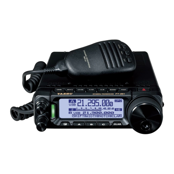
Yaesu FT-891 Operating Manual
Hf/50mhz transceiver
Hide thumbs
Also See for FT-891:
- Advance manual (114 pages) ,
- Technical supplement (99 pages) ,
- Operating manual (36 pages)
Table of Contents
Advertisement
Quick Links
Advertisement
Table of Contents

Related Manuals for Yaesu FT-891


Summary of Contents for Yaesu FT-891
- Page 1 FT-891 Operating Manual HF/50MHz TRANSCEIVER...
-
Page 2: Table Of Contents
Contents Introduction ............ 1 Operating Instructions 1 ......32 Safety Precautions ........2 DIAL knob Lock ........... 32 NB ( Noise Blanker ) Accessories & Options ......... 5 ( SSB/CW/RTTY/DATA/AM Modes ) ... 32 Supplied Accessories ........5 Operating Instructions 2 ......33 Optional Accessories ........ -
Page 3: Introduction
Computer Interface capability We urge you to read this manual and also the Advance Manual ( available for download on the Yaesu website ) in its entirety, to gain a full understanding of the amazing capability of the exciting new FT-891 Transceiver. -
Page 4: Safety Precautions
Do not transmit in crowded places in con- medical treatment immediately. sideration of people who are fitted with medical devices such as heart pacemak- ers. Electromagnetic waves from the device may affect the medical device, resulting in acci- dents caused by malfunctions. FT-891 Operating Manual... - Page 5 This may result in fire, electric shock and of the DC power equipment connected to the equipment failure. product out of the AC socket. Never touch the antenna as well. This may result in fire, electric shock and equipment failure due to thunder. FT-891 Operating Manual...
- Page 6 ( inverters etc. ) This may result in injury, electric shock and fitted in the car. equipment failure. FT-891 Operating Manual...
-
Page 7: Accessories & Options
Remote Control Keypad YSK-891 Separation Kit MMB-82 Mobile Mounting Bracket SCU-17 USB Interface Unit CT-58 VL-1000 Linear Amplifier Connection Cable CT-39A Packet Interface Cable AC Power Supply ( 25 A ) ( USA and Asian market only ) FP-1030A FT-891 Operating Manual... -
Page 8: Installing The Radio
Construct the antenna and coaxial cable, or use a suitable antenna tuner, to maintain the impedance presented to the FT-891 antenna connector for an SWR of 1.5 or less. Careful preparation of the antenna and/or tuner will permit maximum performance and protect the transceiver from damage. -
Page 9: Precautions During Installation
Ensure that the antenna base is securely grounded to the car body. r Avoid routing the co-axial cable enclosed with a commercial car antenna cable. r Do not place the co-axial cable or connectors inside the car where rain water or moisture may penetrate them. FT-891 Operating Manual... -
Page 10: Install The Main Body
Install the main body Install the main body using the provided MMB-82 bracket. r Do not install the FT-891 in a place with intense vibration. r Attach the bracket firmly with the supplied screws, so it will not become loose. -
Page 11: Connection Of Antenna And Power Cables
Permanent damage can result when improper supply voltage, or reverse polarity voltage, is applied to the FT-891. The Limited Warranty on this transceiver does not cover damage caused by application of AC voltage, reverse polarity DC, or DC voltage outside the specified range of 13.8 V ±15 %. -
Page 12: Before You Begin
4. Install the Front Panel by sliding it into the position shown; you will hear a “click” when the panel locks into place. MODE FT-891 HF/50MHz TRANSCEIVER Slide the Front Panel FT-891 Operating Manual... -
Page 13: Mh-31A8J Microphone Key Buttons
Speak into the microphone in a normal tone of voice with the microphone 5 cm away from your mouth. TONE Switch Alters transmit sound quality. Slide the switch to the “1” position for a “flat transmit audio response, Slide the switch to the “2” position to emphasize transmit audio. FT-891 Operating Manual... -
Page 14: Control Panel Switch & Connectors
Adjusting the Main tuning DIAL torque The torque ( drag ) of the Main Tuning DIAL knob may be adjusted for your operating preferences. Slide the lever clockwise to reduce the drag, or counter-clockwise to increase the drag. Increase Reduce FT-891 Operating Manual... -
Page 15: Base Station Tilt Stand
The sturdy stand on the bottom of the transceiver allows the transceiver to be tilted upward for better viewing. Simply fold the stand forward to raise the front of the transceiver, and fold it back against the bottom case to lower the front of the FT-891. FT-891 Operating Manual... -
Page 16: Resetting The Microprocessor
Use this procedure to reset ( clear ) the previously stored Memory channels, without affecting any configuration changes you may have made to the Menu settings. NOTE: The FT-891 cannot erase the memory channels “01” ( and “501” through “510”: U.S. version ) . -
Page 17: Function Resetting
Menu Mode “17-01 [ RESET ] ”. 3. Press the MULTI function knob, and then rotate the MULTI function knob to select “FUNC”. 4. Press and hold the MULTI function knob to reset and automatically restart the trans- ceiver. FT-891 Operating Manual... -
Page 18: Adjusting The Display Settings
4. When the adjustment is completed, press the MULTI function knob. [ F ] key to save the new setting and exit the Menu mode to normal oper- 5. Press the ation. FT-891 Operating Manual... -
Page 19: Front Panel Controls & Switches
The tuning steps for the for one step and 20 kHz for each dial rotation, in the SSB/AM/CW/RTTY/DATA Mode ( One kHz for each step and 200 kHz for each dial rotation in the FM Mode ) . FT-891 Operating Manual... - Page 20 V ] key This key will copy the saved data from a written memory channel to VFO-A. Press this key to display the “MEMORY CHANNEL” list screen. Rotate the MULTI function knob to select the desired previously written memory FT-891 Operating Manual...
- Page 21 1. Press this key to display the IF SHIFT screen. 2. Rotate the MULTI function knob to the left or right to reduce interfering sig- nals. MULTI function knob to restore the IF SHIFT setting to the 3. Press and hold the factory default. FT-891 Operating Manual...
-
Page 22: Main Dial
The SWP icon blinking on the LCD is confirmation that the “Contin- uous Sweeping mode” is running. ● Since the FT-891 has only one receiver the audio will be muted while the spectrum scope is scanning. To stop scanning and turn the receiver on, set the desired frequency and press the [ B ]( SWP ) key again. - Page 23 MULTI function knob This knob incorporates multiple tasks and makes it very convenient to operate the various functions of the FT-891: 1 Adjusts the operating frequency of VFO-A in 500 kHz Steps ( except the for AM and FM modes ) By pressing the MULTI function Knob momentarily until the “...
- Page 24 ● Reset the setting values to the factory default value ( Rotate the MULTI function Knob to select the function, and then press and hold the MULTI function Knob ) 6 Changes the Menu Mode setting values Refer to the “Menu Mode” on page 51. FT-891 Operating Manual...
-
Page 25: About The Display
The VOX function is in use The Narrow IF DSP filter is in use The Speech Processor function is The noise blanker is in use in use MAIN DIAL at a higher step rate. The Monitor function is in use FT-891 Operating Manual... -
Page 26: About The Rear Panel
Connection Cable. Connect an External Automatic Antenna Tuner FC-40,FC-50 with the control cable supplied with the tuner. NOTE: For details, refer to the Advanced Manual ( download from the Yaesu website ) . ① TX INH ② ② RESET (BAND D) ①... - Page 27 Keyup is 5 volts, and key down current is 1 mA. Use only the 3.5 mm 3 contact type plug. An incorrect size plug may damage the jack. If the Keyer plug is inserted into and removed from the jack while the FT-891 is in operation, the FT-891 may be switched to the transmit mode.
- Page 28 DC IN Jack This is the DC power supply connection for the transceiver. Use the supplied DC cable to connect directly to a DC power supply, which must be capable of supplying at least 23 A @13.8 VDC. FT-891 Operating Manual...
-
Page 29: Begin Using Your New Transceiver
ó 18 MHz ó 21 MHz ó 24 MHz ó ó 28 MHz ó 50 MHz ó... NOTE: When the desired operating Band is selected, the display will automati- cally return to normal operation after 0.5 second. FT-891 Operating Manual... -
Page 30: Setting The Operating Frequency
Operating Mode Frequency Step 50, 100, 500 ( kHz ) SSB, CW, RTTY, DATA 2.5, 5, 9, 10, 12.5, 25 ( kHz ) 5, 6.25, 10, 12.5, 15, 20, 25 ( kHz ) ( Default: Bold Italic ) FT-891 Operating Manual... -
Page 31: Using The Up/Dwn Keys Of The Supplied Mh-31A8J Hand Microphone
0.5 second. r After changing the selected operating mode on an amateur band, that same mode will automatically be selected when returning to that band. FT-891 Operating Manual... -
Page 32: Transmission ( Ssb/Am/Fm Mode )
When transmitting in the AM mode, set a maximum ( carrier ) power output of 40 Watts via Menu mode “16-02 [ HF AM PWR ] ” or “16-05 [ 50M AM PWR ] ”. 2. Release the PTT switch to return to receive mode. FT-891 Operating Manual... -
Page 33: Qmb ( Quick Memory Bank ) Channels
5. Press and hold the MULTI function knob, to erase the contents of the selected QMB channel. [ A ]( BCK ) key. 6. To exit from QMB mode and return to the VFO mode, press the FT-891 Operating Manual... -
Page 34: Operating Instructions 1
[ PWR/LOCK ] key again. tuning, press the NB ( Noise Blanker ) ( SSB/CW/RTTY/DATA/AM Modes ) The FT-891 includes an effective IF Noise Blanker, which can significantly reduce noise caused by automotive ignition systems. [ C ]( NB ) key to turn 1. -
Page 35: Operating Instructions 2
VFO-A frequency setting. A small four digit indication on the display will show the current Clarifier offset. The Clarifier functions on the FT-891 allow offsetting the receive and transmit frequencies ( up to ±9.998 kHz ) , without [ CLAR ] key. This feature... -
Page 36: Operating Instructions 3
( C ) , you can see the effect of rotating MULTI MULTI MULTI MULTI function knob. The inter- ference level is reduced by moving the filter passband so that the interference is outside of the passband. FT-891 Operating Manual... -
Page 37: Operating Instructions 4
[ F ] key repeatedly to find the “FUNCTION-2” ranges in the voice waveform. Press the list screen. à Rotate the MULTI function knob to select “MEQ”. à Press the MULTI function knob to switch the microphone equalizer ON or OFF. FT-891 Operating Manual... -
Page 38: Scope
Sweeping mode”, the scope spectrum is repeatedly swept and displayed. The scope sweep and span may be optimized according to your preferences and purposes. NOTE: Since the FT-891 has only one receiver the audio will be muted during the Continuous sweeping mode. -
Page 39: Operation On 60-Meter ( 5 Mhz ) Band ( U.s. And U.k. Version Only )
Operation on 60-Meter ( 5 MHz ) Band ( U.S. and U.K. Version Only ) The recently authorized 60-meter band is covered, in the FT-891, by fixed memory channels. These channels are set to USB or CW, and they appear between the “last”... -
Page 40: Memory Operation
For details about operation of the following functions, refer to the Advanced Manual ( download from the Yaesu website ) . Naming a Memory Channel You may also append an alphanumeric “Tag” ( label ) to each memory, to aid in recollection of the channel’s use ( such as club name, etc. -
Page 41: Memory Channel Recall
1. Press the 2. Rotate the MULTI function knob to select the desired memory channel. V ] key, copies the data from the selected memory to VFO-A. Pre- 3. Pressing the vious data in VFO-A will be overwritten. FT-891 Operating Manual... -
Page 42: Erasing Memory Channel Data
2. Rotate the MULTI function knob to select the memory channel that is to be erased. NOTE: The FT-891 cannot erase memory channel “01” ( and channels “501” through “510”: U.S. version ) . [ C ]( ERS ) key to erase the con- 3. -
Page 43: Scanning Operation
Scanning Operation You may scan either the VFO or the memories of the FT-891, and the radio will halt scanning on any frequency with a signal strong enough to open the receiver squelch. VFO Scanning 1. Set VFO-A to the frequency on which you would like to begin scanning. -
Page 44: Memory Scanning
Programmable Memory Scan ( PMS ) When scanning the dedicated PMS memory channels, only the frequencies within the specified frequency range will be scanned. NOTE: For additional details, refer to the Advanced Manual which may be downloaded from the Yaesu website. FT-891 Operating Manual... -
Page 45: Cw Mode Operation
The CW sidetone volume level can be adjusted via the “FUNCTION-1” list screen. NOTE: For additional details, refer to the Advanced Manual which may be downloaded from the Yaesu website. Adjusting the Keyer Speed The keyer speed can be adjusted via the “CW SETTING” list screen. -
Page 46: Setting Modes
MULTI function knob to press the close the pop-up screen. [ F ] key for one second, or rotate the DIAL knob to exit the “Set- 4. Press and hold the ting Modes” screen and resume normal operation. FT-891 Operating Manual... -
Page 47: Changing The Function Assigned To The [ A ] / [ B ] / [ C ] Keys
[ A ] / [ B ] / [ C ] key display as shown in the case of the NOTE: Examples of the Function Noise Blanker : Function “OFF”. : Function “ON”. : Function “ON” and then turn the MULTI function knob to change the assigned feature setting. FT-891 Operating Manual... -
Page 48: Function-1
Notch filter, then press the MULTI function knob to close the pop-up screen. • Press the MULTI function knob to turn the IF NOTCH filter feature OFF. NOTE: For details, refer to the Advanced Manual ( download from the Yaesu website ) . FT-891 Operating Manual... -
Page 49: Function-2
During a split operation, to listen on the transmit frequency. Press and hold Press Enable/Disable the Parametric Microphone Equalizer. Press To display the “QMB CHANNEL” list screen. NOTE: For details, refer to the Advanced Manual ( download from the Yaesu website ) . FT-891 Operating Manual... -
Page 50: Cw Setting
Rotate the MULTI function knob to adjust the PITCH ( 300 - 1050 Hz ) . PITCH Press KEYER Press Enable/Disable the built-in Electronic Keyer. BK-IN Press Enable/Disable the CW “Semi break-in” operation. NOTE: For details, refer to the Advanced Manual ( download from the Yaesu website ) . FT-891 Operating Manual... -
Page 51: Fm Setting
MULTI function knob to close the pop-up screen. Reverse the transmit and receive frequencies while working through a re- Press peater. NOTE: For details, refer to the Advanced Manual ( download from the Yaesu website ) . CTCSS TONE FREQUENCY ( Hz ) 67.0 69.3 71.9... -
Page 52: Rec Setting
Press Send the CW message which is prerecorded in CW MEMORY 5. NOTE: For details, refer to the Advanced Manual ( download from the Yaesu website ) . ATAS SETTING This setting mode is used when connecting the Active Tuning Antenna “ATAS-120A”. -
Page 53: Menu Mode
Menu Mode The FT-891 Menu mode, already described in parts of many previous chapters, is easy to activate and setup. The Menus may be used to configure many of transceiver parameters, some of which have not been detailed previously. Use the following procedure to activate... - Page 54 07-09 CW BK-IN DELAY 200msec 2/4 ( msec ) 07-10 CW WAVE SHAPE 4msec 07-11 CW FREQ DISPLAY FREQ/PITCH PITCH 07-12 PC KEYING OFF/DAKY/RTS/DTR 15/20/25/30 ( msec ) 07-13 QSK DELAY TIME 15msec : European Version. ø FT-891 Operating Manual...
- Page 55 SSB PTT SELECT DAKY/RTS/DTR DAKY 100-3000/100-2900/200-2800/300- 300-2700 11-09 SSB TX BPF 2700/400-2600 RX DSP 12-01 APF WIDTH NARROW/MEDIUM/WIDE MEDIUM 12-02 CONTOUR LEVEL -40 - 0 - 20 12-03 CONTOUR WIDTH 1 - 11 12-04 IF NOTCH WIDTH NARROW/WIDE WIDE FT-891 Operating Manual...
- Page 56 0 - 100 16-12 AM DATA GAIN 0 - 100 16-13 FM DATA GAIN 0 - 100 16-14 DATA DATA GAIN 0 - 100 16-15 TUNER SELECT OFF/EXTERNAL/ATAS/LAMP 16-16 VOX SELECT MIC/DATA 16-17 VOX GAIN 0 - 100 FT-891 Operating Manual...
- Page 57 30 - 3000 ( msec ) 16-21 DATA VOX DELAY 100msec 16-22 ANTI DVOX GAIN 0 - 100 16-23 EMERGENCY FREQ ENABLE/DISABLE DISABLE RESET 17-01 RESET ALL/DATA/FUNC VERSION 18-01 MAIN VERSION 18-02 DSP VERSION 18-03 LCD VERSION FT-891 Operating Manual...
-
Page 58: Specifications
Better than -50 dB ( 1.8 MHz - 30 MHz Amateur bands ) Spurious Radiation: Better than -63 dB ( 50 MHz Amateur bands ) 600 Ohms ( 200 Ohms to 10 k Ohms ) Microphone Impedance: FT-891 Operating Manual... - Page 59 Audio Output Impedance: Conducted Radiation: Less than 4 nW Specifications are subject to change, in the interest of technical improvement, without notice or obligation, and are guaranteed only within the amateur bands. Symbol placed on the equipment Direct current FT-891 Operating Manual...
- Page 60 Consult the dealer or an experienced radio/TV technician for help. 1. Changes or modifications to this device that are not expressly approved by YAESU MUSEN could void the user’s authorization to operate this device. 2. This device complies with part 15 of the FCC Rules. Operation is subject to the following two conditions: ( 1 ) This device may not cause harmful interference, and ( 2 ) this device must accept any interference including received, interference that may cause undesired operation.
-
Page 61: Declaration Of Conformity
Fax: +44 (0)1962 856801 Email: sales@yaesu.co.uk Declaration of Conformity Nr. YUK-DOC-0601-16 We, Yaesu UK Ltd. certify and declare under our sole responsibility that the following equipment complies with the essential requirements of the Directive 1999/5/EC and 2011/65/EU. Type of Equipment HF/50MHz Transceiver... - Page 62 Copyright 2016 YAESU MUSEN CO., LTD. All rights reserved. No portion of this manual may be reproduced without the permission of YAESU MUSEN CO., LTD. YAESU MUSEN CO., LTD. Tennozu Parkside Building 2-5-8 Higashi-Shinagawa, Shinagawa-ku, Tokyo 140-0002 Japan 1609C-AO-1 YAESU USA Printed in Japan 6125 Phyllis Drive, Cypress, CA 90630, U.S.A.