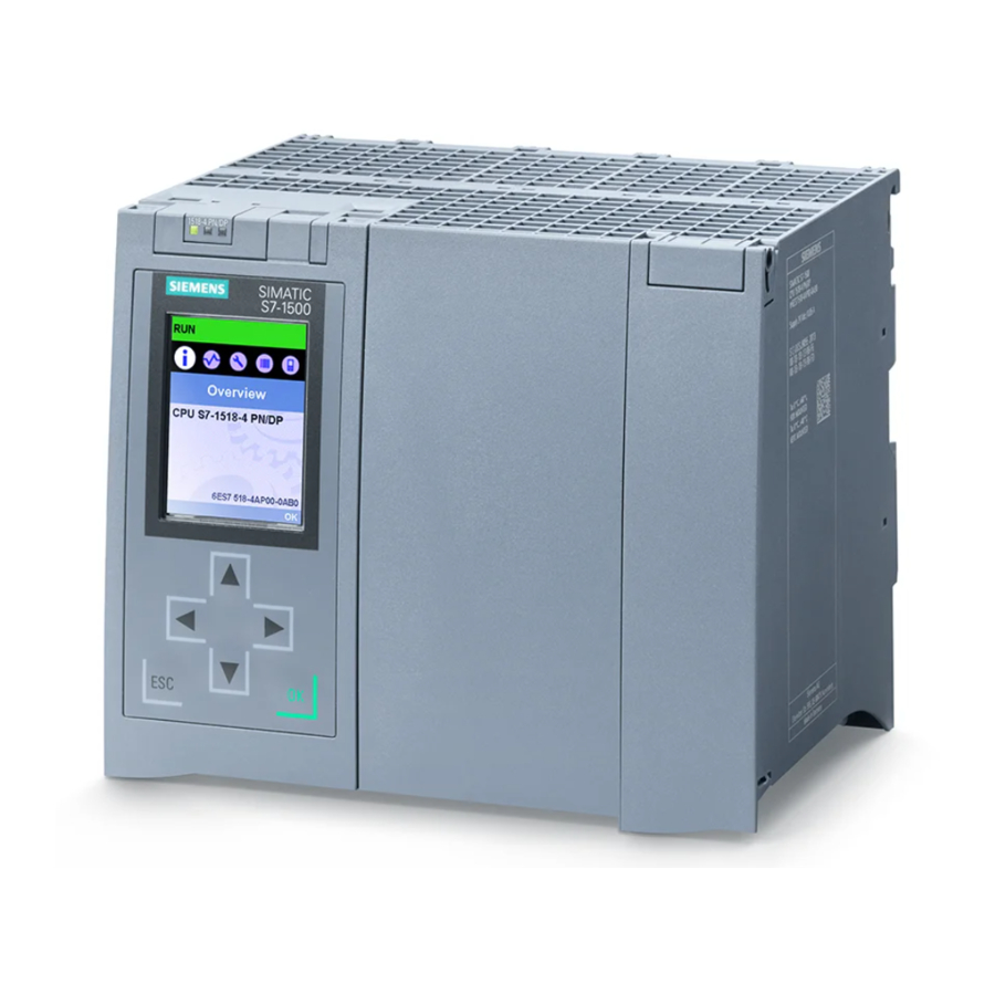
Siemens Simatic S7-1500 Manual
Simatic s7-1500/et 200mp
digital input module f-di
16x24vdc
Hide thumbs
Also See for Simatic S7-1500:
- System manual (523 pages) ,
- Function manual (402 pages) ,
- Manual (188 pages)
Table of Contents
Advertisement
Advertisement
Table of Contents

Related Manuals for Siemens Simatic S7-1500


Summary of Contents for Siemens Simatic S7-1500
- Page 1 Translation of original operating instructions...
- Page 2 ___________________ Digital input module Preface F-DI 16x24VDC ___________________ Documentation guide (6ES7526-1BH00-0AB0) ___________________ SIMATIC Product overview ___________________ Connecting ET 200MP Digital input module ___________________ F-DI 16x24VDC Parameters/address space (6ES7526-1BH00-0AB0) ___________________ Applications of the F-I/O module Manual ___________________ Interrupts/diagnostic messages ___________________ Technical specifications ___________________ Response times ___________________...
- Page 3 Note the following: WARNING Siemens products may only be used for the applications described in the catalog and in the relevant technical documentation. If products and components from other manufacturers are used, these must be recommended or approved by Siemens. Proper transport, storage, installation, assembly, commissioning, operation and maintenance are required to ensure that the products operate safely and without any problems.
-
Page 4: Preface
S7-1500 automation system and the ET 200MP distributed I/O system in the system manual S7-1500 Automation System (http://support.automation.siemens.com/WW/view/en/59191792). The information provided in this manual and the system manual enables you to commission the S7-1500 automation system and ET 200MP distributed I/O system. - Page 5 Siemens recommends strongly that you regularly check for product updates. For the secure operation of Siemens products and solutions, it is necessary to take suitable preventive action (e.g. cell protection concept) and integrate each component into a holistic, state-of-the-art industrial security concept.
- Page 6 Siemens accepts no liability for the use of the open source software over and above the intended program sequence, or for any faults caused by modifications to the software.
-
Page 7: Table Of Contents
Table of contents Preface ..............................4 Documentation guide ..........................9 Guide to documentation S7-1500 / ET 200MP ................. 9 Product overview ..........................12 Properties ..........................12 Connecting ............................15 Block diagram ......................... 15 Parameters/address space ........................17 Parameters ..........................17 Explanation of parameters ...................... - Page 8 Table of contents Interrupts/diagnostic messages ......................47 Status and error displays ....................... 47 Interrupts ..........................50 Diagnostic alarms........................51 Technical specifications ........................57 Response times ............................ 60 Open Source Software .......................... 62 Digital input module F-DI 16x24VDC (6ES7526-1BH00-0AB0) Manual, 01/2016, A5E03858068-AA...
-
Page 9: Documentation Guide
This arrangement enables you to access the specific content you require. Basic information The System Manual and Getting Started describe in detail the configuration, installation, wiring and commissioning of the SIMATIC S7-1500 and ET 200MP systems. The STEP 7 online help supports you in the configuration and programming. Device information Product manuals contain a compact description of the module-specific information, such as properties, wiring diagrams, characteristics and technical specifications. - Page 10 1.1 Guide to documentation S7-1500 / ET 200MP Manual Collection S7-1500/ET 200MP The Manual Collection contains the complete documentation on the SIMATIC S7-1500 automation system and the ET 200MP distributed I/O system gathered together in one file. You can find the Manual Collection on the Internet (http://support.automation.siemens.com/WW/view/en/86140384).
- Page 11 With the TIA Selection Tool, you can generate a complete order list from your product selection or product configuration. You can find the TIA Selection Tool on the Internet (http://w3.siemens.com/mcms/topics/en/simatic/tia-selection-tool). Digital input module F-DI 16x24VDC (6ES7526-1BH00-0AB0) Manual, 01/2016, A5E03858068-AA...
-
Page 12: Product Overview
Product overview Properties Order number 6ES7526-1BH00-0AB0 View of the module Image 2-1 View of the F-DI 16x24VDC module Digital input module F-DI 16x24VDC (6ES7526-1BH00-0AB0) Manual, 01/2016, A5E03858068-AA... - Page 13 Product overview 2.1 Properties Properties ● Technical properties – Fail-safe digital module for use in the S7-1500 automation system and in the ET 200MP distributed I/O system. – PROFIsafe – PROFIsafe address type 2 – Supports the RIOforFA-Safety profile (on S7-1500 F-CPUs) –...
- Page 14 The following component is to be ordered separately: ● Front connector incl. potential bridges and cable ties You can find additional information on accessories in the S7-1500/ET 200MP (http://support.automation.siemens.com/WW/view/en/59191792) system manual. Digital input module F-DI 16x24VDC (6ES7526-1BH00-0AB0) Manual, 01/2016, A5E03858068-AA...
-
Page 15: Connecting
F-I/O module (Page 32). You can find information on wiring the front connectors and creating the cable shielding, etc., in the Wiring section of the system manual Automation System S7-1500 (http://support.automation.siemens.com/WW/view/en/59191792). Digital input module F-DI 16x24VDC (6ES7526-1BH00-0AB0) Manual, 01/2016, A5E03858068-AA... - Page 16 Connecting 3.1 Block diagram Block diagram The following figure shows the assignment of channels to addresses (input byte a and input byte b). ① Backplane bus interface Supply voltage 24 V DC ② Microcontroller 1 Chassis ground ③ Microcontroller 2 Channel or LED channel status, channel diag- nostics (green, red) ④...
-
Page 17: Parameters/Address Space
Parameters/address space Parameters Parameters WARNING Diagnostic functions must be activated or deactivated in accordance with the application, see section Applications of the F-I/O module (Page 32). Table 4- 1 Parameters for F-DI 16x24VDC Parameter Value range Parameter reas- Scope signment in RUN F-parameters: Manual assignment of F-monitoring time Module... - Page 18 Parameters/address space 4.1 Parameters Parameter Value range Parameter reas- Scope signment in RUN Supplied channels Sensor supply 0: Channel group No channels • Channels [0..3] • Channels [0..7] • Channels [0..15] • Sensor supply 1: No channels • Channels [4..7] •...
- Page 19 Parameters/address space 4.2 Explanation of parameters Parameter Value range Parameter reas- Scope signment in RUN Input delay Channel 0.4 ms • 0.8 ms • 1.6 ms • 3.2 ms • 6.4 ms • 10.0 ms • 12.8 ms • 20.0 ms •...
-
Page 20: Explanation Of Parameters
You can find information on F-parameters for the F-monitoring time, the PROFIsafe address assignment (F-source address, F-destination address) and the F I/O DB in the manual SIMATIC Safety - Configuring and Programming (http://support.automation.siemens.com/WW/view/en/54110126). 4.2.1.1 Behavior after channel fault This parameter is used to specify whether the entire F-module is passivated or just the faulty channel(s) in the event of channel faults: ●... -
Page 21: Parameters Of The Sensor Supply
Parameters/address space 4.2 Explanation of parameters 4.2.2 Parameters of the sensor supply 4.2.2.1 Supplied channels With this parameter, you specify whether and which internal sensor supply supplies which channel groups. The choice taken applies to the entire channel group (CH0-3, 4-7, 8-11, 12-15). -
Page 22: Time For Short-Circuit Test
Parameters/address space 4.2 Explanation of parameters The short-circuit detection switches off the internal sensor supply briefly. The length of the deactivation period is equivalent to the configured "Time for sensor test". If a short-circuit is detected, the F-module triggers a diagnostic interrupt and the input is passivated. -
Page 23: Startup Time Of Sensors After Short-Circuit Test
Parameters/address space 4.2 Explanation of parameters 4.2.2.4 Startup time of sensors after short-circuit test Function In addition to the switch-off time ("Time for short-circuit test"), a startup time must be specified for performing the short-circuit test. You use this parameter to notify the module how long the utilized sensor needs to start up after turning on the internal sensor supply. -
Page 24: Discrepancy Behavior
Parameters/address space 4.2 Explanation of parameters 1oo2 evaluation, equivalent/non-equivalent With a 1oo2 evaluation equivalent/non-equivalent, two input channels are occupied by: ● a two-channel equivalent/non-equivalent sensor ● Two single-channel sensors The input signals are compared internally for equivalence or non equivalence. Note that in 1oo2 evaluation, two channels are combined into a channel pair. -
Page 25: Discrepancy Time
Parameters/address space 4.2 Explanation of parameters Supply last valid value" The most recent valid value (old value) before the discrepancy occurred is made available to the safety program in the F-CPU as soon as a discrepancy is detected between the signals of the two affected input channels. -
Page 26: Reintegration After Discrepancy Error
Parameters/address space 4.2 Explanation of parameters Behavior after expiration of the discrepancy time If no agreement (when checking for non equivalence: inequality) of the input signals exists once the assigned discrepancy time expires, for example, due to a break in a sensor wire, a discrepancy error is detected and the "Discrepancy error"... -
Page 27: Input Delay
(see section "Electromagnetic compatibility" in the system manual S7-1500 Automation System (http://support.automation.siemens.com/WW/view/en/59191792)). If the interference pulses occur with a short-circuit test, the fail-safe digital inputs are passivated. Increase the input delay or use shielded signal lines in order to prevent possible passivation of the fail-safe digital inputs and switch-off of the internal sensor supply. -
Page 28: Channel Failure Acknowledge
The value of this parameter is not relevant in the case of operation on S7-300/400 F-CPUs. There you set the corresponding property at the F-I/O DB by means of the ACK_NEC tag. For detailed information about the F-I/O DB, refer to the SIMATIC Safety – Configuring and Programming (http://support.automation.siemens.com/WW/view/en/54110126) manual. 4.2.4.4 Pulse extension Function Pulse extension is a function to extend a digital input signal. -
Page 29: Number Of Signal Changes
Parameters/address space 4.2 Explanation of parameters Recognizing unusual signal patterns An assigned monitoring window is available for each input channel. The monitoring window starts with the first signal change of the input signal. If the input signal changes within the monitoring window at least as often as the assigned "Number of signal changes", a chatter error is detected. -
Page 30: Address Space
Parameters/address space 4.3 Address space Address space Address assignment of the digital input module F-DI 16x24VDC The digital input module F-DI 16x24VDC occupies the following address areas in the F-CPU: Table 4- 2 Address assignment in the F-CPU Occupied bytes in the F-CPU: F-CPU In input range In output range... - Page 31 CH0. Additional information For detailed information about F-I/O access and for evaluation and processing of the value status, refer to the SIMATIC Safety – Configuring and Programming (http://support.automation.siemens.com/WW/view/en/54110126) manual. Digital input module F-DI 16x24VDC (6ES7526-1BH00-0AB0) Manual, 01/2016, A5E03858068-AA...
-
Page 32: Applications Of The F-I/O Module
Applications of the F-I/O module Applications of the F-DI 16x24VDC Selecting the application The diagram below supports you in selecting the application that suits your fail-safe requirements. In the following sections, you will learn how to wire the F-module, the specific parameters you must assign in STEP 7 Safety and the errors that are detected. - Page 33 Sensor requirements Information on the safety-related use of sensors is available in the section Requirements for sensors and actuators for fail-safe modules of the system manual S7-1500 Automation System (http://support.automation.siemens.com/WW/view/en/59191792). Digital input module F-DI 16x24VDC (6ES7526-1BH00-0AB0) Manual, 01/2016, A5E03858068-AA...
-
Page 34: Application 1: Safety Mode Sil3/Cat.3/Pld
Wiring The wiring is carried out on the front connector of the module. Refer to the "Wiring" section in the S7-1500 Automation System (http://support.automation.siemens.com/WW/view/en/59191792) system manual. Sensor supply The sensor supply can be powered internally or externally. Wiring diagram – connecting one sensor via one channel One sensor is connected via one channel (1oo1 evaluation) for each process signal. - Page 35 Applications of the F-I/O module 5.2 Application 1: Safety mode SIL3/Cat.3/PLd The figure below shows an example of the pin assignment of the fail-safe digital input module F-DI 16x24VDC with one-channel connection of a sensor. ① ③ Backplane bus interface Microcontroller 2 ②...
- Page 36 Applications of the F-I/O module 5.2 Application 1: Safety mode SIL3/Cat.3/PLd Parameter assignment Assign the following parameters for the corresponding channel: Table 5- 2 Parameter assignment Parameter Channel with internal sensor sup- Channel with external sensor supply Sensor evaluation 1oo1 evaluation Supplied channels Channels [x...y] None...
-
Page 37: Application 2: Safety Mode Sil3/Cat.3/Ple
Wiring The wiring is carried out on the front connector of the module. Refer to the "Wiring" section in the S7-1500 Automation System (http://support.automation.siemens.com/WW/view/en/59191792) system manual. Sensor supply The sensor supply can be powered internally or externally. Digital input module F-DI 16x24VDC (6ES7526-1BH00-0AB0) - Page 38 Applications of the F-I/O module 5.3 Application 2: Safety mode SIL3/Cat.3/PLe Wiring diagram – connecting a two-channel sensor equivalent A two-channel sensor is connected equivalent to two inputs of the F-module for each process signal (1oo2 evaluation). You can also supply one or both sensor switches by means of an external sensor supply. The figure below shows an example of the pin assignment of the fail-safe digital input module F-DI 16x24VDC with equivalent connection of a two-channel sensor.
- Page 39 Applications of the F-I/O module 5.3 Application 2: Safety mode SIL3/Cat.3/PLe Wiring diagram – connecting two single-channel sensors via two channels Two single-channel sensors that capture the same process value are connected to two inputs of the F-module for each process signal (1oo2 evaluation). You can also supply the sensors by means of an external sensor supply.
- Page 40 Applications of the F-I/O module 5.4 Application 3: Safety mode SIL3/Cat.4/PLe Parameter assignment Assign the following parameters for the corresponding channel: Table 5- 4 Parameter assignment Parameter Channel with internal sensor supply Channel with external sensor supply Sensor evaluation 1oo2 evaluation, equivalent Supplied channels Channels [x...y] None...
-
Page 41: Application 3: Safety Mode Sil3/Cat.4/Ple
The wiring is carried out on the front connector of the module. Refer to the "Wiring" section in the S7-1500 Automation System (http://support.automation.siemens.com/WW/view/en/59191792) system manual. Sensor supply The sensor must be supplied internally by at least one channel group for application 3.1. -
Page 42: Application 3.1 (Sil3/Cat.4/Ple)
Applications of the F-I/O module 5.4 Application 3: Safety mode SIL3/Cat.4/PLe 5.4.1 Application 3.1 (SIL3/Cat.4/PLe) Wiring diagram – connecting a two-channel sensor via two channels A two-channel sensor is connected to two inputs of the F-module for each process signal (1oo2 evaluation). - Page 43 Applications of the F-I/O module 5.4 Application 3: Safety mode SIL3/Cat.4/PLe Parameter assignment Assign the following parameters for the corresponding channel: Table 5- 6 Parameter assignment Parameter Channel with internal sensor supply Sensor evaluation 1oo2 evaluation, equivalent Supplied channels Channels [x...y] Short-circuit test activated Enable Fault detection...
-
Page 44: Use Case 3.2 (Sil3/Cat.4/Ple)
Applications of the F-I/O module 5.4 Application 3: Safety mode SIL3/Cat.4/PLe 5.4.2 Use case 3.2 (SIL3/Cat.4/PLe) Wiring diagram – connecting a non-equivalent sensor A non-equivalent sensor is connected to two inputs of the F-module for each process signal (1oo2 evaluation, non-equivalent). You can also supply the sensor by means of an external sensor supply. - Page 45 Applications of the F-I/O module 5.4 Application 3: Safety mode SIL3/Cat.4/PLe Wiring diagram – connecting two single-channel sensors non-equivalent Two single-channel sensors are connected non-equivalent to two inputs of the F-module for each process signal (1oo2 evaluation). You can also supply one or both sensors by means of an external sensor supply. The figure below shows an example of the pin assignment of the fail-safe digital input module F-DI 16x24VDC with non-equivalent connection of two single-channel sensors.
- Page 46 Applications of the F-I/O module 5.4 Application 3: Safety mode SIL3/Cat.4/PLe Parameter assignment Assign the following parameters for the corresponding channel: Table 5- 8 Parameter assignment Parameter Channel with internal sensor supply Channel with external sensor supply Sensor evaluation 1oo2 evaluation, non-equivalent Supplied channels Channels [x...y] None...
-
Page 47: Interrupts/Diagnostic Messages
Interrupts/diagnostic messages Status and error displays LED displays Image 6-1 LED displays of the F-DI 16x24VDC module Meaning of the LED displays The following tables explain the meaning of the status and error displays. Remedies for diagnostic alarms can be found in section Diagnostic alarms (Page 51). WARNING The RUN, ERROR LEDs and channel status/channel diagnostics LEDs of the inputs are not designed as safety-related LEDs and therefore may not be evaluated for safety-related... - Page 48 Acknowledge the error (see manual SIMATIC Operation in S7-1500 F-CPUs: The F- • Safety - Configuring and Programming Alternately flashing module expects user acknowledgment after (http://support.automation.siemens.com/WW/vi a module error. ew/en/54110126)). Operation in S7-300/400 F-CPUs: At least • one channel is waiting for user acknowl- edgment.
- Page 49 Interrupts/diagnostic messages 6.1 Status and error displays CHx LED Table 6- 3 Display channel status/channel diagnostics Status CHx Diagnostics Meaning Process signal = 0 and no channel diagnostics* Process signal = 1 and no channel diagnostics Process signal = 0 and channel diagnostics Channel waiting for user acknowledgment Alternately flashing * Operation in S7-300/400 F-CPUs only: If necessary, wait for user acknowledgment, if an additional...
-
Page 50: Interrupts
Interrupts/diagnostic messages 6.2 Interrupts Interrupts Introduction The F-DI 16x24VDC fail-safe digital input module supports diagnostic interrupts. Diagnostic interrupt The F-module generates a diagnostic interrupt for each diagnostic alarm described in section Diagnostic alarms (Page 51). The table below provides an overview of the diagnostic interrupts of the F-module . The diagnostic interrupts are assigned either to one channel or the entire F-module. -
Page 51: Diagnostic Alarms
Once the fault is eliminated, the F-module must be reintegrated in the safety program. For additional information on passivation and reintegration of F-I/O, refer to the SIMATIC Safety – Configuring and Programming (http://support.automation.siemens.com/WW/view/en/54110126) manual. Table 6- 7 Diagnostic alarms of the F-DI 16x24VDC... - Page 52 Interrupts/diagnostic messages 6.3 Diagnostic alarms Diagnostic alarm Fault Meaning Remedy code Supply voltage missing Missing or insufficient supply voltage L+ Check supply voltage L+ at the • front connector Check the front connector • Mismatch of safety destina- The firmware of the F-module has detected Check the parameter assignment •...
- Page 53 Interrupts/diagnostic messages 6.3 Diagnostic alarms Diagnostic alarm Fault Meaning Remedy code Module is defective Possible causes: Impermissibly high electromagnetic Eliminate the interference. The • • interference is present. module must then be pulled and plugged, or the power switched OFF and ON. The F-module has detected an internal If the F-module cannot be put •...
- Page 54 Interrupts/diagnostic messages 6.3 Diagnostic alarms Diagnostic alarm Fault Meaning Remedy code Input signal not recorded An error occurred during the plausibility Use shielded cables to reduce • unique check of the input signal between the pro- the EMC effects. cessors. Reduce the input frequency.
- Page 55 Interrupts/diagnostic messages 6.3 Diagnostic alarms Diagnostic alarm Fault Meaning Remedy code Sensor signal flutters Too many signal changes have occurred Check the "Monitoring window" • within the time configured with the "Monitor- parameter. ing window" parameter. Check the "Number of signal •...
- Page 56 Generally applicable information on diagnostics Information on diagnostics that pertains to all F-modules (for example, readout of diagnostics functions or passivation of channels) is available in the SIMATIC Safety – Configuring and Programming (http://support.automation.siemens.com/WW/view/en/54110126) manual. Digital input module F-DI 16x24VDC (6ES7526-1BH00-0AB0) Manual, 01/2016, A5E03858068-AA...
-
Page 57: Technical Specifications
Technical specifications Technical specifications of F-DI 16x24VDC 6ES7526-1BH00-0AB0 General information Product type designation F-DI 16x24VDC Firmware version FW update possible • Product function I&M data Yes; I&M0 to I&M3 Engineering with STEP 7 TIA Portal can be configured/integrated V13 SP1 with HSP0086 as of version Operating mode Supply voltage... - Page 58 Technical specifications 6ES7526-1BH00-0AB0 Digital inputs Number of inputs m/p-reading Yes; p-reading Input characteristic curve according to IEC 61131, Type 1 Input voltage Rated value (DC) 24 V For "0" signal -30 ... +5 V For "1" signal +15 ... +30 V Input current For "1"...
- Page 59 0 °C Vertical installation, max. 40 °C Dimensions Width 35 mm Height 147 mm Depth 129 mm Weights Weight, approx. 280 g Dimension drawing See system manual S7-1500 Automation System (http://support.automation.siemens.com/WW/view/en/59191792). Digital input module F-DI 16x24VDC (6ES7526-1BH00-0AB0) Manual, 01/2016, A5E03858068-AA...
-
Page 60: Response Times
Response times Introduction The next section shows the response times of the digital input module F-DI 16x24VDC. The response times of the digital input module F-DI 16x24VDC are included in the calculation of the F-system response time. Definition of cycle time for fail-safe digital inputs The cycle time indicates the time between the occurrence of an event and the transfer to the backplane bus. - Page 61 Response times Maximum response time to external short-circuits t <= max (120 ms, 2 * (n × cycle time) + sum [x=0...3](T1x + T2x)) + cycle time Time for the sensor test Startup time of sensors after the short-circuit test Number of sensor supplies with activated short-circuit test Sensor supply Maximum response time to discrepancy errors during 1oo2 evaluation...
-
Page 62: Open Source Software
Open Source Software Digital input module F-DI 16x24VDC (6ES7526-1BH00-0AB0) Manual, 01/2016, A5E03858068-AA... - Page 63 Open Source Software Digital input module F-DI 16x24VDC (6ES7526-1BH00-0AB0) Manual, 01/2016, A5E03858068-AA...
- Page 64 Open Source Software Digital input module F-DI 16x24VDC (6ES7526-1BH00-0AB0) Manual, 01/2016, A5E03858068-AA...
- Page 65 Open Source Software Digital input module F-DI 16x24VDC (6ES7526-1BH00-0AB0) Manual, 01/2016, A5E03858068-AA...
- Page 66 Open Source Software Digital input module F-DI 16x24VDC (6ES7526-1BH00-0AB0) Manual, 01/2016, A5E03858068-AA...
- Page 67 Open Source Software Digital input module F-DI 16x24VDC (6ES7526-1BH00-0AB0) Manual, 01/2016, A5E03858068-AA...
- Page 68 Open Source Software Digital input module F-DI 16x24VDC (6ES7526-1BH00-0AB0) Manual, 01/2016, A5E03858068-AA...
- Page 69 Open Source Software Digital input module F-DI 16x24VDC (6ES7526-1BH00-0AB0) Manual, 01/2016, A5E03858068-AA...
- Page 70 Open Source Software Digital input module F-DI 16x24VDC (6ES7526-1BH00-0AB0) Manual, 01/2016, A5E03858068-AA...
- Page 71 Open Source Software Digital input module F-DI 16x24VDC (6ES7526-1BH00-0AB0) Manual, 01/2016, A5E03858068-AA...