
Related Manuals for McIntosh C1100


Summary of Contents for McIntosh C1100
- Page 1 McIntosh Laboratory, Inc. 2 Chambers Street Binghamton, New York 13903-2699 Phone: 607-723-3512 www mcintoshlabs.com C1100 Controller and Tube Preamplifier Owner’s Manual...
-
Page 2: Safety Instructions
he lightning flash with arrowhead, within an equilateral triangle, The exclamation point within an equilateral triangle is intended to is intended to alert the user to the presence of uninsulated “dan- alert the user to the presence of important operating and mainte- gerous voltage”... -
Page 3: Table Of Contents
Thank You Customer Service Remote Control: Your decision to own this McIntosh C1100 Tube Pre- If it is determined that your McIntosh product is in HR085 Remote Control Push-buttons ...... 14 amplifier ranks you at the very top among discrimi- need of repair, you can return it to your Dealer. -
Page 4: General Information
9. Controller to Preamplifier Cable Part No. 171‑872 Note: The Power Control, Trigger, PASSTHRU and Data Connecting Cable is available from the McIntosh 3. The Main AC Power going to the C1100 and any is three foot, shielded 23 conductor, male-to-fe- Parts Department: other McIntosh Component(s) should not be applied male custom cable. -
Page 5: Introduction
Titanium Stainless Steel Finish. Source Selection, Volume/Balance Levels and Setup • Moving Coil and Moving Magnet Phono Inputs This will ensure the pristine beauty of the C1100 will Mode Selections. The display intensity is adjustable. The C1100T has two precision Phono Preamplifier be retained for many years to come. -
Page 6: C1100C Dimensions
C1100C Dimensions Dimensions The following dimensions can assist in determining the best location for your C1100C. There is additional information on the next page pertaining to installing the C1100C into cabinets. Front View of the C1100C " 44.5cm " 6" 13.7cm 15.2cm Side View of the C1100C... -
Page 7: C1100C Installation
C1100C Installation Installation " The C1100C can be placed upright on a table or 3/16 43.66cm shelf, standing on its four feet. It also can be custom installed in a piece of furniture or cabinet of your choice. The four feet may be removed from the bottom of the C1100C when it is custom installed as outlined Opening for Ventilation below. -
Page 8: C1100T Dimensions
C1100T Dimensions Dimensions The following dimensions can assist in determining the best location for your C1100T. There is additional information on the next page pertaining to installing the C1100T into cabinets. Front View of the C1100T " 44.5cm " 6" 13.7cm 15.2cm Side View of the C1100T... -
Page 9: C1100T Installation
C1100T Installation Installation " The C1100T can be placed upright on a table or 3/16 43.66cm shelf, standing on its four feet. It also can be custom installed in a piece of furniture or cabinet of your choice. The four feet may be removed from the bottom of the C1100T when it is custom installed as outlined Opening for Ventilation below. -
Page 10: C1100C And C1100T Rear Panel Connections
Rear Panel Connections The identification of Rear Panel Connections for the C1100C Controller and C1100T Tube Preamplifier is located on a separate folded sheet contained in the Owner’s Manual Packet. Refer to separate sheet “Mc3A” and “Mc3B” for the Rear Panel Connections. C1100C Controller Rear Panel C1100T Tube Preamplifier Rear Panel... -
Page 11: Connecting Components
6. Connect a Control Cable from the C1100C POW- note 8 on page 4. and/or when the C1100 is located in a cabinet with the ER CONTROL OUT 1 Jack to the Power Ampli- Audio Connections: doors closed. -
Page 12: Connecting Components
C1100T OUTPUT 2 connectors (Left and Right Channels) to the Power Amplifier (Secondary Room) Balanced (Left and Right) Inputs. 21. Connect any additional McIntosh Components in a similar manner, as outlined in steps 14 thru 19. Optional PASSTHRU Connections: 22. Connect XLR Audio Cables from the A/V Pro-... - Page 13 Notes...
-
Page 14: Hr085 Remote Control Push-Buttons
Tuner scans Up the dial to for the next selection SEEK the next Station Selects Previous Tuner Station PRESET Tuner scans Down the dial to SEEK the next Station Note: Push-buttons whose function is not identified above are for use with other McIntosh Products. -
Page 15: How To Use The Hr085 Remote Control
McIntosh Source Components connected to the C1100 via the Data Ports. Notes: 1. If at any time the C1100 seems unresponsive to HR085 Remote Control Commands, press DEVICE Push-button to select first. - Page 16 Trim set- activates the Crossfeed Director with indicator, switches the tings and is also used Circuitry for Headphones C1100 ON or OFF (Standby) and in the SETUP Mode resets the microprocessors SETUP Push-button with indicator, MUTE Push-button mutes...
-
Page 17: Front Panel
Front Panel Displays, Controls, Push-buttons and Jack Meter indicates the Meter indicates the Left Channel Output Right Channel Output of the Preamplifier of the Preamplifier Connection for low impedance dynamic headphones, for private listening... -
Page 18: Buttons
Figure 3 ware number. Refer to figure 2. Note: If the C1100 is currently On, proceed to step 2. 4. To exit from the SETUP Mode, press the SETUP 3. To exit the Setup Mode, press the SETUP Push- 1. - Page 19 (refer to page 11, step 9). change the character “A” to “E”. Refer to figure 9. Figure 14 The C1100 Default Input Names (UNBAL 1, BAL 1, etc.) as indicated on the Front Panel Display can be RENAME: BAL 1...
-
Page 20: Output Settings
Headphone Settings 1. Press the SETUP Push-button to enter the SETUP The C1100 has the ability to automatically mute the RENAME: BAL 1 MODE. Refer to figure 2, on page 18. Output Jacks and/or Connectors when a Headphone >MEDIA BR <... -
Page 21: Power Control Triggers 1 And 2, 3 And 4
BAL 1 Input is selected: 1 = Unmuted”. Refer to figure 27. Control Jack, switching On/Off with the C1100. Trig- 5. Rotate the INPUT Control to select “SETUP: gers 1 thru 4 are also reassignable to activate when TRIGGER 3, Main”... -
Page 22: Data Ports
The C1100 may be remotely controlled from other Data Ports Connections between the C1100 and a When the C1100 is part of a Home Theater or Multi- equipment connected to the Rear Panel RS232 Jack. McIntosh Source Component allow for basic function... -
Page 23: Remote Control Codes
To de-activate the Front Panel IR Sensor 30 minutes after there has been an absence of audio Codes are used when the C1100 is used in the same perform the following steps: input or user activity (includes changes to any of the location as another McIntosh Preamplifier and/or A/V 1. -
Page 24: Factory Reset
“FACTORY RESET, In Progress” appears on the Information Display, then release the SETUP Push-button. Refer to figures 49 and 50. FACTORY RESET In Progress Figure 49 FACTORY RESET Completed! Figure 50 4. Press the Front Panel STANDBY/ON Push-button to switch the C1100 on. - Page 25 Notes...
-
Page 26: How To Operate The C1100
The Red LED above the STANDBY/ON Push-button Source Selection for each Input Source Selected, lights to indicate the C1100 is in Standby mode. Rotate the Front Panel INPUT Control to select the except the Meter Illumination, To switch ON the C1100, press the STANDBY/ON... - Page 27 Source Components can have slightly different volume the setting perform the following: 60, 63 and 74. levels resulting in the need to readjust the C1100 1. Select “OUTPUT 1” as indicated on the Front Volume Control when switching between different Panel Information Display.
- Page 28 2. Reduce the Brightness level by adjusting the After approximately 10 seconds the Information Display returns to indicate the Source Selection and The Brightness Level of C1100 Front Panel Informa- TRIM LEVEL. Refer to figure 78. tion Display can be adjusted from bright to dim by Volume Level.
-
Page 29: Mute, Trim, Adjust, Hxd, Output Meters
Trim Function Selection and/or adjust- Volume Level. doesn’t match within the current setting, select one ments have stopped, the C1100 will switch the Trim of the other choices. Refer to figures 84 and 85. Mode Off. HEADPHONE HXD SELECTION... -
Page 30: Headphone Jack And How To Make A Recording
Alphanumeric Display will indicate “PASSTHRU”. 2. To switch the C1100 back On press the STAND- Refer to figure 88. BY/ON Push-button. Note: This can be performed with the C1100 On or in PASSTHRU the Standby Mode. Figure 88 The Front Panel Controls and Push-buttons are deac- tived when in the Passthru Mode. -
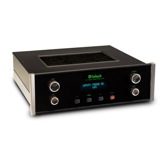
Page 31: Photos
Photos... -
Page 33: Photos
Photos, con’t... -
Page 34: Specifications
Power Requirements (High Level Inputs) High Level to Main, Output1 and 2: 15dB Field AC Voltage conversion of the C1100 is not pos- 0.05% maximun from 20Hz to 20,000Hz High Level to Rec/Fixed Output: 0dB sible. The C1100 is factory configured for one of the... -
Page 35: Packing Instruction
Customer Service Depart- 404080 #10-7/16” Flat washer ment of McIntosh Laboratory. Refer to page 3. Please see the Part List for the correct part numbers. Note: The McIntosh C1100C Controller and C1000T Tube Preamplifier use the same shipping carton. The C1100C Controller Shipping Carton also includes the “C1100C Accessories”... - Page 36 McIntosh Laboratory, Inc. 2 Chambers Street Binghamton, NY 13903 www.mcintoshlabs.com The continuous improvement of its products is the policy of McIntosh Laboratory Incorporated who reserve the right to improve design without notice. Printed in the U.S.A. McIntosh Part No. 04158801...