Table of Contents
Advertisement
Quick Links
•
Refer to Service Manual RSD6312004 for installation, operation, and troubleshooting information.
•
All safety information must be followed as provided in the Service Manual.
•
Refer to the appropriate Parts Catalog for part number information.
•
Models listed on page 3.
This manual is to be used by qualified, professionally trained HVAC technicians only. Daikin does
not assume any responsibility for property damage or personal injury due to improper service
procedures or services performed by an unqualified person.
TECHNICAL MANU
TECHNICAL MANU
TECHNICAL MANU
TECHNICAL MANU AL
TECHNICAL MANU
DP 13 SEER
R-410A Single Phase
Package Gas Units
Copyright © 2013 - 2014
AL
AL
AL
AL
RTD6312004r1
March 2014
Advertisement
Table of Contents

Related Manuals for Daikin DP13GM3004541A series


Summary of Contents for Daikin DP13GM3004541A series
- Page 1 • Models listed on page 3. RTD6312004r1 This manual is to be used by qualified, professionally trained HVAC technicians only. Daikin does not assume any responsibility for property damage or personal injury due to improper service March 2014 procedures or services performed by an unqualified person.
-
Page 2: Product Identification
WARNING Disconnect ALL power before servicing or installing this unit. Multiple power sources may be present. Failure to do so may cause property damage, personal injury or death. Daikin will not be responsible for ONLY individuals meeting (at a WARNING... - Page 3 Do not connect or use any device WARNING WARNING To prevent the risk of property WARNING that is not design certified by Daikin WARNING damage, personal injury, or death, for use with this unit. Serious prop- do not store combustible materials or use gasoline or...
-
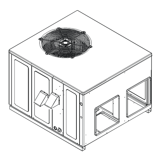
Page 4: Product Design
PRODUCT DESIGN DP13GM Package Gas Units are designed for outdoor in- Air for condensing (cooling cycle) is drawn through the out- stallations only in either residential or light commercial appli- door coil by a propeller fan, and is discharged vertically out cations and are available in 2 through 5 ton sizes. - Page 5 PRODUCT DESIGN Location and Clearances NOTE: To ensure proper condensate drainage, unit must be installed in a level position. Outside Slab Installation Rooftop Installation NOTE: Roof overhang should be no more than 36" and pro- NOTE: To ensure proper condensate drainage, unit must vision made to deflect the warm discharge air out from the be installed in a level position.
- Page 6 PRODUCT DESIGN High Altitude Derate - U.S. Installations Only (Optional) When this package unit is installed at high altitude, the ap- The gas/electric units naturally derate with altitude. High propriate High Altitude orifice kit may be installed. As alti- Altitude Derate kit may be installed if desired. tude increases, there is a natural reduction in the density of both the gas fuel and combustion air.
-
Page 7: Product Dimensions
PRODUCT DIMENSIONS UNIT DIMENSIONS FLUE EXHAUST HOOD 18 7/16 FLUE EXHAUST 1 3/8 5 1/2 7 15/16 SUCTION/LIQUID PRESSURE PORTS 2 3/4 BEHIND COMPRESSOR ACCESS PANEL COMBUSTION AIR INTAKE RETURN HEAT EXCHANGE ACCESS PANEL 4 3/4 GAS SUPPLY ENTRANCE SUPPLY CONDENSATE DRAIN CONNECTION 3/4"... - Page 8 Horizontal Jade Economizer M-Series Package Unit All Fuels, Medium Chassis H-Series All Chassis DHZECNJPGCHL Horizontal Jade Economizer M-Series Package Unit All Fuels, Large Chassis DPHFRA External Horizontal Filter Rack for Daikin M- and H-Series Package Units HA-02 High Altitude Kit LPT-03 Propane Conversion Kit Square to Round Adapter for M-Series Package Unit w/ 16"...
-
Page 9: Blower Performance Data
BLOWER PERFORMANCE DATA... -
Page 10: Specification
PACKAGE GAS SPECIFICATIONS DP13GM[24-36]***41A* DP13GM24045 DP13GM24070 DP13GM30045 DP13GM30070 DP13GM36045 41A* 41A* 41A* 41A* 41A* COOLING CAPACITY, BTUH 23,600 23,600 28,600 28,600 35,000 COOLING CAPACITY SEER / EER 13.0 / 11.0 13.0 / 11.0 13.0 / 11.0 13.0 / 11.0 13.0 / 11.0 HEATING INPUT BTUH (U.S. - Page 11 PACKAGE GAS SPECIFICATIONS DP13GM[36-48]***41A* DP13GM36070 DP13GM36090 DP13GM42070 DP13GM42090 DP13GM48070 41A* 41A* 41A* 41A* 41A* COOLING COOLING CAPACITY, BTUH 35,000 35,000 40,500 40,500 46,000 CAPACITY SEER / EER 13.0 / 11.0 13.0 / 11.0 13.0 / 11.0 13.0 / 11.0 13.0 / 11.0 HEATING INPUT BTUH (U.S.
- Page 12 PACKAGE GAS SPECIFICATIONS DP13GM[48-60]***41A* DP13GM48090 DP13GM48115 DP13GM60090 DP13GM60115 DP13GM60140 41A* 41A* 41A* 41A* 41A* COOLING COOLING CAPACITY, BTUH 46,000 46,000 57,000 57,000 57,000 CAPACITY SEER / EER 13.0 / 11.0 13.0 / 11.0 13.0 / 10.75 13.0 / 10.75 13.0 / 10.75 HEATING INPUT BTUH (U.S.
- Page 13 BLOWER PERFORMANCE DATA DP13GM[24-30]***41A* DP13GM2404541A* - Rise Range: 30° - 60° Unit MEDIUM HIGH Static WATTS AMPS RISE WATTS AMPS RISE WATTS AMPS RISE 0.67 1.02 1,190 1.67 0.65 1.00 1,140 1.62 0.63 0.97 1,080 1.58 0.61 0.94 1,025 1.54 0.58 0.90 1.38...
- Page 14 DP13GM[36-42]***41A* BLOWER PERFORMANCE DATA DP 13GM3604541A* - Rise Ra nge : 30 -60° MEDIUM HIGH Unit Static W A TTS A MPS RISE W ATTS AM PS RIS E W ATTS AMP S RIS E 1,029 1.51 1,337 2.08 1,462 2.64 1.46 1,265...
- Page 15 BLOWER PERFORMANCE DATA DP13G48***41A* DP13GM4807041A* - Rise Range: 35° - 65° F T1 HEATING SPEED T2 HEATING SPEED T3 HEATING SPEED T4 COOLING T5 COOLING E.S.P WATT RISE WATT RISE WATT RISE WATT WATT 1088 1401 1624 1704 1024 1345 1573 1655 1289...
- Page 16 DP13GM60***41A* BLOWER PERFORMANCE DATA DP13GM 6009041A* - Rise Range: 45° - 75° F T1 HEATING SPEED T 2 HEATING SPEED T3 HEATING SPEED T4 COOL ING T5 COOL ING E.S.P C FM WATT RISE W AT T RISE W ATT RISE W AT T WAT T...
- Page 17 COOLING PERFORMANCE DATA DP13GM24***41A*...
- Page 18 COOLING PERFORMANCE DATA DP13GM24***41A*...
- Page 19 COOLING PERFORMANCE DATA DP13GM30***41A*...
- Page 20 COOLING PERFORMANCE DATA DP13GM30***41A*...
- Page 21 DP13GM36***41A* COOLING PERFORMANCE DATA...
- Page 22 DP13GM36***41A* COOLING PERFORMANCE DATA...
- Page 23 COOLING PERFORMANCE DATA DP13GM42***41A*...
- Page 24 COOLING PERFORMANCE DATA DP13GM42***41A*...
- Page 25 COOLING PERFORMANCE DATA DP13GM48***41A*...
- Page 26 COOLING PERFORMANCE DATA DP13GM48***41A*...
- Page 27 COOLING PERFORMANCE DATA DP13GM60***41A*...
- Page 28 COOLING PERFORMANCE DATA DP13GM60***41A*...
-
Page 29: Performance Test
COOLING PERFORMANCE DATA PERFORMANCE TEST All data based upon listed indoor dry bulb temperature. .00 inches external static pressure on coil of outdoor section. Indoor air cubic feet per minute (CFM) as listed in the Performance Data Sheets: If conditions vary from this, results will change as follows: 1. -
Page 30: Wiring Diagrams
WIRING DIAGRAMS DP13GM[24-42]***41A* HIGH VOLTAGE! DISCONNECT ALL POWER BEFORE SERVICING OR INSTALLING THIS WARNING UNIT. MULTIPLE POWER SOURCES MAY BE PRESENT. FAILURE TO DO SO MAY CAUSE PROPERTY DAMAGE, PERSONAL INJURY OR DEATH. FOR UNITS MANUFACTURED BEFORE 3/10/14 Wiring is subject to change. Always refer to the wiring diagram on the unit for the most up-to-date wiring. - Page 31 WIRING DIAGRAMS DP13GM[24-42]***41A* HIGH VOLTAGE! DISCONNECT ALL POWER BEFORE SERVICING OR INSTALLING THIS WARNING UNIT. MULTIPLE POWER SOURCES MAY BE PRESENT. FAILURE TO DO SO MAY CAUSE PROPERTY DAMAGE, PERSONAL INJURY OR DEATH. FOR UNITS MANUFACTURED BEFORE 3/10/14 Wiring is subject to change. Always refer to the wiring diagram on the unit for the most up-to-date wiring.
- Page 32 WIRING DIAGRAMS DP13GM[24-42]***41A* HIGH VOLTAGE! DISCONNECT ALL POWER BEFORE SERVICING OR INSTALLING THIS WARNING UNIT. MULTIPLE POWER SOURCES MAY BE PRESENT. FAILURE TO DO SO MAY CAUSE PROPERTY DAMAGE, PERSONAL INJURY OR DEATH. FOR UNITS MANUFACTURED AFTER 3/9/14 COM P COM P CH O PT IONAL CH O PT IONAL...
- Page 33 WIRING DIAGRAMS DP13GM[24-42]***41A* HIGH VOLTAGE! DISCONNECT ALL POWER BEFORE SERVICING OR INSTALLING THIS WARNING UNIT. MULTIPLE POWER SOURCES MAY BE PRESENT. FAILURE TO DO SO MAY CAUSE PROPERTY DAMAGE, PERSONAL INJURY OR DEATH. FOR UNITS MANUFACTURED AFTER 3/9/14 S UPPLY V OLTAG E S UPPLY V OLTAG E COMPO NENT LE GE ND COMPO NENT LE GE ND...
- Page 34 WIRING DIAGRAMS DP13GM[48-60]***41A* HIGH VOLTAGE! DISCONNECT ALL POWER BEFORE SERVICING OR INSTALLING THIS WARNING UNIT. MULTIPLE POWER SOURCES MAY BE PRESENT. FAILURE TO DO SO MAY CAUSE PROPERTY DAMAGE, PERSONAL INJURY OR DEATH. FOR UNITS MANUFACTURED BEFORE 3/10/14 Wiring is subject to change. Always refer to the wiring diagram on the unit for the most up-to-date wiring.
- Page 35 WIRING DIAGRAMS DP13GM[48-60]***41A* HIGH VOLTAGE! DISCONNECT ALL POWER BEFORE SERVICING OR INSTALLING THIS WARNING UNIT. MULTIPLE POWER SOURCES MAY BE PRESENT. FAILURE TO DO SO MAY CAUSE PROPERTY DAMAGE, PERSONAL INJURY OR DEATH. FOR UNITS MANUFACTURED BEFORE 3/10/14 Wiring is subject to change. Always refer to the wiring diagram on the unit for the most up-to-date wiring.
- Page 36 WIRING DIAGRAMS DP13GM[48-60]***41A* HIGH VOLTAGE! DISCONNECT ALL POWER BEFORE SERVICING OR INSTALLING THIS WARNING UNIT. MULTIPLE POWER SOURCES MAY BE PRESENT. FAILURE TO DO SO MAY CAUSE PROPERTY DAMAGE, PERSONAL INJURY OR DEATH. FOR UNITS MANUFACTURED AFTER 3/9/14 COMP CH OPTIONAL CONNECTED AT L1, L2 CH OPTIONAL NOTE 3...
- Page 37 WIRING DIAGRAMS DP13GM[48-60]***41A* HIGH VOLTAGE! DISCONNECT ALL POWER BEFORE SERVICING OR INSTALLING THIS WARNING UNIT. MULTIPLE POWER SOURCES MAY BE PRESENT. FAILURE TO DO SO MAY CAUSE PROPERTY DAMAGE, PERSONAL INJURY OR DEATH. FOR UNITS MANUFACTURED AFTER 3/9/14 CO MPO NE NT LEGE ND S UPPLY VO LTA GE AUXILLARY LIM IT SW ITCH 208-230 /1/60...