Yamaha CRX-140 Service Manual
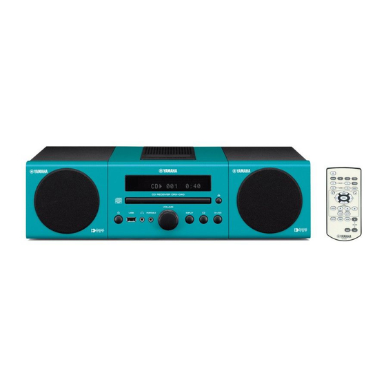
Micro component system
speaker
Hide thumbs
Also See for CRX-140:
- Owner's manual (136 pages) ,
- Service manual (100 pages) ,
- Owner's manual (26 pages)
Table of Contents
Advertisement
MICRO COMPONENT SYSTEM
Crx-040/Crx-140/
The MCR-040 consists of the CRX-040 and NS-BP80.
The MCR-140 consists of the CRX-140 and NS-BP80.
MCR-040 は、CRX-040 および NS-BP80 で構成されています。
MCR-140 は、CRX-140 および NS-BP80 で構成されています。
This manual has been provided for the use of authorized YAMAHA Retailers and their service personnel.
It has been assumed that basic service procedures inherent to the industry, and more specifi cally YAMAHA Products, are already known
and understood by the users, and have therefore not been restated.
WARNING:
IMPORTANT:
The data provided is believed to be accurate and applicable to the unit(s) indicated on the cover. The research, engineering, and service
departments of YAMAHA are continually striving to improve YAMAHA products. Modifications are, therefore, inevitable and
specifi cations are subject to change without notice or obligation to retrofi t. Should any discrepancy appear to exist, please contact the
distributor's Service Division.
WARNING:
IMPORTANT:
■ CONTENTS
To Service Personnel ............................................2
SYSTEM COMPOSITION / システム構成 .......................6
Front Panels .........................................................7–9
Rear Panels ....................................................... 10–13
Remote Control Panels ..................................... 14
SPECIFICATIONS / 参考仕様 ................................. 15–17
Internal View .......................................................... 18
DISASSEMBLY PROCEDURES / 分解手順 ........... 19–22
ファームウェアのアップデート ............................23–33
1 0 1 1 5 7
CD RECEIVER/
SERVICE MANUAL
IMPORTANT NOTICE
Failure to follow appropriate service and safety procedures when servicing this product may result in personal injury,
destruction of expensive components, and failure of the product to perform as specifi ed. For these reasons, we advise
all YAMAHA product owners that any service required should be performed by an authorized YAMAHA Retailer or
the appointed service representative.
The presentation or sale of this manual to any individual or fi rm does not constitute authorization, certifi cation or
recognition of any applicable technical capabilities, or establish a principle-agent relationship of any form.
Static discharges can destroy expensive components. Discharge any static electricity your body may have
accumulated by grounding yourself to the ground buss in the unit (heavy gauge black wires connect to this buss).
Turn the unit OFF during disassembly and part replacement. Recheck all work before you apply power to the unit.
SELF-DIAGNOSTIC FUNCTION /
ダイアグ(自己診断機能) .....................................34–48
Display Data .............................................................49
Ic Data ...................................................................50–54
Block Diagram ........................................................55
Printed Circuit Boards .................................56–65
Pin Connection Diagrams ...................................66
Schematic Diagrams ....................................... 67–74
Replacement Parts List ................................75–90
Remote Control ...............................................91–92
USING USEFUL FUNCTIONS / 便利な機能 ...........93–98
Copyright © 2009
This manual is copyrighted by YAMAHA and may not be copied or
redistributed either in print or electronically without permission.
MCR-040/MCR-140
All rights reserved.
SPEAKER
NS-BP80
P.O.Box 1, Hamamatsu, Japan
'09.12
Advertisement
Table of Contents

Related Manuals for Yamaha CRX-140


Summary of Contents for Yamaha CRX-140
- Page 1 This manual has been provided for the use of authorized YAMAHA Retailers and their service personnel. It has been assumed that basic service procedures inherent to the industry, and more specifi cally YAMAHA Products, are already known and understood by the users, and have therefore not been restated.
-
Page 2: Crx-040/Crx
CRX-040/CRX-140/NS-BP80 ■ TO SERVICE PERSONNEL AC LEAKAGE WALL EQUIPMENT TESTER OR 1. Critical Components Information OUTLET UNDER TEST EQUIVALENT Components having special characteristics are marked and must be replaced with parts having specifications equal to those originally installed. 2. Leakage Current Measurement (For 120V Models Only) - Page 3 CRX-040/CRX-140/NS-BP80 WARNING: Lithium batteries CAUTION 注意 Danger of explosion if battery is incorrectly replaced. 正しい電池と交換しないと爆発が起きるおそれがありま Replace only with the same or equivalent type. す。 同一型名または同等品以外の電池とは絶対に交換しない ようにしてください。 WARNING: ADVARSEL! Lithium batteries are dangerous because they can be exploded by improper handling. Observe the Lithiumbatteri –Eksplosionsfare ved fejlagtig håndtering.
- Page 4 CRX-040/CRX-140/NS-BP80 Laser Diode Properties Type: Semiconductor laser GaAs/GaAlAs Wavelength: 780 nm Output power: 10 mW Warning for power supply The primary side of the power supply carries live mains voltage when the player is connected to the mains even when the player is switched off ! This primary area is not shielded so it is possible to accidentally touch copper tracks and/or components when servicing the player.
- Page 5 CRX-040/CRX-140/NS-BP80 ■ PREVENTION OF ELECTROSTATIC DISCHARGE Some semiconductor (solid state) devices can be damaged easily by static electricity. Such components commonly are called Electrostatically Sensitive (ES) Devices. Examples of typical ES devices are integrated circuits and some field-effect transistors and semiconductor “chip” components. The following techniques should be used to help reduce the incidence of component damage caused by electrostatic discharge (ESD).
- Page 6 CRX-040/CRX-140/NS-BP80 ■ SYSTEM COMPOSITION / システム構成 The MCR-040 consists of the CRX-040 and NS-BP80. The MCR-140 consists of the CRX-140 and NS-BP80. MCR-040 は、CRX-040 および NS-BP80 で構成されています。 MCR-140 は、CRX-140 および NS-BP80 で構成されています。 MCR-040 ▼ NS-BP80 ▼ CRX-040 ▼ NS-BP80 MCR-140 ▼...
- Page 7 CRX-040/CRX-140/NS-BP80 ■ FRONT PANELS CRX-040 CRX-140 U, T, K, A, B, G, L, V, J models U, T, A, B, G, L, V, J models...
- Page 8 CRX-040/CRX-140/NS-BP80 NS-BP80 U, T, K, A, B, G, L, V, J models...
- Page 9 CRX-040/CRX-140/NS-BP80 ● Color Variations / カラーバリエーション OR : Orange color / オレンジ WH : White color / ホワイト : Light Gray color / ライトグレー DG : Dark Gray color / ダークグレー : Light Blue color / ライトブルー : Dark Blue color / ダークブルー...
- Page 10 CRX-040/CRX-140/NS-BP80 ■ REAR PANELS CRX-040 U model T model K model A model B model G model...
- Page 11 CRX-040/CRX-140/NS-BP80 CRX-040 L model V model J model...
- Page 12 CRX-040/CRX-140/NS-BP80 CRX-140 U model T model A model B model G model L model...
- Page 13 CRX-040/CRX-140/NS-BP80 CRX-140 V model J model NS-BP80 U, T, K, A, B, G, L, V, J models...
- Page 14 CRX-040/CRX-140/NS-BP80 ■ REMOTE CONTROL PANELS CRX-040 CRX-140 U, T, K, A, B, G, L, V models J model...
-
Page 15: Specifications
Maximum Input Signal Level / 最大許容入力 (1 kHz, 0.5 % THD) ■ Speaker Section / スピーカー部 (NS-BP80) PORTABLE ..............2.5 V or more Type / 型式 .... Advanced Yamaha Active Servo Technology Output Level/Output Impedance / 出力電圧/出力インピーダンス (1 kHz, 450 mV, 32 ohms) アドバンスド... - Page 16 WH (White color) .......U, T, K, A, B, G, L, V, J models Advanced Yamaha Active Servo Technology II Advanced Yamaha Active Servo Technology is a unique system to let the LG (Light Gray color) ......U, T, K, A, B, G, L, V, J models speaker unit have a perfectly linear motion by the speaker and amplifier DG (Dark Gray color) ......U, T, K, A, B, G, L, V, J models...
- Page 17 CRX-040/CRX-140/NS-BP80 • DIMENSIONS / 寸法図 CRX-040 CRX-140 NS-BP80 Top view Top view 2.5 (1/8") 5 (1/4") 17 (5/8") 5 (1/4") 2 (1/8") Front view Front view 6 (1/4") 4 (1/8") 155 (6-1/8") 102 (4") 180 (7-1/4") 120 (4-3/4") Unit: mm (inch) Unit: mm (inch) 単位...
- Page 18 FM TUNER (U, T, K, G, L, V, J models) MAIN (1) P.C.B. SUB (3) P.C.B. (L, V models) SUB (2) P.C.B. LOADER MECHANISM UNIT CONNECTOR (2) P.C.B. (CRX-140) MAIN (3) P.C.B. (CRX-040) Top view CONNECTOR (1) P.C.B. (CRX-140) SUB (1) P.C.B.
-
Page 19: Table Of Contents
Remove CB801-802. (Fig. 1) CB702 ∼ 703 を外します。 (Fig. 1) (CRX-040) Remove CB702-703. (Fig. 1) (CRX-040) g. CB602 ∼ 604 を外します。 (Fig. 1) (CRX-140) g. Remove CB602-604. (Fig. 1) (CRX-140) h. フック 2 箇所を外し、フロントパネルユニットを取り Release 2 hooks, and remove the front panel unit. -
Page 20: Table Of Contents
CRX-040/CRX-140/NS-BP80 2. Removal of Loader Mechanism Unit 2. ローダーメカユニットの外し方 Remove 4 screws ( ④ ). (Fig. 2) a. ④ のネジ 4 本を外します。 (Fig. 2) b. Remove CB502 and W501. (Fig. 2) b. CB502、W501 を外します。 (Fig. 2) Unlock and remove CB4 and ground the terminal side c. -
Page 21: Sub (1) P.c.b
CRX-040/CRX-140/NS-BP80 CRX-040 When checking the P.C.B.s: P.C.B. をチェックする場合には: • Spread the rubber sheet and the cloth. Then place ・ ゴムシートと布を敷き、 その上に本機を置いてチェッ this unit on the cloth and check it. (Fig. 3) クします。 (Fig. 3) • When connecting the flexible flat cable, be careful ・... -
Page 22: Loader Mechanism Unit
CRX-040/CRX-140/NS-BP80 CRX-140 When checking the P.C.B.s: P.C.B. をチェックする場合には: • Spread the rubber sheet and the cloth. Then place ・ ゴムシートと布を敷き、 その上に本機を置いてチェッ this unit on the cloth and check it. (Fig. 4) クします。 (Fig. 4) • When connecting the flexible flat cable, be careful ・... -
Page 23: Updating Firmware
CRX-040/CRX-140/NS-BP80 ■ UPDATING FIRMWARE / ファームウェアのアップデート When the following parts are replaced, the firmware must 下記の部品を交換した場合、ファームウェアを最新バー be updated to the latest version. ジョンにアップデートする必要があります。 Replaced Parts Firmware Update method Model 交換した部品 ファームウェア アップデートの方法 モデル名 MAIN P.C.B. Main microprocessor firmware Updating the main microprocessor firmware... - Page 24 CRX-040/CRX-140/NS-BP80 ● Required tools ● 必要なツール • Firmware downloader program ..FlashSta.exe ・ プログラム書き込み用プログラム ..FlashSta.exe • Firmware ・ ファームウェア Main microprocessor firmware (CRX-040/CRX-140) メインマイコンファームウェア(CRX-040/CRX-140) ..........CRX_x40_xxxx.mot .............CRX_x40_xxxx.mot CRX_x40_xxx.id CRX_x40_xxx.id Wireless module firmware (CRX-140) ワイヤレスモジュールファームウェア(CRX-140) ......... uaw_firmup_xxxx.mot ............uaw_fi rmup_xxxx.mot uaw_firmup_xxxx.id...
- Page 25 CRX-040/CRX-140/NS-BP80 Updating the main microprocessor firmware メインマイコンファームウェアのアップデート ● Connection ● 接続 Disconnect the power cable of this unit from the ※ 本機の電源コードを AC コンセントから抜いてく AC outlet. ださい。 1. Set the switch (SW7) of RS232C conversion 1. RS232C 変 換 ア ダ プ タ ー の ス イ ッ チ(SW7) を...
- Page 26 CRX-040/CRX-140/NS-BP80 2. Start up FlashSta.exe. 2. FlashSta.exe を起動します。 The screen appears as shown below. (Fig. 2) 下記の画面が表示されます。 (Fig. 2) 3. Select the data to be transmitted and port. (Fig. 2) 3. 送信データ、ポートを選択します。 (Fig. 2) • Select Program ・ Select Program Select Internal flash memory.
- Page 27 CRX-040/CRX-140/NS-BP80 5. Click [Setting], and set the baud rate. (Fig. 4) 5. [Setting]をクリックし、通信速度の設定を行い ます。 (Fig. 4) Reduce the baud rate if a transmission error ※ 送信エラーが多発する場合は、通信速度を下 occurs frequently. げてください。 115200 Fig. 4 6. Click [E.P.R.], then the “Erase” screen appears.
- Page 28 CRX-040/CRX-140/NS-BP80 8. When writing of the firmware is completed, the 8. ファームウェアの書き込みが完了すると、以下の screen appears as shown below. (Fig. 6) 画面が表示されます。 (Fig. 6) Click [OK]. (Fig. 6) [OK]をクリックします。 (Fig. 6) 9. Click [Exit] to end FlashSta.exe. (Fig. 6) 9. [Exit]をクリックして FlashSta.exe を終了します。...
- Page 29 CRX-040/CRX-140/NS-BP80 Updating the Wireless Module Firmware and ワイヤレスモジュールファームウエアと the AirWired microprocessor Firmware AirWired マイコンファームウエアのアップデート ● Connection ● 接続 Disconnect the power cable of this unit from the ※ 本機の電源コードを AC コンセントから抜いてく AC outlet. ださい。 • Remove the side cover R. (See “DISASSEMBLY ・...
- Page 30 CRX-040/CRX-140/NS-BP80 ● Operation procedure ● 操作方法 CAUTION: Perform “Writing the wireless module 注意: 先に「 ワイヤレスモジュールファームウェ firmware” 1st and “Writing the AirWired アの書き込み」を、次に「 AirWired マイ Microprocessor Firmware” 2nd, otherwise コンファームウェアの書き込み」 を行います。 this unit will not operate properly. そうしないと、本機は正常に動作しません。 Perform the following procedures.
- Page 31 CRX-040/CRX-140/NS-BP80 If the “Timeout” error screen appears, press the ※ も し タ イ ム ア ウ ト エ ラ ー が 表 示 さ れ た 場 合、 “reset switch (SW3)” of the RS232C conversion RS232C 変 換 ア ダ プ タ ー の リ セ ッ ト ス イ ッ チ...
- Page 32 CRX-040/CRX-140/NS-BP80 7. Click [Setting], and set the baud rate. (Fig. 5) 7. [Setting]をクリックし、通信速度の設定を行い ます。 (Fig. 5) Reduce the baud rate if a transmission error ※ 送信エラーが多発する場合は、通信速度を下 occurs frequently. げてください。 57600 Fig. 5 8. Click [E.P.R.], then the “Erase” screen appears.
- Page 33 CRX-040/CRX-140/NS-BP80 10. When writing of the firmware is completed, the 10. ファームウェアの書き込みが完了すると、以下の screen appears as shown below. (Fig. 7) 画面が表示されます。 (Fig. 7) Click [OK]. (Fig. 7) [OK]をクリックします。 (Fig. 7) 11. Click [Exit] to end FlashSta.exe. (Fig. 7) 11. [Exit]をクリックして FlashSta.exe を終了します。...
- Page 34 CRX-040/CRX-140/NS-BP80 ■ SELF-DIAGNOSTIC FUNCTION / ダイアグ(自己診断機能) There are 12 main menu items, each of which has sub- メ イ ン メ ニ ュ ー は 12 個 あ り、 そ の そ れ ぞ れ に サ ブ メ menu items.
- Page 35 CRX-040/CRX-140/NS-BP80 ● Starting Self-Diagnostic Function ● ダイアグの起動 While pressing the “INPUT” and “ ” (Play/Pause) keys INPUT と (再生 / 一時停止) キーを押しながら (ス of this unit as shown in the figure below, press the “ ” タンバイ / オン)キーを押して電源を入れます。 (Standby/On) key to turn on the power.
- Page 36 CRX-040/CRX-140/NS-BP80 CAUTION! 注意! Using this product with the protection function disabled プロテクションを解除した状態でのダイアグモードは、 may cause further damage to itself. Use special care 危険な状態でもプロテクションが作動しないため、動作 when using this mode. させると、機器を破壊することがあります。このモード を使用する場合は十分注意してください。 ● Canceling Self-diagnostic function ● ダイアグの解除 Before canceling self-diagnostic function, execute ダイアグを解除する前に、メインメニュー No. C の...
- Page 37 CRX-040/CRX-140/NS-BP80 ● History of protection function ● プロテクションの履歴 When the protection function has worked, its history is プロテクションが働いた場合、履歴をバックアップして stored in memory with a backup. Even if no abnormality 記憶しています。修理のときに異常が認められなくても、 is noted while servicing the unit, an abnormality which バックアップが残っていれば、お客様のところで起きた has occurred previously can be defined as long as the 異常を区別できます。...
- Page 38 CRX-040/CRX-140/NS-BP80 ● Functions in Self-Diagnostic Function ● ダイアグ中の機能 mode In addition to the self-diagnostic function menu items, ダイアグメニューの他に、以下の機能が動作します。 functions listed below are available. ・ 電源オン/オフ • Power on/off ・ マスターボリューム • Master volume ・ ミュート • Muting ・ ディスクトレイの開閉 •...
- Page 39 The firmware version of AirWired microprocessor (IC1 of the AW-CARD P.C.B.) is displayed. サブウーファーチャンネルからテストノイズが出力されます。 1-6 AirWired WIRELESS MODULE (ADLIB2) VERSION (CRX-140) 1 - 6 A D L I B 2 : - - - The firmware version of AirWired wireless module (IC5 of the AW-CARD P.C.B.) is displayed.
- Page 40 CRX-040/CRX-140/NS-BP80 2. AUDIO TEST 2. AUDIO TEST This menu is used to select the input souse. 入力ソースを選択します。 2-1 iPod 2 - 1 A U D I O i P o d The iPod is selected. iPod が選択されます。 2-2 PRTBL (PORTABLE) 2 - 2 A U D I O P R T B L The PORTABLE is selected.
- Page 41 CRX-040/CRX-140/NS-BP80 3. FL DISPLAY CHECK 3. FL DISPLAY CHECK This menu is used to check the FL display section. FL 表示部の動作を確認します。 Using the sub-menu, the display condition changes サブメニュー操作により、表示状態が以下のように as shown below. 変わります。 3-1 Initial display / 初期表示 3 - 1 C H E C K 3-2 ALL SEGMENTS OFF / 全セグメン...
- Page 42 CRX-040/CRX-140/NS-BP80 4. iPod (CRX-040) 4. iPod(CRX-040) This menu is used to check the connecting condition iPod 端子の接続状態を確認します。 of the iPod terminal. iPod を本機の iPod 端子に接続します。 Before starting check, connect the iPod to the iPod terminal of this unit. 4 i P o d O K : N N Y OK: All Y / すべてY...
- Page 43 CRX-040/CRX-140/NS-BP80 6. CD CHECK 6. CD CHECK This menu is used to check operation of the loader ローダーメカユニットの動作を確認します。 mechanism unit. サブメニュー選択後、 (再生 / 一時停止)を押 Select sub-menu and press the “ ” (Play/Pause) して動作モードを切り替えます。 key to change operation mode. 6-1 LASER DIODE CHECK 6 - 1 C D L D : O F F ON/OFF of the laser diode is checked.
- Page 44 CRX-040/CRX-140/NS-BP80 AD DATA CHECK 7. AD DATA CHECK This menu is used to display the A/D conversion 本機パネルキー、プロテクションなどを検出してい value of the microprocessor which detects panel keys るメインマイコンの A/D 変換の値を、サブメニュー of this unit and protection functions by using the sub- で表示します。...
- Page 45 メインマイコン(IC267)の 92 ピン(MODEL) microprocessor IC267 is displayed. の電圧値を表示します。 CRX-040: 0 to 50 CRX-040:0 ∼ 50 CRX-140: 205 to 255 CRX-140:205 ∼ 255 (Reference voltage: 3.3V=255) (基準電圧:3.3 V = 255) 7 - 4 M O D E L : 2 4 8...
- Page 46 モデル名、仕向け先が表示されます。 destination. 9-1 MODEL 9 - 1 C R X - 1 4 0 The model name (CRX-040/CRX-140) is displayed. モデル名(CRX-040/CRX-140)が表示されます。 9-2 DESTINATION 9 - 2 D E S T : G The destination (U, A, G, B, TKAL, J) is displayed.
- Page 47 CRX-040/CRX-140/NS-BP80 B. AirWired UPGRADE (CRX-140) B. AirWired UPGRADE (CRX-140) This menu is used to select the AirWired UPGRADE AirWired UPGRADE メニューを選択します。 menu. B-1 AirWired UPGRADE MENU B - 1 A W U P G R A D E The “AirWired UPGRADE” menu is displayed.
- Page 48 CRX-040/CRX-140/NS-BP80 C. FACTORY PRESET C. FACTORY PRESET This menu is used to reserve/inhibit initialization of the バックアップ IC の初期化を予約/禁止します。 back-up IC. INIT INHI (Initialization inhibited) / INIT INHI(初期化禁止) C - 1 P R E S E T I N H Initialization of the back-up IC is not executed.
- Page 49 CRX-040/CRX-140/NS-BP80 ■ DISPLAY DATA ● V801 : 16-BT-133GNK (SUB P.C.B.) PATTERN AREA ● PIN CONNECTION Pin No. Connection Pin No. Connection Note : 1) F1, F2 ..Filament 2) NP ..No pin 3) NX ..No extended Pin 4) 1G − 16G ..Grid 5) NC ..
- Page 50 CRX-040/CRX-140/NS-BP80 ■ IC DATA IC267: R5F3640DNFA CPU (MAIN P.C.B.) Single-chip 16-bit CMOS microprocessor Port P0 Port P1 Port P2 Port P3 Port P4 Port P5 VCC2 ports Internal peripheral functions UART or clock synchronous Clock generation circuit serial I/O Timer (16-bit)
- Page 51 CRX-040/CRX-140/NS-BP80 Function Port Name Name Detail of Function (P.C.B.) 1 P96/ANEX1/SOUT4 TUaFL_MOSI SPI for FL control/TUNER control 2 P95/ANEX0/CLK4 TUaFL_SCK SPI for FL control/TUNER control Unused / Buffer executed before uCOM input CRX-040 Reset signal of AW module / Buffer executed before uCOM input...
- Page 52 CRX-040/CRX-140/NS-BP80 Function Port Name Name Detail of Function (P.C.B.) P70/TXD2/SDA2/ DAB_SDA B model TA0out 31 P67/TXD1/SDA1 TXD1 32 P66/RXD1/SCL1 RXD1 33 P65/CLK1 CLK1 P64/CTS1/RTS1/ BUSY CTS0/CLKS1 35 P63/TXD0/SDA0 ASEL_SDA 36 P62/RXD0/SCL0 ASEL_SCL 37 P61/CLK0 USB_DET_OFF MUTE control signal of D-AMP...
- Page 53 CRX-040/CRX-140/NS-BP80 Function Port Name Name Detail of Function (P.C.B.) Power on SW of OPE circuit board 67 P25/A5/AN25/INT7 P_SW 0: Power on SW off 1: Power on SW pressed Detection of USB current / This function is valid only in Standby and Sleep modes and invalid when power is on.
- Page 54 Port Name Name Detail of Function (P.C.B.) 91 P105/AN5/KI1 PS3_PRT Power source protection 3 92 P104/AN4/KI0 MODEL Identification of models (CRX-040, CRX-140) 93 P103/AN3 DEST Identification of destination 94 P102/AN2 PS2_PRT Power source protection 2 95 P101/AN1 PS1_PRT Power source protection 1...
-
Page 55: Block Diagram
CRX-040/CRX-140/NS-BP80 ■ BLOCK DIAGRAM CONNECTOR SUB (1) → → SCHEMATIC DIAGRAM SCHEMATIC DIAGRAM VOLUME iPod BOARD CONNECT BOARD Phones Portable FL/Driver CRX-040 CRX-140 V801/IC801 Stand by/on +3.3D 35mA iPod -21V 30mA -21V KEY0 +3.3M INPUT +3.3D STOP +14_FL PLAY/PAUSE OPEN/CLOSE... - Page 56 CRX-040/CRX-140/NS-BP80 POINT D 1 / IC267 (99 pin, +3.3M), 2 / IC267 (12 pin, nSYS_RST) ■ PRINTED CIRCUIT BOARDS Circuit No. U, T, K, G, L, V, J A, B C277, C283 R264 R423 C275, C285 MAIN (1) P.C.B. (Side A)
- Page 57 CRX-040/CRX-140/NS-BP80 POINT D 1 / IC267 (99 pin, +3.3M), 2 / IC267 (12 pin, nSYS_RST) MAIN (1) P.C.B. (Side B) IC267 IC267 (+3.3M) (+3.3M) IC267 IC267 (nSYS_RST) (nSYS_RST) POWER ON POWER OFF POWER ON POINT A XL251 (Pin 13 of IC251)
- Page 58 CRX-040/CRX-140/NS-BP80 MAIN (2) P.C.B. MAIN (3) P.C.B. (Side A) (Side A) A, B models IPAP_DET IPD_ACC_EN IPD_MOSI IPD_MISO nIPD_DET DGND IGND IGND IC901 MAIN (2) (W252) CB902 DAB MODULE DOCK IC902 CB701 +16D DGND DAB_SCL DAB_SDA nDAB_RST DAB_L DAB_AGND DAB_R...
- Page 59 CRX-040/CRX-140/NS-BP80 ■ PRINTED CIRCUIT BOARDS MAIN (2) P.C.B. MAIN (3) P.C.B. (Side B) (Side B) A, B models • Semiconductor Location Ref no. Location D701 D702 D703 Q701 Q702...
- Page 60 CRX-040/CRX-140/NS-BP80 SUB (1) P.C.B. (Side A) -21V +14_FL +3.3M +3.DGND TUaFL_SCK FL_CLOCK LINE_L nFL_CS AGND +3.3D LINE_R TUaFL_MOSI HP_DET nFL_RST HP_R REMOTE HP_AGND DGND HP_L KEY0 P_SW VOL_RA USB_D- VOL_RB USB_D+ UGND UGND SW804 MAIN (1) (W256) MAIN (1) (W254)
- Page 61 CRX-040/CRX-140/NS-BP80 SUB (1) P.C.B. (Side B) 33 32 64 1 • Semiconductor Location Ref no. Location D801 D802 D803 D804 D813 D814 D815 D816 IC801 Q801 Q805...
- Page 62 CRX-040/CRX-140/NS-BP80 SUB (2) P.C.B. SUB (3) P.C.B. (Side A) (Side A) L, V models VOLTAGE SELECTOR POWER TRANSFORMER MAIN (1) (CB103) AC-28VN AC-28VL AC+10IN AC+10IL L, V models ACAMPVCCN ACAMPVCCN ACAMPGNDL ACAMPGNDL AC+16VN AC+16VL DGND AC_IN T, K models PRY_CTRL...
- Page 63 CRX-040/CRX-140/NS-BP80 SUB (2) P.C.B. SUB (3) P.C.B. (Side B) (Side B) L, V models • Semiconductor Location Ref no. Location...
- Page 64 CRX-040/CRX-140/NS-BP80 CONNECTOR (1) P.C.B. CONNECTOR (2) P.C.B. (Side A) (Side A) MAIN (2) MAIN (2) (W253) (W252) MAIN (2) (W251) Writing port CB603 CB602 CB604 CB606 CB605 IGND W601 IC601 MAIN (2) (CB902)
- Page 65 CRX-040/CRX-140/NS-BP80 CONNECTOR (1) P.C.B. CONNECTOR (2) P.C.B. (Side B) (Side B) • Semiconductor Location Ref no. Location D601 IC601...
- Page 66 HZU3.3B2 TRF-E AN41010A-VF BA00BC0WFP-E2 BD9870FPS-E2 LC72725KM-UY-TLM-E M12L16161A-7TG (CRX-140) HZU5.1B3 TRF-E HZU6.8B2 TRF-E HZU8.2B2 TRF-E Anode Anode HZU10B1 TRF-E (CRX-140) Anode HZU12B2 TRF-E – Cathode Cathode + AC Cathode RB160M-60 TR RSB6.8S 6.8V (CRX-040) S1NB60 1.0A 600V UDZS5.6B TE-17 5.6V UDZ6.8B 6.8V...
- Page 67 <7.8> 12.0 19.7 <19.5> <8.3> IC105 12.0 19.7 <19.5> < > the voltage is CRX-140. < >内の電圧はCRX-140です。 CRX-140 IC103, 104, 107: BD9870FPS-E2 High stand voltage 1 channel step-down switching regulator IC105: NJM7812FA IC106: NJM431U IC101: R5523N001A-TR-F IC102, 108: RP102N331D-TR-F Adjustable precision shunt regulator...
- Page 68 /2dB step Vdda Vddd RDS-ID RDS-ID/ <-21.3> TEST TEST DETECT READY Vssa Vssd Volume < > the voltage is CRX-140. VOLINR FLOUT MODE 0~87dB,-∞ TEST XOUT < >内の電圧はCRX-140です。 CRX-140 CRX-040 IC260: MFI341S2164 IC digital POINT B XL252 (Pin 15 of IC267) POINT C XL253 (Pin 11 of IC267) POINT D 1 / IC267 (99 pin, +3.3M), 2 / IC267 (12 pin, nSYS_RST)
- Page 69 CB502 <3.6> To Loader mechanism unit <3.5> <3.3> W501 (Writing port) To Loader mechanism unit < > the voltage is CRX-140. CD IN < >内の電圧はCRX-140です。 IC501: AN41010A-VF 5-ch. linear driver IC for CD and DVD player CRX-040 CRX-140 [Sled] [Spindle]...
- Page 70 CRX-040/CRX-140/NS-BP80 MAIN 4/5 MAIN (2) A, B models IC902 IC901 CB902 To DAB module CB901 Page 68 to MAIN (1)_CB252 IC902: R1172H121D-T1-F IC901: BD9870FPS-E2 High stand voltage 1 channel step-down switching regulator CMOS-based positive-voltage regulator IC VREF PWM COMP DRIVER...
- Page 71 CRX-040/CRX-140/NS-BP80 MAIN 5/5 MAIN (3) CRX-040 CB703 Page 68 to MAIN (1)_W255 CB702 Page 68 to MAIN (1)_W252 DOCK No replacement part available. サービス部品供給なし ★ All voltages are measured with a 10MΩ/V DC electronic voltmeter. ● 電圧は、内部抵抗 10MΩの電圧計で測定したものです。 ★ Components having special characteristics are marked and must be replaced ●...
- Page 72 <6.9> 12.9 <AC9.6> <3.2> <3.3> <3.1> < > the voltage is CRX-140. < >内の電圧はCRX-140です。 ★ All voltages are measured with a 10MΩ/V DC electronic voltmeter. ● 電圧は、内部抵抗 10MΩの電圧計で測定したものです。 ★ Components having special characteristics are marked and must be replaced ●...
- Page 73 VOLUME Page 68 to MAIN (1)_W254 JK801 PHONES < > the voltage is CRX-140. < >内の電圧はCRX-140です。 ★ All voltages are measured with a 10MΩ/V DC electronic voltmeter. ● 電圧は、内部抵抗 10MΩの電圧計で測定したものです。 ★ Components having special characteristics are marked and must be replaced ●...
- Page 74 CRX-040/CRX-140/NS-BP80 CONNECTOR CRX-140 Page 68 to MAIN (1)_W251 CONNECTOR (1) CB606 IPOD IN Writing port Page 70 IC601 to MAIN (2)_CB902 (A, B models) CB601 IC601: BA00BC0WFP-E2 1.0 A low-dropout voltage regulator with shut down switch GND (FIN) Page 68...
-
Page 75: Replacement Parts List
CRX-040/CRX-140/NS-BP80 ■ REPLACEMENT PARTS LIST • ELECTRICAL COMPONENT PARTS WARNING ● Components having special characteristics are marked and must be replaced with parts having specifications equal to those originally installed. ● 印のある部分は、安全確保部品を示しています。部品の交換が必要な場合、パーツリストに記載されている部品を使用し てください。 ● 部品価格ランクは、予告なく変更することがあります。 ABBREVIATIONS IN THIS LIST ARE AS FOLLOWS: C.A.EL.CHP... - Page 76 CRX-040/CRX-140/NS-BP80 CRX-040 CRX-140 P.C.B. MAIN Ref No. Part No. Description Remarks Markets 部 品 名 ランク WS475400 P.C.B. MAIN CRX140 PCB MAIN WS476000 P.C.B. MAIN CRX040 PCB MAIN WS475500 P.C.B. MAIN CRX140 PCB MAIN WS476100 P.C.B. MAIN CRX040 PCB MAIN WS475600 P.C.B. MAIN CRX140 PCB MAIN WS476200 P.C.B.
- Page 77 CRX-040/CRX-140/NS-BP80 CRX-040 CRX-140 P.C.B. MAIN Ref No. Part No. Description Remarks Markets 部 品 名 ランク C150 US062100 C.CE.CHP 100pF 50V B チップセラコン C151 UU249100 C.EL 1000uF ケミコン C154 UR818470 C.EL 470uF 6.3V ケミコン C155 US065100 C.CE.CHP 0.1uF 50V B チップセラコン C156-157 US163100 C.CE.CHP...
- Page 78 CRX-040/CRX-140/NS-BP80 CRX-040 CRX-140 P.C.B. MAIN Ref No. Part No. Description Remarks Markets 部 品 名 ランク C266 US135100 C.CE.CHP 0.1uF JUTGLV チップセラコン C267-268 US062100 C.CE.CHP 100pF 50V B チップセラコン C269 UR837100 C.EL 10uF JUTGLV ケミコン C270-273 US062100 C.CE.CHP 100pF 50V B JUTGLV チップセラコン...
- Page 79 CRX-040/CRX-140/NS-BP80 CRX-040 CRX-140 P.C.B. MAIN Ref No. Part No. Description Remarks Markets 部 品 名 ランク C359 US135100 C.CE.CHP 0.1uF チップセラコン C360 US061270 C.CE.CHP 27pF 50V B チップセラコン C361 US061180 C.CE.CHP 18pF 50V B チップセラコン C362 US062100 C.CE.CHP 100pF 50V B チップセラコン...
- Page 80 CRX-040/CRX-140/NS-BP80 CRX-040 CRX-140 P.C.B. MAIN Ref No. Part No. Description Remarks Markets 部 品 名 ランク C501-502 US135100 C.CE.CHP 0.1uF チップセラコン * C503-504 WP882000 C.CE.CHP 10uF 6.3V チップセラコン C507 US163100 C.CE.CHP 1000pF チップセラコン C508 UR817470 C.EL 47uF 6.3V ケミコン C509 UR838100 C.EL 100uF ケミコン...
- Page 81 CRX-040/CRX-140/NS-BP80 CRX-040 CRX-140 P.C.B. MAIN Ref No. Part No. Description Remarks Markets 部 品 名 ランク C578 US163100 C.CE.CHP 1000pF チップセラコン C579-580 US135100 C.CE.CHP 0.1uF チップセラコン C581 US163100 C.CE.CHP 1000pF チップセラコン C582 US135100 C.CE.CHP 0.1uF チップセラコン C583-585 UR817470 C.EL 47uF 6.3V ケミコン...
- Page 82 CRX-040/CRX-140/NS-BP80 CRX-040 CRX-140 P.C.B. MAIN Ref No. Part No. Description Remarks Markets 部 品 名 ランク * D281 WS695200 DIODE.ZENR HZU6.8B2 TRF-E CRX140 ツェナーダイオード * D282 WS696600 DIODE.ZENR HZU10B1 TRF-E CRX140 ツェナーダイオード * D283 WS695200 DIODE.ZENR HZU6.8B2 TRF-E CRX140 ツェナーダイオード D501-502 VT332900 DIODE 1SS355 ダイオード...
- Page 83 CRX-040/CRX-140/NS-BP80 CRX-040 CRX-140 P.C.B. MAIN and P.C.B. SUB Ref No. Part No. Description Remarks Markets 部 品 名 ランク R264 HV754100 R.CAR.FP 10Ω 1/4W JUTGLV 不燃化カーボン抵抗 R288 HV754100 R.CAR.FP 10Ω 1/4W 不燃化カーボン抵抗 R301 HV754100 R.CAR.FP 10Ω 1/4W 不燃化カーボン抵抗 R321 HV755120 R.CAR.FP 120Ω...
- Page 84 CRX-040/CRX-140/NS-BP80 CRX-040 CRX-140 P.C.B. SUB and P.C.B. CONNECTOR Ref No. Part No. Description Remarks Markets 部 品 名 ランク C826 US062220 C.CE.CHP 220pF 50V B チップセラコン C828-831 US063330 C.CE.CHP 3300pF 50V B チップセラコン C833 US062220 C.CE.CHP 220pF 50V B チップセラコン C834 US163100 C.CE.CHP 1000pF チップセラコン...
- Page 85 CRX-040/CRX-140/NS-BP80 CRX-140 P.C.B. CONNECTOR Carbon Resistors Value 1/4W Type Part No. 1/6W Type Part No. Value 1/4W Type Part No. 1/6W Type Part No. Ref No. Part No. Description Remarks Markets 部 品 名 ランク 1.0 Ω HJ35 3100 HF85 3100 11 kΩ...
- Page 86 CRX-040/CRX-140/NS-BP80 CRX-040 A, B models L, V models 1-13 1-12 1-46 • OVERALL ASS'Y 1-32 1-11 1-51 1-32 1-46 2-15 1-17 1-50 1-23 1-45 1-18 200-1 1-45 U, T, L, V, J models 2-14 1-46 1-46 1-10 2-26 G model...
- Page 87 CRX-040/CRX-140/NS-BP80 CRX-040 CRX-040 Ref No. Part No. Description Remarks Markets 部 品 名 ランク Ref No. Part No. Description Remarks Markets 部 品 名 ランク * 1-1 WS476000 P.C.B. ASS'Y MAIN PCB MAIN 1-47 WF002600 PW HEAD B-TIGHT SCREW MFZN2W3 PWヘッドBタイトネジ * 1-1 WS476100 P.C.B. ASS'Y MAIN PCB MAIN...
- Page 88 CRX-040/CRX-140/NS-BP80 CRX-140 A, B models L, V models 1-13 1-12 1-46 • OVERALL ASS'Y 1-32 1-11 1-51 1-32 1-46 2-15 1-17 1-50 1-23 1-45 1-18 1-45 200-1 2-30 2-32 U, T, L, V, J models 2-27 2-31 1-46 1-46 2-27...
- Page 89 CRX-040/CRX-140/NS-BP80 CRX-140 CRX-140 Ref No. Part No. Description Remarks Markets 部 品 名 ランク Ref No. Part No. Description Remarks Markets 部 品 名 ランク * 1-1 WS475400 P.C.B. ASS'Y MAIN PCB MAIN 1-49 WF821300 BIND HEAD S-TIGHT SCREW 4x7 MFZN2W3 バインドSタイトネジ * 1-1 WS475500 P.C.B. ASS'Y MAIN PCB MAIN...
- Page 90 CRX-040/CRX-140/NS-BP80 NS-BP80 NS-BP80 • OVERALL ASS'Y Ref No. Part No. Description Remarks Markets 部 品 名 ランク WT907800 SPEAKER F-SUB ASS'Y SPサブ総組立 * 1-5 WS488000 LEG D13.5 t=5 レッグ WS487900 FRONT PANEL ORANGE color BP80OR フロントパネル WS520100 FRONT PANEL WHITE color BP80WH フロントパネル...
- Page 91 CRX-040/CRX-140/NS-BP80 ■ REMOTE CONTROL SCHEMATIC DIAGRAM These PADs are test point for ISP in the production line 10ohms IR DIODE uPD6P8AMC-5A4-E1-A 1ohm KI/O6 KI/O5 KI/O7 KI/O4 SCLK KI/O3 S1/LED KI/O2 KI/O1 47ohms KI/O0 XOUT 4.0MHz 47uF PANELS U, T, K, A, B, G, L, V models...
- Page 92 CRX-040/CRX-140/NS-BP80 KEY LAYOUT KEY CODE Key Name Key Code U, T, K, A, B, G, L, V models J model 78-0F PORTABLE PORTABLE 78-DF 78-4A iPod 78-D0 iPod 78-29 PRESET プリセット 78-1C PRESET プリセット 78-1B TUNER チューナー 78-4B TUNING チューニング...
- Page 93 CRX-040/CRX-140/NS-BP80 ■ USING USEFUL FUNCTIONS...
- Page 94 CRX-040/CRX-140/NS-BP80...
- Page 95 CRX-040/CRX-140/NS-BP80...
- Page 96 CRX-040/CRX-140/NS-BP80 ■ 便利な機能...
- Page 97 CRX-040/CRX-140/NS-BP80...
- Page 98 CRX-040/CRX-140/NS-BP80...
- Page 99 CRX-040/CRX-140/NS-BP80 MEMO...
- Page 100 CRX-040/CRX-140 NS-BP80...