Table of Contents
Advertisement
Repair
Magnum Plus A20, Pro Plus A20, Pro Plus A30,
Pro Plus A45, and Pro Plus A60 Airless Sprayer
- For portable spray applications of architectural paints and coatings -
Models 16W108, 16E664, 16E665, 16W515, 17C243, 17C244, 17C245, 17C246
IMPORTANT SAFETY INSTRUCTIONS
Read all warnings and instructions in this manual.
Save these instructions.
See page 3 for model series information including
dispense rate, recommended hose length, guns, and
maximum working pressure.
ti22045a
Pro Plus A20
Model: 16W108
Series A
Plus A20
Model: 17C243
Series A
ti22084a
Pro Plus A30
Model: 16E664
Series A and B
Model: 17C244
Series A
A20, A30, and A45 ONLY: Use water-based or min-
eral spirit-type materials only. Do not use materials hav-
ing flash points lower than 100° F (38° C). This
includes, but is not limited to, acetone, xylene, toluene,
or naptha. For more information about your material,
request MSDS from distributor or retailer.
ti22085a
Pro Plus A45
Model: 16E665
Series A and B
Model: 17C245
Series A
332697C
EN
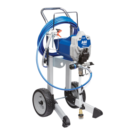
ti22086a
Pro Plus A60
Model: 16W515
Series A
Model: 17C246
Series A
Advertisement
Table of Contents
Troubleshooting

Related Manuals for Graco magnum pro plus a20


Summary of Contents for Graco magnum pro plus a20
- Page 1 Repair Magnum Plus A20, Pro Plus A20, Pro Plus A30, 332697C Pro Plus A45, and Pro Plus A60 Airless Sprayer - For portable spray applications of architectural paints and coatings - Models 16W108, 16E664, 16E665, 16W515, 17C243, 17C244, 17C245, 17C246 IMPORTANT SAFETY INSTRUCTIONS Read all warnings and instructions in this manual.
-
Page 2: Table Of Contents
General Repair Information ....14 Graco Standard Warranty ....60 Basic Troubleshooting . -
Page 3: Specifications
Specifications Specifications This equipment is not intended for use with flammable or combustible materials used in places such as cabinet shops or other “factory”, or fixed locations. If you intend to use this equipment in this type of application, you must comply with NFPA 33 and OSHA requirements for the use of flammable and combustible materials. -
Page 4: Warnings
Warnings Warnings The following warnings are for the setup, use, grounding, maintenance, and repair of this equipment. The exclama- tion point symbol alerts you to a general warning and the hazard symbols refer to procedure-specific risks. When these symbols appear in the body of this manual or on warning labels, refer back to these Warnings. Product-specific hazard symbols and warnings not covered in this section may appear throughout the body of this manual where applicable. - Page 5 • Check hoses and parts for signs of damage. Replace any damaged hoses or parts. • This system is capable of producing 3000 psi. Use Graco replacement parts or accessories that are rated a minimum of 3000 psi. • Always engage the trigger lock when not spraying. Verify the trigger lock is functioning properly.
- Page 6 Warnings WARNING WARNING WARNING WARNING EQUIPMENT MISUSE HAZARD Misuse can cause death or serious injury. • Do not operate the unit when fatigued or under the influence of drugs or alcohol. • Do not exceed the maximum working pressure or temperature rating of the lowest rated system component.
- Page 7 Warnings WARNING WARNING WARNING WARNING TOXIC FLUID OR FUMES HAZARD Toxic fluids or fumes can cause serious injury or death if splashed in the eyes or on skin, inhaled, or swallowed. • Read MSDSs to know the specific hazards of the fluids you are using. •...
-
Page 8: Component Identification A20 And A30
Component Identification A20 and A30 Component Identification A20 and A30 Airless spray gun Dispenses fluid. Power switch Turns sprayer ON and OFF. Pressure control knob Increases (clockwise) and decreases (counter-clockwise) fluid pressure in pump, hose, and spray gun. Setting Indicator To select function, align symbol on pressure control knob with setting indicator, page 13. - Page 9 Component Identification A20 and A30 Component Identification A20 and A30 (A20 shown) ti22057a 332697C...
-
Page 10: Component Identification A45 And A60
Component Identification A45 and A60 Component Identification A45 and A60 Airless spray gun Dispenses fluid. Power switch Turns sprayer ON and OFF. Pressure control knob Increases (clockwise) and decreases (counter-clockwise) fluid pressure in pump, hose, and spray gun. Setting Indicator To select function, align symbol on pressure control knob with setting indicator, page 13. - Page 11 Component Identification A45 and A60 Component Identification A45 and A60 (A60 shown) ti9346a ti22077a ti9670a ti22086a ti9669a ti22177a ti22176a 332697C...
-
Page 12: Grounding And Electrical Requirements
Grounding and Electrical Requirements Grounding and Electrical Requirements Fluid supply container: follow local code. Solvent pails used when flushing: follow local code. Use only conductive metal pails, placed on a grounded Sprayer must be grounded. Grounding reduces the risk surface such as concrete. Do not place the pail on a of static and electric shock by providing an escape wire nonconductive surface, such as paper or cardboard, for electrical current due to static build up or in the event... -
Page 13: Operation
Operation Operation See Operation manual for basic information on sprayer 2. Move Prime/Spray valve to PRIME to relieve pres- setup, flushing, and storage. sure. Trigger Lock Always engage the trigger lock when you stop spraying to prevent the gun from being triggered accidentally by ti9346a ti13961a hand or if dropped or bumped. -
Page 14: General Repair Information
General Repair Information General Repair Information Flammable materials spilled on hot, bare, motor could To reduce risk of serious injury, including electric shock: cause fire or explosion. To reduce risk of burns, fire or • Do not touch moving or electric parts with fingers or explosion, do not operate sprayer with cover tools while testing repair. -
Page 15: Basic Troubleshooting
Basic Troubleshooting Basic Troubleshooting Check everything in this Basic Troubleshooting table before you bring the sprayer to a Graco/M authorized AGNUM service center. Problem Cause Solution Power switch is on and sprayer is Pressure is set at zero pressure. Turn pressure control knob clockwise plugged in, but motor does not run, to increase pressure setting. - Page 16 A60: AutoPrime may need replace- ment. Turn power switch ON and lis- ten for “tap” in pump. If you do not hear “tap”, AutoPrime is damaged. Take sprayer to Graco/M AGNUM authorized service center. Inlet valve check ball or seat is dirty Remove inlet fitting.
- Page 17 Tighten suction tube connection. Inspect for cracks or vacuum leaks. If cracked or damaged, replace suction tube. Prime/Spray Valve is worn or Take sprayer to Graco/M AGNUM obstructed with debris. authorized service center. Pump check ball is stuck. Read Pump does not prime section in Basic Troubleshooting, page 15.
- Page 18 Basic Troubleshooting Problem Cause Solution Pressure is set at maximum but can- Reversible spray tip is in UNCLOG Rotate arrow-shaped handle on not achieve a good spray pattern. position. spray tip so it points forward in SPRAY position, see Operation manual.
- Page 19 Basic Troubleshooting Problem Cause Solution Fan pattern varies dramatically while Pressure control switch is worn and Take sprayer to Graco/M AGNUM spraying. causing excessive pressure varia- authorized service center. tion. Sprayer does not turn on promptly when resuming spraying. Cannot trigger spray gun.
-
Page 20: Advanced Troubleshooting
Advanced Troubleshooting Advanced Troubleshooting See Basic Troubleshooting first, page 15 for problems that are more easily remedied. Motor Does Not Operate Specific Problem Cause Solution Basic mechanical problems. Paint is frozen or hardened in See Basic Troubleshooting, page 15. pump. Gears are damaged. - Page 21 Advanced Troubleshooting Specific Problem Cause Solution Basic electrical problems. Motor overheated. Allow motor to cool for 45 minutes. Retry. Electrical outlet is damaged. Reset building circuit breaker or replace fuse. Try another outlet. Check electric supply with volt meter. Meter must read 220/240 VAC.
- Page 22 Advanced Troubleshooting Specific Problem Cause Solution Sprayer wiring problems. Sprayer power cord damaged. 1. Unplug sprayer power cord. 2. Disconnect brown and blue power cord wires NOTE: Remove enclosure at EMI filter. mounting screws and pull 3. Plug in power cord. enclosure away from drive housing.
-
Page 23: Circuit Breaker Is Tripping
Advanced Troubleshooting Circuit Breaker is Tripping Specific Problem Cause Solution Building circuit breaker opens Sprayer electrical wiring is Repair or replace any damaged wiring or as soon as sprayer is turned pinched or insulation is terminals. Securely reconnect wires. damaged. Wires between pressure control switch and control board are pinched. -
Page 24: Erratic Motor Operation
Advanced Troubleshooting Erratic Motor Operation Specific Problem Cause Solution Sprayer quits after running for Building circuit is overloaded. Remove other loads from building circuit or find 5 to 10 minutes. another circuit that has less load. See Grounding and Electrical Requirements, page 12. Electrical outlet supplying Try another outlet. -
Page 25: Low Or Fluctuating Output
Advanced Troubleshooting Low or Fluctuating Output Specific Problem Cause Solution See Basic Troubleshooting, Pump cycles, but output is low or surging. page 15. Worn or obstructed inlet and Check for worn pump valves as follows: outlet valves. Prime sprayer with paint. Turn the Prime/Spray valve to SPRAY position. -
Page 26: Excessive Pressure Build Up
Advanced Troubleshooting Specific Problem Cause Solution Motor runs and pump cycles, but Intake valve or outlet valve is not Remove and clean inlet valves and outlet valves. pressure does not build up. seating properly. Replace if necessary. See List of Kits, page 30. Pump packings are worn or Check for leaking around pump. -
Page 27: Motor Diagnostics
Motor Diagnostics Motor Diagnostics A20, A30, and A45 Motor Diagnostics reveal a damaged motor or if motor Check for electrical continuity in motor armature, brushes are shorter than 1/4 in. (6.4 mm) replace the windings and brush as follows: motor using Motor Kit. See List of Kits, page 30. If Motor Diagnostics reveal a damaged motor or if motor brushes are shorter than 1/4 in. -
Page 28: Pressure Control Switch Diagnostics
Pressure Control Switch Diagnostics Pressure Control Switch Pump Diagnostics Diagnostics NOTICE When repairing or cleaning the pump, never submerge 1. Unplug power cord and Relieve Pressure. See pump in water or allow fluid to enter pressure control. Pressure Relief Procedure, page 13. 2. -
Page 29: Control Board Diagnostics
Control Board Diagnostics Control Board Diagnostics A20, A30, and A45 NOTE: Check for motor problems before replacing con- NOTE: Check for motor problems before replacing con- trol board. A damaged motor may burn out a good con- trol board. A damaged motor may burn out a good con- trol board. -
Page 30: List Of Kits
List of Kits List of Kits Kit Number Models Kit Description 16G223 A20, A30, and A45 Control Board Kit 16W944 Control Board Kit 122893 Fuse 16G224 16E664 series A and16E665 series A Enclosure Kit 16X022 16E664 series B and16E665 series B Enclosure Kit 16X021 17C244 series A and 17C245 series A... - Page 31 List of Kits Kit Number Models Kit Description 16W860 Pump (Complete) 16G227 A30 and A45 Pump (Complete) 16W941 Pump (Complete) 256212 Lacquer Conversion Kit 332697C...
- Page 32 Notes Notes 332697C...
-
Page 33: Parts
Parts Parts A20 Pump Models 16W108, 17C243 ti22185b 332697C... -
Page 34: Parts List
Parts Parts List A20 Models 16W108, 17C243 Ref. Part Description Qty. Ref. Part Description Qty. 16W860 KIT, repair, pump, complete 115489 CLAMP, drain tube (includes 48, 49, 50, and 53) 116295 CLAMP, tube 123849 SPRING, compression 195084 TUBE, drain 124249 BALL, ceramic, si-n 112689 SCREW, button HD 16E844 KIT, repair, inlet valve 195400 CLIP, spring... - Page 35 Parts A20 Frame Models 16W108, 17C243 ti22518a 332697C...
- Page 36 Parts Parts List A20 Models 16W108, 17C243 Ref. Part Description Qty. Ref. Part Description Qty. HOSE, cpld, 1/4 in. x 25 ft. 16W317 FILTER, EMI bracket assy (includes 71, 13) 245449 Model 16W108 115492 SCREW, mach, slot hex wash hd 247339 Model 17C243 16W858 KIT, repair, enclosure, A20 34▲...
- Page 37 Parts A30 Pump Models 16E664 (Series A and B), 17C244 (Series A) ti17725c 332697C...
- Page 38 Parts Parts List A30 Models 16E664 (Series A and B), 17C244 (Series A) Ref. Part Description Qty. Ref. Part Description Qty. 197607 TUBE, suction set 16G227 KIT, repair, pump, complete (includes 1a, 1b, 1c, 1d, 1e, 1f, 72) 16F635 LABEL, control, Magnum 235014 KIT, replacement, valve, drain 195400 CLIP, spring 24E578 BASE, valve...
- Page 39 Parts A30 Frame (Series A) Model 16E664 (Series A) ti18695b 332697C...
- Page 40 Parts Parts List A30 Model 16E664 (Series A) Ref. Part Description Qty. Ref. Part Description Qty. 256992 HANDLE, painted 112689 SCREW 116139 GRIP, handle 16D684 FRAME 122233 BOLT, carriage 115498 SCREW, mach, slot hex wash hd (not shown) 102040 NUT, lock, hex 16G224 KIT, repair, enclosure, A30 and A45 16F567 BRACKET, control board/EMI filter series A (includes 11, 17, 39)
- Page 41 Parts A30 Frame Models 16E664 (Series B), 17C244 (Series A) ti22460a 332697C...
- Page 42 Parts Parts List A30 Models 16E664 (Series B), 17C244 (Series A) Ref. Part Description Qty. Ref. Part Description Qty. 16W431 KIT, accessory, gun, SG3 112689 SCREW 47▲ 179960 SIGN, warning (not shown) 16D684 FRAME 256992 HANDLE, painted 115498 SCREW, mach, slot hex wash hd (not shown) 116139 GRIP, handle 16X022 KIT, repair, enclosure, A30 and A45...
- Page 43 Parts A45 Pump Models 16E665 (Series A and B), 17C245 (Series A) ti17724c 332697C...
- Page 44 Parts Parts List A45 Models 16E665 (Series A and B), 17C245 (Series A) Ref. Part Description Qty. Ref. Part Description Qty. 16D951 TUBE, suction 16G227 KIT, repair, pump, complete (includes 1a, 1b, 1c, 1d, 1e, 1f, 72) 16F635 LABEL, control, magnum 235014 KIT, replacement, valve, drain 195400 CLIP, spring 24E578 BASE, valve...
- Page 45 Parts A45 Frame Model 16E665 (Series A) ti18694a 332697C...
- Page 46 Parts Parts List A45 Model 16E665 (Series A) Ref. Part Description Qty. Ref. Part Description Qty. 120788 SCREW, carriage 112689 SCREW, button HD 256993 HANDLE, painted 16D685 FRAME 115480 KNOB, t-handle 16G224 KIT, repair, enclosure, A30 and A45, Series A (includes 11, 17, 39) 257326 RACK, hose, painted 115477...
- Page 47 Parts A45 Frame Models 16E665 (Series B), 17C245 (Series A) ti22517a 332697C...
- Page 48 Parts Parts List A45 Models 16E665 (Series B), 17C245 (Series A) Ref. Part Description Qty. Ref. Part Description Qty. 112612 CAP, hub 112689 SCREW, button HD 260212 SCREW, hex washer hd, thd form 16D685 FRAME 120788 SCREW, carriage 16X022 KIT, repair, enclosure, A30 and A45, Series B (includes 11, 17, 39) 256993 HANDLE, painted 115477 SCREW, mach, torx pan hd...
- Page 49 Parts A60 Pump Models 16W515, 17C246 ti22196b 332697C...
- Page 50 Parts Parts List A60 Models 16W515, 17C246 Ref. Part Description Qty. Ref. Part Description Qty. 118444 SCREW, mach, slot hex wash hd 16D576 LABEL,made in USA 260212 SCREW, hex washer hd, thd form 245673 STRAINER, 3/4-16 unf LABEL, A60, front 15E813 NUT, jam 16W632 Model 16W515...
- Page 51 Parts A60 Frame Models 16W515, 17C246 ti22459a 332697C...
- Page 52 Parts Parts List A60 Models 16W515, 17C246 Ref. Part Description Qty. Ref. Part Description Qty. 112612 CAP, hub 16W947 KIT, repair, right leg (includes 43) 120689 NUT, hex, acorn, 5/16-18, nickel 16W946 KIT, repair, left leg (includes 43) 115094 WHEEL, 10 in. 16W362 AXLE, cart 260212 SCREW, hex washer, hd, thd form 16W200 SHELF, motor...
-
Page 53: Wiring Diagram
Wiring Diagram Wiring Diagram A30 (Series A) and A45 (Series A) Models 16E664 (Series A) and 16E665 (Series A) Power Cord Power Cord Green Wire Brown Wire ON/OFF Switch Power Cord Blue Wire Black Motor Lead Black Motor Lead ti16291a 332697C... - Page 54 Wiring Diagram A20, A30 and A45 Models 16W108 (Series A), 16E664 (Series B), 16E665 (Series B) Models 17C243 (Series A), 17C244 (Series A) Power Cord Power Cord Brown Wire Blue Wire Power Cord Green Wire ON/OFF Switch Pressure Control Ref. EMI Filter Ferrite Harness Black Motor Lead with White Heat Shrink...
- Page 55 Wiring Diagram Models 16W515, 17C246 Power Switch Brown Wire Motor AutoPrime Blue Wire Brown Wire Pressure Control Green/Yellow Wire ti22243b 332697C...
-
Page 56: Technical Data
Technical Data Technical Data Working pressure range 0-207 BAR, 0-21 Mpa (0-3000 psi) Electric Motor 4.5A (open frame, universal) Operating horsepower Maximum delivery (with tip) .91 lpm (.24 gpm) 1.02 lpm (.27 gpm) Paint hose 6.4mm X 7.5 m (1/4 in. x 25 ft) Maximum tip hole size 0.015 in. - Page 57 Technical Data Working pressure range 0-207 BAR, 0-21 Mpa (0-3000 psi) Electric Motor 4.5A 6.5A (open frame, universal) (open frame, permanent magnet DC) Operating horsepower Maximum delivery (with tip) 1.17 lpm (.31 gpm) 1.44 lpm (.38 gpm) Paint hose 6.4mm X 15 m (1/4 in. x 50 ft) Maximum tip hole size 0.017 in.
- Page 58 Notes Notes 332697C...
- Page 59 Notes Notes 332697C...
-
Page 60: Graco Standard Warranty
With the exception of any special, extended, or limited warranty published by Graco, Graco will, for a period of twelve months from the date of sale, repair or replace any part of the equipment determined by Graco to be defective.