Advertisement
Table of Contents
Advertisement
Table of Contents

Related Manuals for Electrolux EGG7222SX


Summary of Contents for Electrolux EGG7222SX
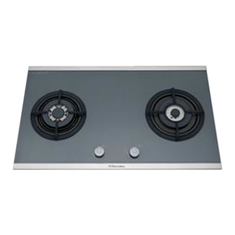
- Page 1 SERVICE MANUAL...
-
Page 2: Table Of Contents
C O N T E N T S 1. GENERAL NOTES 2. HOW DOES GAS BURNER OPERATE 3. COMPONENTS SPECIFICATION 3.1 City gas accessories 4. TOOLS 5. REPAIR PROCESS 5.1 Remove the dirty oil from nozzle 5.2 Remove the gas valve 6. -
Page 3: General Notes
1. GENERAL NOTES 1.1 WARNING: For models which connect to mains electrical power, before exposing any of the internal electrical wiring the appliance must be disconnected from electrical power by unplugging the service cord from the electrical outlet. For models which connect to battery power, before exposing any of the internal electrical wiring the appliance must be remove the battery also. -
Page 4: How Does Gas Burner Operate
2. HOW DOES GAS BURNER OPERATE 1. Gas tank 2. Low pressure regulator (Safety warning: Do not use high pressure regulator) 3. Flexible rubber hose or copper tube 4. Elbow coupling gas with fibre washer (Warning: Do not use regular rubber washer) 5. -
Page 5: Components Specification
Gas from the tank (1) is released from the low pressure regulator (2) into the hose or tube (3), travelling pass the elbow coupling to the valve (4). To ignite the burner, press down and turn the safety valve (5) counter- clockwise simultaneously. -
Page 6: City Gas Accessories
3.1 Citi Gas Accessories - Shutter Aeration (Semi Papid) (TH-0003/ZA) - Shutter Altration ( Triple Crown) (TH-0003/ZB) - Injector 2.1 (Semi Rapid) (TH-0003/CD) - Injector 4.0 (Triple Crown) (TH-0003/ZA) - Injector 3.5 (Defendi Outer) (TH-0003/CL) - Shutter Aeration (Defendi Outer) (TH-0003/ZC) - Injector 1.2 (Defendi Outer) (TH-0003/CM) -
Page 7: Tools
- Screw, M4x0.7x10 IP - Screw, M4x0.7x18 H - Screw, M3x12T + B stainless - Screw, #6/32 x 9 PPZF - Screw, #8 x ½ T+ Z 4. TOOLS Socket Spanner 7 - Nut spinner No. 7 - Philip / Flat screw driver - Spanner No. - Page 8 4. Remove burner mount retaining screws, 2 screws per burner and 4 on the wok burner (2.5mm Torque Screwdriver required). 5. For models with a separate button ignition system, remove the switch button and ignition pack retaining nut. Alternatively, lift the hob sufficiently to access and release the ignition leads and battery supply cable from the ignition pack.
-
Page 9: Wiring Diagram
• Switch harness assembly and low voltage wiring. • Ignition spark plug and lead assemblies. These are fastened to the burner bases by retaining clips, located on the underside of the burner base. • Ignition pack. For models without a separate ignition switch this is clipped to the base or attached with double sided adhesive. -
Page 10: Conversion Details
7. CONVERSION DETAILS The appliance is convertible between Natural Gas & LP. Procedure 1. Turn off gas supply to appliance. 2. Disconnect appliance from electrical power. 3. Remove the trivets and the burner caps & distributors. 4. Remove the existing injectors and replace with the injectors shown in the table below. 5. -
Page 11: Spare Parts
30.0 mbar 8.0 mbar 20.0 mbar Injector Rating Injector Rating Injector Rating BURBERS size (KW) size (KW) size (KW) Triple crown 0.98 4.00 Semi-rapid 0.71 2.10 0.96 Defendi 1.05 x 1.4 x 0.37 X 1.2 0.63 9. SPARE PARTS EGG7222SX... - Page 12 MODEL - ELECTROLUX EGG 7222SX 76CM POWER PARTS LIST REF # : H/A/372 CODE NO PART NAME UNIT (PCS) TH-0008/MB C/IRON HOB(R)BL-POWER-TRIPLE C TH-0008/MA C/IRON G/HOB(R)BH-POWER-DEFEND TH-0009/DE S/S TRAY-BIG-TRIPLE CROWN TH-0011/AE SILICONE RUBBER TUBING-D:165MM TH-0009/DD S/S TRAY HOB-DEFENDI TH-0006/ZH B/CAP TRIPLE CROWN INNER MATT...
- Page 13 GENERATOR COVER (ALSTAR) TH-0005/UE BATTERY BOX COVER (ALSTAR) TH-0014/AB FOAM W/ONE SIDE D/SIZE TAPE EH-0161/AB BURBLE SHEET:880 X 580 X 10MM H2-0202/CD GUARANTEE CARD: ELECTROLUX H2-0216/BS PE PLASTIC BAGS:9" X 14" TH-0012/DB 3M TAPE (760 X 20MM) TH-0019/AE HOB POLYFOAM-ELECTROLUX-NICKY TH-0019/BE...
- Page 14 EGT7223SX...
- Page 15 MODEL - ELECTROLUX EGT 7223X 76CM POWER PARTS LIST REF # : H/A/373 CODE NO PART NAME UNIT (PCS) TH-0008/MB C/IRON HOB(R)BL-POWER-TRIPLE C TH-0008/MA C/IRON G/HOB(R)BH-POWER-DEFEND TH-0009/DE S/S TRAY-BIG-TRIPLE CROWN TH-0011/AE SILICONE RUBBER TUBING-D:165MM TH-0009/DD S/S TRAY HOB-DEFENDI TH-0006/ZH B/CAP TRIPLE CROWN INNER MATT...
- Page 16 TH-0023/BD REGULATOR STICKER TH-0023/BQ GAS LEAKAGE WARNING SLIP-ELUX TH-0026/AD SHRINK TUBE-6MM X 100MM TH-0027/FM PACKING STICKER-EGG7223X(LPG) TH-0027/GM RATING LABEL-EGT7223X(LPG) TH-0028/AA GAS TYPE LABEL(LPG) ZANUSSI/ XH-0001/GA BATTERY STICKER (XINBAO HOB) EH-0161/AB BURBLE SHEET:880 X 580 X 10MM H2-0202/CD GUARANTEE CARD: ELECTROLUX...
- Page 17 EHT 7123X...
- Page 18 MODEL - ELECTROLUX EHT 71223X 76SS POWER PARTS LIST UNIT CODE NO PART NAME (PCS) TH-0008/NB CAST IRON WOK ADAPTOR-01270012 TH-0008/NA CAST IRON STAND(SQ)-0127001237 TH-0005/UC GENERATOR COVER (ALSTAR) TH-0005/UE BATTERY BOX COVER (ALSTAR) TH-0005/ZY SPARKER CLIP (DEFENDI) TH-0006/ZH B/CAP TRIPLE CROWN INNER MATT...
- Page 19 DEFENDI INLET NUT TH-0004/LA BICONIC RING TH-0012/AA GAS HOB BASE LINING EH-0161/AB BURBLE SHEET:880 X 580 X 10MM H2-0202/CD GUARANTEE CARD: ELECTROLUX XH-0001/GA BATTERY STICKER (XINBAO HOB) TH-0019/AE HOB POLYFOAM-ELECTROLUX-NICKY TH-0019/DA TRIPLE CROWN TOP PACK FOAM TH-0019/DB DEFENDI TOP PACK FOAM...
-
Page 20: Trouble Shooting
10. TROUBLE SHOOTING Fault Possible cause Remedy Burner will not light even -Gas supply valve turned off -Turn on gas supply to appliance though the spark plug is -Control knob not on -Turn knob on working -Wrong knob turned -Ensure the knob you are turning correspond to the burner you want to light -Port blockage in ignition...