Table of Contents
Advertisement
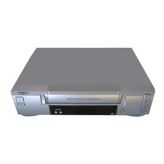
SERVICE MANUAL
Video cassette recorder
(VHR-M292E)
KR2LN/EV4,SP2,PR,E2,EV3,IR2
KR4HN/EV,SP,PR,E,IR,E2
FILE NO.
VHR-M262EV
(Product Code : 143 182 34)
(Europe)
VHR-M272SP
(Product Code : 143 182 36, 40)
(Spain), (Portugal)
VHR-M292E
(Product Code : 143 182 31)
(U.K.)
VHR-M292EV
(Product Code : 143 182 33)
(Europe)
VHR-M292IR
(Product Code : 143 182 38)
(Ireland)
PAL
VHR-H772EV
(Product Code : 143 182 32)
(Europe)
VHR-H772SP
(Product Code : 143 182 35, 39)
(Spain), (Portugal)
VHR-H792E
(Product Code : 143 182 29)
(U.K.)
VHR-H792IR
(Product Code : 143 182 37)
(Ireland)
VHR-H802E
(Product Code : 143 182 30)
(U.K.)
REFERENCE No.SM5310389
Advertisement
Table of Contents
Troubleshooting

Related Manuals for Sanyo VHR-M262EV


Summary of Contents for Sanyo VHR-M262EV
- Page 1 FILE NO. SERVICE MANUAL VHR-M262EV Video cassette recorder (Product Code : 143 182 34) (Europe) VHR-M272SP (Product Code : 143 182 36, 40) (Spain), (Portugal) VHR-M292E (Product Code : 143 182 31) (U.K.) VHR-M292EV (Product Code : 143 182 33)
-
Page 2: Table Of Contents
TABLE OF CONTENTS SECTION 1 BLOCK DIAGRAMS .....3-21 1. Power Block Diagram ....3-21 SUMMARY 2. - Page 3 SECTION 4 MECHANISM CONTENTS DECK MECHANISM PARTS DECK MECHANISM ADJUSTMENT LOCATIONS • Tools and Fixtures for Service.....4-12 1. Mechanism Alignment Position Check..4-13 • Top View...........4-1 2. Preparation for Adjustment......4-14 • Bottom View ..........4-1 3. Checking Torque ........4-14 DECK MECHANISM 4. Guide Roller Height Adjustment....4-15 4-1.
-
Page 4: Key To Abbreviations
SECTION1 SUMMARY KEY TO ABBREVIATIONS :Alternating Current :Low Pass Filter :Automatic Color Control :Maximum ACSS :Automatic Channel Setting System :Modulator :Adjust MECHA.CTL :Mechanism Control :Audio Erase :Microphone :Automatic Frequency Control :Minimum :Automatic Fine Tuning :Mixer, Mixing :Automatic Gain Control M.M. :Monostable, Multivibrator A.H.SW :Audio Head Switch... -
Page 5: Important Safety Precautions
IMPORTANT SAFETY PRECAUTIONS Prior to shipment from the factory, the products are strictly inspected to conform with the recognized product safety and electrical codes of the countries in which they are to be sold. However, in order to maintain such com- pliance, it is equally important to implement the following precautions when a set is being serviced. -
Page 6: Safety Check After Servicing
SAFETY CHECK AFTER SERVICING Examine the area surrounding the repaired location for damage or deterioration. Observe that screws, parts and wires have been returned to original positions. Afterwards, perform the following tests and confirm the specified values in order to verify compliance with safety standards. •... -
Page 7: Proposal For Applying Short Protection
PROPOSAL FOR APPLYING SHORT PROTECTION • The Contents of Examination As all the IC that is applied to VCR is controlled by IIC, mutual communication, if Vcc of IC is short or open with detecting ‘Acknowledge’ data of the specific IC according to each power(5V, 5VT) µ-COM gets unable to detect ‘ACK’... -
Page 8: Service Notice On Replacing Eeprom
SERVICE NOTICE ON REPLACING EEPROM In case that defective EEPROM of PAL models is replaced, to operate these sets from the initial state MP KEY must be repaired as well before delivering to the customer. If MP KEY isn’t repaired the setting of RF OUT channel or LANGUAGE might be different from that for cus- tormer’s country. -
Page 9: Ic Setting
- Eeprom EDIT screen automatically appears if replacing OPT1 00000000 Eeprom. OPT2 00000000 OPT3 00000000 For SANYO model, change a remocon key by using fol- OPT4 00000000 lowing JIG key. OPT5 00000000 SANYO MODEL : FRONT UP + FRONT FF OPT6... -
Page 10: Specifications
Timer : 24 hours display type Video Television system : CCIR standard (625 lines, 50 fields) PAL colour signal Recording format : PAL B/G(VHR-M262EV/M292EV/H772EV/ VHR-M272SP(SPAIN)/H772SP(SPAIN)/ M272SP(PORTUGAL)/H772SP(PORTUGAL) PAL I(VHR-M292E/H792E/H802E) PAL I/I(VHR-M292IR/H792IR) Input level : VIDEO IN (SCART, RCA type) 1.0 Vp-p, 75 ohm, unbalanced... -
Page 12: Cabinet & Main Chassis
SECTION 2 CABINET & MAIN CHASSIS SERVICE METHOD Electrical Part (1) Re-assembly Flow for service like Fig. 2-1 Timer C.B.A Main C.B.A Housing & Deck Assembly (2) To check and replace Electrical parts Re-assemble the unit according to No.1) Re-assembly Flow. Place the unit like Fig. -
Page 13: Exploded Views
EXPLODED VIEWS 1. Cabinet and Main Frame Section NOTE) Refer to “SECTION 5 REPLACEMENT PARTS LIST” in order to look for the part number of each part. _ OPTIONAL PARTS... -
Page 14: Packing Accessory Section
2.Packing Accessory Section NOTE) Refer to “SECTION REPLACEMENT PARTS LIST NOTE) in order to look for the part number of each part. OPTIONAL PARTS CABLE SET ASS'Y (Optional parts) INSTRUCTION MANUAL PACKING (LF) BAG. SOFT SHEET PACKING (RF) BOX CARTON REMOCON... -
Page 16: Electrical Adjustment Points Arrangement
SECTION 3 ELECTRICAL ELECTRICAL ADJUSTMENT POINTS ARRANGEMENT : Measurement point : Adjustment point SCART JACK Speak-ez SW/IC Hi-Fi SECAM AVCP W501 H.S/W W502 SYSTEM Micom EEPROM NICAM CLK IC E2PROM DISPLAY(DOT,CLK) (COMPONENT SIDE) -
Page 17: Electrical Adjustment Procedures
ELECTRICAL ADJUSTMENT PROCEDURES 1. Servo Adjustment 1) PG Adjustment • Test Equipment a) OSCILLOSCOPE b) PAL TEST TAPE (VHS SP) c) JIG REMOCON (AUTO PG SETTING) • Adjustment And Specification MODE MEASUREMENT POINT ADJUSTMENT POINT SPECIFICATION V.Out PLAY 6.5 ± 0.5H H/SW(W501, W502) •... - Page 18 ELECTRICAL ADJUSTMENT PROCEDURES • WAVEFORM H/SW 6.5H(416us) Composite VIDEO • Attension and Reference a) The PG checking must do when RF Level is Maximum and SERVO system is Locking (MTR MODE) b) V.H/SW Level is 2Vpp.
-
Page 19: Electrical Troubleshooting Guide
ELECTRICAL TROUBLESHOOTING GUIDE 1. Power Circuit(SMPS) (1) No 5.3VA. No 5.3VA. Replace the F101 Is the F101 normal? (Use the same Fuse). Is the BD101 normal? Replace the BD101. Is the R101 normal? Replace the R101. Does the oscillation waveform appear at Is Vcc(about 13~15V) permittable at the the IC101 Pin 7? IC101 Pin 3? - Page 20 7. Power Circuit(SMPS) (2) No 12VA.(Capstan) No 12VA. Does 5.3VA work normally? Check whether 5.3VA is out of order. Is the D109 normal? Replace the D109. Check 12VA Line of the Main PCB short. (3) No 12VA (CANAL, Buffer) No 12VA. Is Vcc(about 13VA) put into the Q155(E)? Replace the Peripheral Circuitry of D160.
- Page 21 7. Power Circuit(SMPS) (4) No 5VT(5V) No 5VT.(5V) Is 5.3VA put into the Q152(Q151) collector? Is the Q163(Q162) Base “H”? Check the µ-com Control. Is about 4.7V put into the Check the Q163(Q162) Q152(Q151) Base? whether it works normally. Check or Replace the Q152(Q151).
-
Page 22: Servo Circuit
2. Servo Circuit Unstable Video in PB Mode. Does the on screen noise level change periodically? Do CTL pulses appear at IC501 pin 8? Does the CFG divide Is the height of the CTL waveform appear at IC501 Head adjusted correctly? pin 9? Do the CTL pulses move Adjust the CTL Head. - Page 23 Drum Motor stopped. Does 12V appear at PMC01 Pin 8? Does 2.8V appear at PMD01 Pin 12? Check Power. Does Drum PWM appear at IC501 Pin Check Connector and Drum Motor Ass’y. 107? Check the Components and foil Pattern between IC501 Pin 26 and PMC01 Do DFG Pulses appear at PMD01 Pin 3? Pin 12 for shorts.
- Page 24 Capstan Motor Stopped. Does 13VA appear at PMC01 Pin 2? Does 2.8V appear at PMC01 Pin 9? Check Power. Check Connector and Capstan Does PWM wave appear at IC501 Motor Ass’y. Pin 108? Check the Components and foil Patterns Does the CFG signal appear at PMC01 Connected between IC501 Pin 108 and Pin 1? PMC01 Pin 9 for shorts.
-
Page 25: System & Front Panel Circuit
3. System & Front Panel Circuit Auto stop. Does SW30 waveform appear at IC501 Pin 105? Do Take-up reel pulses Check the Drum Motor appear at IC501 Pin 49? Signal. Do Take-up reel pulses Change IC501. appear at the base of Q514? Does 5.3V appear at RS501. - Page 26 Cassette tape loading is unstable. Is REG 14VA applied to PMC01 Pin 8? Is High signal applied to IC501 Pin 30 Check the power. when inserting the CST? Is 5.4VA applied to R544? Does Low signal occur form PMC01 Check the CST SW and Check the power.
-
Page 27: Y/C Circuit
4. Y/C CIRCUIT (1) No Video in EE Mode, No Video in EE Mode Check the Video Input Does the Video signal Jack. appear at the IC301 Pin 48? (Line In Jack) Is 5V applied to the IC301 Check the 5.2VT, 5.4VA Pins 18, 24, 42, 55, 72, 91? Line. - Page 28 3. Y/C CIRCUIT (2) When the Y(Luminance) signal doesn’t appear on the screen in PB Mode, Check the line of the Is 5.2VT, 5.4VA applied to the 5.2VT/5.4VA Line. IC301 Pins 24, 42, 55, 72, 91? (Power Circuit) Is the I C Bus siganl applied Refer to ‘SYSTEM I C BUS...
- Page 29 3. Y/C CIRCUIT (3) When the C(Color) signal doesn’t appear on the screen in PB Mode, Is 5.2VT/5.4VA applied to the Check the line of the 5.2VT/ 5.4VA Line. (Power Circuit) IC301 Pins 24, 42, 55, 72, 91. Is the Color Rotary signal Check the Color Rotary applied to the IC301 Circuit.
- Page 30 3. Y/C CIRCUIT (4) When the Video signal doesn’t appear on the screen in REC Mode, Is the EE signal normal? Check EE Mode. Is 5.2VT/5.4VA applied to the Check the line of the 5.2VT/ IC301 Pins 24,42,55,72,91? 5.4VA Line.(Power Circuit) Does PB Mdoe operate Check PB Mode.
-
Page 31: Tuner/If Circuit
5. Tuner/IF circuit (1) No picture on the TV screen No picture on the TV screen Does the Video signal at Is +30VT applied to Check 33VT line. the TU701 Pin24? TU701 Pin 16? Is +5VT applied to Check 5VT line. TU701 Pin 13? Does the Clock signal Check the liC Clock... - Page 32 (2) No sound (Mono Model) No sound Check the Vcc of IC301 Pin 18. Check 5VT power. Check the Tuner Audio signal Chekc the signal flow from TU701 at IC301 Pin 13. Pin21 to IC301 Pin 13. Check the Audio signal at IC301 Pin 11. Replace IC301.
- Page 33 (3) No sound (Hi-Fi Model) No sound Check the Vcc of IC751 Pins 1, 19, 33. Check 5V power. Check the Tuner SiF signal at IC751 Pin 2. Check the Tuner Audio of TU701 Pin 21. Check the oscillator of IC751 Pins 5, 6. Replace X751.
-
Page 34: Hi-Fi Circuit
6. Hi-Fi Circuit (Hi-Fi Model) Hi-Fi Playback. Check the Vcc of No sound IC801.(Pins 34, 40) Check the Hi-Fi Selection Check power. Switch and the Tape quality. Is the RF Envelope at Is the Head switching signal Check IC501 Pin 23. IC801 Pin 44 over 2Vp-p? IC802 Pin 41 O.K? (Audio head switch 25) - Page 35 Hi-Fi REC. It is impossible to record and playback Hi-Fi Audio signal. Check Vcc of IC801. (Pins 34,40) Check IC801 Pin 42(Data),Pin 43(CLOCK). Check Power. Do Audio signals appear at IC801 Check ports of µ-COM. Pins 16, 17? Do FM Audio signals appear at IC801 Check Audio input signal of IC801 Pin 36? Pins 2, 3(TU.A.), 6, 7(Scart 1)
-
Page 36: Deck Mechanism Parts Locations
DECK MECHANISM PARTS LOCATIONS • Top View Pracedure Fig- Part Fixing Type Starting 1 Drum Assembly 3 Screw 2 Plate Top 2 Hook 3 Holder Assembly CST Chassis Hole 4 Opener Door Chassis Hole 5 Bracket Assembly 3 Hook L/D Motor 2,3,4 6 Gear Assembly Rack F/L 1 Hook, Chassis Hole A-2... -
Page 37: Deck Mechanism Disassembly
DECK MECHANISM DISASSEMBLY Stator (S2) (S2) (S3) Drum Motor (S3) Rotor Drum Sub Assembly (Fig. A-1-1) Drum FPC Carbon Brush (S1) (S1) (S1) Holder FPC Fig. A-1 (Fig. B-1) 1. Drum Assembly (Fig. A-1-1) 1) Unplug the Drum FPC Connector. 2) Remove three Screws(S1) on bottom side and separate the Drum assembly. -
Page 38: Plate Top
DECK MECHANISM DISASSEMBLY (Fig. A-2-1) Plate Top (B') (Fig. A-2-2) Holder Assembly CST (Fig. A-2-6) Arm Assembly F/L (C1) (Fig. A-2-7) Lever Assembly S/W (H8) Brackert Assembly L/D Motor Spring Lever S/W (Fig. A-2-4) (C') (E') Opener Door (Fig. A-2-3) (H6) Chassis Gear Assembly Rack F/L... - Page 39 DECK MECHANISM DISASSEMBLY 2. Plate Top (Fig. A-2-1) 2) Unhook three Hooks(H3,H4,H5) on bottom side of the Chassis, lift up the Bracket assembly L/M and disassem- 1) Pull the (B) portion of the Plate Top back in direction of ble the Bracket assembly L/D Motor. arrow and separate the right side of it.
-
Page 40: Arm Assembly Cleaner
DECK MECHANISM DISASSEMBLY Arm Assembly Cleaner (Fig. A-3-1) (S4) Base Assembly A/C Head *(Fig. A-3-3) Head F/E (Fig. A-3-2) Chassis Fig. A-3 9. Arm assembly Cleaner (Fig. A-3-1) 11. Base assembly A/C Head (Fig. A-3-3) 1) Breakaway the (A) portion as Fig. A-3-1 from the 1) Remove the Screw(S4) and lift the Base assembly A/C Embossing of the Chassis, turn the Arm assembly Head up. -
Page 41: Brake Assembly T
DECK MECHANISM DISASSEMBLY Arm Assembly Tension (Fig. A-4-3) (H11) Spring TB Brake Assembly T (Fig. A-4-1) Spring Tension Reel S Reel T (Fig. A-4-4) (Fig. A-4-4) Spring RS Brake Assembly RS (Fig. A-4-2) (H12) (H9) (H10) Base Tension Chassis Fig. A-4 12. -
Page 42: Base Assembly P4
DECK MECHANISM DISASSEMBLY Opener Lid (Fig. A-5-2) Assembly Pinch (Fig. A-5-3) Base Assembly P4 Lever T/up (H13) (Fig. A-5-1) (Fig. A-5-4) (H13) Arm T/up (Fig. A-5-5) Chassis Fig. A-5 16. Base assembly P4 (Fig. A-5-1) 19. Lever T/up (Fig. A-5-4)/ 1) Breakaway the (A) portion of the Base assembly P4 from Arm T/up (Fig. -
Page 43: Belt Capstan/Motor Capstan
DECK MECHANISM DISASSEMBLY Belt Capstan (Fig. A-6-1) Motor Capstan (Fig. A-6-2) Washer(W1) Clutch Assembly D35 (Fig. A-6-4) (L1) (L1) Brake Assembly Capstan (Fig. A-6-5) Lever F/R (Fig. A-6-3) (L2) Chassis (S5) Fig. A-6 20. Belt Capstan (Fig. A-6-1)/ 22. Clutch assembly D35 (Fig. A-6-4) Motor Capstan (Fig. -
Page 44: Gear Drive/Gear Cam
DECK MECHANISM DISASSEMBLY (H14) Gear Cam Hole(B) Gear Cam (Fig. A-7-2) Gear Drive Hole(A) Gear Sector Washer (W2) (Fig. A-7-3) Plate Slider Gear Drive (Fig. A-7-4) (Fig. A-7-1) Lever Tension (Fig. A-7-5) Lever spring (L3) (Fig. A-7-6) Gear Drive Hole(C) Base Loading (H15) (H16) -
Page 45: Gear Assembly P2
DECK MECHANISM DISASSEMBLY Gear assembly P2 Hole Gear assembly P3 Hole Gear Assembly P3 (Fig. A-8-2) Gear sector Hole(A) Lever spring Boss Gear Assembly P2 Plate slider Hole(B) (Fig. A-8-1) Chassis Base Assembly P3 (Fig. A-8-4) Base Assembly P2 (Fig. A-8-3) Fig. -
Page 46: Base Loading
DECK MECHANISM DISASSEMBLY (S7) Base Tension Base Loading (Fig. A-9-2) Arm Assembly Idler Jog (Fig. A-9-1) (Fig. A-9-3) Chassis Fig. A-9 31. Base Loading (Fig. A-9-1) 33. Arm assembly Idler Jog(Fig. A-9-3) 1) Remove the Screw(S7). 1) Make narrower the two parts, (A) and (B), as Fig. A-9-3. 2) Lift the Base Loading up. -
Page 47: Deck Mechanism Adjustment
DECK MECHANISM ADJUSTMENT • Tools and Fixfures for Service 1. Cassette Torque meter 2. Alignment tape 3. Torque gauge SRK-VHT-303(Not SVC part) Parts No NTSC: DTN-001 600g.Cm ATG Parts No: D00-D006 PAL:DTN-0002 Parts No:D00-D002 4. Torque gauge adaptor 5. Post height adjusting driver 6. -
Page 48: Mechanism Alignment Position Check
DECK MECHANISM ADJUSTMENT 1.Mechanism Alignment Position Check Purpose:To determine if the Mechanism is in the correct position, when a Tape is ejected. Test Conditions (Mechanism Test Equipment/ Fixture Check Point Condition) • Mechanism and Mode Switch Position • Blank tape •... -
Page 49: Preparation For Adjustment
DECK MECHANISM ADJUSTMENT 2. Preparation for Adjustment (To set the Cassette without Tape. Cover the Holes of the End Sensors at the both sides of Deck Mechanism to the Loading state the Bracket Side(L) and Bracket Assembly Door to pre- without inserting a Cassette Tape). -
Page 50: Guide Roller Height Adjustment
DECK MECHANISM ADJUSTMENT 4.Guide Roller Height Adjustment Purpose: To regulate the Height of the Tape so that the Bottom of the Tape runs along the Tape Guide Line on the Lower Drum. 4-1. Preliminary Adjustment Test Equipment/ Fixture Test Conditions (Mechanism Condition) Adjustment Point •... -
Page 51: Audio/Control (A/C) Head Adjustment
DECK MECHANISM ADJUSTMENT 5. Audio/Control (A/C) Head Adjustment Purpose: To insure that the Tape passes accurately over the Audio and Control Tracks in exact Alignment in both the Record and Playback Modes. 5-1. Preliminary Adjustment (Height and Tilt Adjustment) Perform the Preliminary Adjustment, when there is no Audio Output Signal with the Alignment Tape. Test Equipment/ Fixture Test Conditions (Mechanism Condition) Adjustment Point... -
Page 52: Precise Adjustment(Azimuth Adjustment)
DECK MECHANISM ADJUSTMENT 5-2. Confirm that the Tape passes smoothly slowly turn the Tilt Adjustment Screw(C) in the Counterclockwise direction. between the Take-up Guide and Pinch Roller(using a Mirror or the naked eye). After completing Step 5-1.(Preliminary Adjustment), NOTE: check that the Tape passes around the Take-up Guide and Pinch Roller without Folding or Curling at the Top or Check the RF Envelope after adjusting the A/C Head, if Bottom. -
Page 53: Adjustment After Replacing Drum Assembly (Video Heads)
DECK MECHANISM ADJUSTMENT 7. Adjustment after Replacing Drum Assembly (Video Heads) Purpose: To correct for shift in the Roller Guide and X value after replacing the Drum. Test Conditions Test Equipment/ Fixture Connection Point Adjustment Points (Mechanism Condition) • CH-1: PB RF Envelope •... -
Page 54: Maintenance/Inspection Procedure
MAINTENANCE/INSPECTION PROCEDURE 1 Check before starting repairs The following faults can be remedied by cleaning and oil- ing. Check the needed lubrication and the conditions of cleanliness in the unit. Check with the customer to find out how often the unit is used, and then determine that the unit is ready for inspec- tion and maintenance. -
Page 55: Required Maintenance
MAINTENANCE/INSPECTION PROCEDURE 4. Supplies Required for Inspection and 2. Required Maintenance Maintence The recording density of a VCR(VCP) is much higher than that of an audio tape recorder. VCR(VCP) components must (1) Grease : Kanto G-311G (Blue) or equivalent be very precise, at tolerances of 1/1000mm, to ensure com- (2) Isopropyl Alcohol or equivalent patiblity with other VCRs. -
Page 56: Greasing
MAINTENANCE/INSPECTION PROCEDURE (2) Periodic greasing 5-2) Greasing Grease specified locations every 5,000 hours. (1) Greasing guidelines Apply grease, with a cleaning patch. Do not use excess 1) Loading Path Inside & Top side 5) Lever Tension Groove grease. It may come into contact with the tape transport 2) Shaft 6) Clutch Assembly D33 Shaft or drive system. - Page 57 MAINTENANCE/INSPECTION PROCEDURE GEAR , F/R GEAR AY, P2 & P3 Boss Lever, F/R Base, Tension 4-22...
-
Page 58: Mechanism Troubleshooting Guide
MECHANISM TROUBLESHOOTING GUIDE 1.Deck Mechanism Auto REW doesn't work. Is the output of END sensor of supply side "H"? “H”: more than 3.5V “L”: less than 0.7V~1V Is the Vcc. voltage of End Check the syscon power. sensor 5V? Replace End sensor. Is the voltage across IR LED Replace LED. - Page 59 MECHANISM TROUBLESHOOTING GUIDE AUTO STOP. (PLAY/CUE/REV) Check aligment positions (page 4- 14) Check spring Pinch. In Play/Cue/Rev is the pinch roller in contact with the capstan Is the output of DFG, DPG OK? Replace Drum Motor. shaft. Are there T/up and supply reel Check Servo, Syscon.
- Page 60 MECHANISM TROUBLESHOOTING GUIDE In PB mode Tape Presence not sensed. Is the Pinch Roller attached Check Alignment positions to the Capstan Motor Shaft? (page 4-14) Does the T/Up Is the Belt ok? Replace the Belt. Reel turn? Check the clutch and the Idler Does the Capstan Motor turn? Assembly.
-
Page 61: Front Loading Mechanism
MECHANISM TROUBLESHOOTING GUIDE 2. Front Loading Mechanism Cassette cannot be inserted. Does the Lever Assembly Is the Lever Assembly Switch Replace or add the Lever Switch work? Spring damaged or omitted? Assembly Switch Spring. Does the CST IN Switch work Replace CST IN Switch. - Page 62 MECHANISM TROUBLESHOOTING GUIDE Cassette will not load. Does the CST insert? Does the opener Lid work? Does the Gear Assembly Rack F/L Replace the Opener Lid. work? Replace the Gear Rack F/L. Does the Opener Door work? Does the Arm Assembly F/L work? Is the opener Door assembled correctly? Does the L/D Motor work? Replace the Arm Assembly F/L.
-
Page 63: Exploded Views
EXPLODED VIEWS 1. Front Loading Mechanism Section 4-28... -
Page 64: Moving Mechanism Section (1)
EXPLODED VIEWS 2. Moving Mechanism Section(1) OPTIONAL PART 4-29... -
Page 65: Moving Mechanism Section (2)
EXPLODED VIEWS 3. Moving Mechanism Section(2) 4-30... - Page 66 NOTES) Warning NOTES) Parts that are shaded are critical NOTES) With respect to risk of fire or NOTES) electricial shock. SECTION 5 REPLACEMENT PARTS LIST MODELS : A:(VHR-M292E),B:(H792E),C:(H802E),D:(M262EV),E:(M292EV),F:(H772EV) Note: The parts list of other models is indicated after 5-13 page. RUN DATE : 02.06.07 .
- Page 67 ECY SERIES LEFT KEY(4TOOL)-3PI LG3721R-F259B PANEL ASSEMBLY,FRONT[NORMAL PA ECY201I(VHR-M292E) NA4USS LG3721R-F259C PANEL ASSEMBLY,FRONT[NORMAL PA ECY208P(VHR-M292EV) NA3GSS LG3721R-F259D PANEL ASSEMBLY,FRONT[NORMAL PA ECY200P(VHR-M262EV) NA3GSS LG3721R-F259F PANEL ASSEMBLY,FRONT[NORMAL PA ECY909NI(VHR-H802) NA4USS LG3721R-F259H PANEL ASSEMBLY,FRONT[NORMAL PA ECY901NI(VHR-H792E) NA4USS LG3721R-F259J O PANEL ASSEMBLY,FRONT[NORMAL PA ECY909NP(VHR-H772EV) NA3GSS...
- Page 68 LG6851RP0003A O CABLE ASSY,RF CABLE ASSY,RF/SCART/RCA USING . Remote Control Section LG6711R1P043A REMOTE CONTROLLER ASSEMBLY N7 ECY909I NA4USS SANYO W/VID LG6711R1P043B O REMOTE CONTROLLER ASSEMBLY N7 ECY208P NA3GSS SANYO W/SHOW LG6711R1P043C REMOTE CONTROLLER ASSEMBLY N7 ECY200P NA3GSS SANYO W/O SH...
- Page 69 . Electrical Section NSP: Not Service Part LOCA.NO. PART NO(LG) F DESCRIPTION SPECIFICATION REMARKS CAPACITOR C105 LG0CQ1031Y519 O CAPACITOR,POLYESTER 0.01UF D 630V K PE NI TP C106 LG624-087B O CAPACITOR HIGH-VOL 100P/1KV SMPS SAMHWA C109 LG0CE1064K638 O CAPACITOR,FIXED ELECTROLYTIC 10M SRA 50V M FM5 TP(5) C112 LG0CG3320U630 O CAPACITOR,SEMI CERAMIC...
- Page 70 LOCA.NO. PART NO(LG) F DESCRIPTION SPECIFICATION REMARKS C364 LG0CE4764F638 O CAPACITOR,ELECTROLYTIC 47M SRA/SS 16V M FM5 TP(5) C365 LG0CE1064F638 O CAPACITOR,ELECTROLYTIC 10M SRA 16V M FM5 TP(5) C366 LG0CN1040K948 O CAPACITOR,FIXED TUBULAR(High d 0.1UF D 50V 80%,-20% F(Y5V) TA C367 LG0CN1040K948 O CAPACITOR,FIXED TUBULAR(High d 0.1UF D 50V 80%,-20% F(Y5V) TA...
- Page 71 LOCA.NO. PART NO(LG) F DESCRIPTION SPECIFICATION REMARKS C710 LG0CX6800K408 O CAPACITOR TUBULA(T.C) 50V J SL TA26 C711 LG0CX3300K408 O CAPACITOR TUBULA(T.C) J SL TA26 C712 LG0CX5R60K508 O CAPACITOR TUBULA(T.C) 5.6PF 50V K SL TA26 C713 LG0CE4764F638 O CAPACITOR,ELECTROLYTIC 47M SRA/SS 16V M FM5 TP(5) C714 LG0CN1030F678 O CAPACITOR TUBULA(HIGH DIELE)
- Page 72 STR-A6351 SANKEN 8 DIP ST SMPS IC103 LG0IKE431000A O IC,KEC KIA431 3 PIN TP IC301 LG0ILNRSA005A O IC,LINEAR LA71750AM SANYO 100 QFP TRAY A IC501 LG0IMCRHI014B O IC,MICRO CONTROLLER HD6432197SA06F HITACHI 112 QFP IC503 LG0IAL241600B O IC,ATMEL AT24C16 - - - -...
- Page 73 LOCA.NO. PART NO(LG) F DESCRIPTION SPECIFICATION REMARKS L801 LG0LR0102J0N5 O INDUCTOR,RADIAL LEAD 10UH 5% TP 3X5 TR5 L802 LG0LR0102J0N5 O INDUCTOR,RADIAL LEAD 10UH 5% TP 3X5 TR5 L8R1 LG0LA1000K018 O INDUCTOR AXIAL LEAD 100M K 2.3X3.4 L5 TP L8R2 LG0LA1000K018 O INDUCTOR AXIAL LEAD 100M K 2.3X3.4 L5 TP L901...
- Page 74 LOCA.NO. PART NO(LG) F DESCRIPTION SPECIFICATION REMARKS R118 LG0RD1001F608 O RESISTOR,FIXED CARBON FILM 1K OHM 1/6 W 5.00% TA26 R119 LG0RN3301F408 O RESISTOR,FIXED METAL FILM 3.3K OHM 1/6 W 1.00% TA26 R120 LG0RN3001F408 O RESISTOR,FIXED METAL FILM 3K OHM 1/6 W 1.00% TA26 R122 LG0RD1003F608 RESISTOR,FIXED CARBON FILM...
- Page 75 LOCA.NO. PART NO(LG) F DESCRIPTION SPECIFICATION REMARKS R510 LG0RD2201F608 O RESISTOR,FIXED CARBON FILM 2.2K OHM 1/6 W 5.00% TA26 R511 LG0RD1001F608 O RESISTOR,FIXED CARBON FILM 1K OHM 1/6 W 5.00% TA26 R512 LG0RD1001F608 O RESISTOR,FIXED CARBON FILM 1K OHM 1/6 W 5.00% TA26 R513 LG0RD1001F608 O RESISTOR,FIXED CARBON FILM...
- Page 76 LOCA.NO. PART NO(LG) F DESCRIPTION SPECIFICATION REMARKS R706 LG0RD2200F608 O RESISTOR,FIXED CARBON FILM 220 OHM 1/6 W 5.00% TA26 R707 LG0RD2200F608 O RESISTOR,FIXED CARBON FILM 220 OHM 1/6 W 5.00% TA26 R709 LG0RD1001F608 O RESISTOR,FIXED CARBON FILM 1K OHM 1/6 W 5.00% TA26 R753 LG0RD1001F608 O RESISTOR,FIXED CARBON FILM...
- Page 77 LOCA.NO. PART NO(LG) F DESCRIPTION SPECIFICATION REMARKS SW941 LG556-219B O SWITCH,TACT THVV502GAA POSTECH DC 12 V 5- SW942 LG556-219B O SWITCH,TACT THVV502GAA POSTECH DC 12 V 5- SW946 LG556-219B O SWITCH,TACT THVV502GAA POSTECH DC 12 V 5- SW947 LG556-219B O SWITCH,TACT THVV502GAA POSTECH DC 12 V 5- SW948 LG556-219B...
- Page 78 NOTES) Warning NOTES) Parts that are shaded are critical NOTES) With respect to risk of fire or NOTES) electricial shock. SECTION 5 REPLACEMENT PARTS LIST MODELS : A:(VHR-M292IR),B:(H792IR),C:(M272SP,SPAIN),D:(H772SP,SPAIN) RUN DATE : 02.06.07 . Mechanical Section NSP: Not available as service parts. LOCA.NO.
- Page 79 #NAME? . Cabinet & Main Frame Section ASSEMBLY SECTION LG6871R-5500B O PWB(PCB) ASSEMBLY,TOTAL ECY SERIES LEFT KEY(4TOOL)-3PI LG3550R-0378B COVER DOOR DECO.(CCY924CM SANYO KYS- LG3721R-F259B PANEL ASSEMBLY,FRONT[NORMAL PA ECY201I(VHR-M292E) NA4USS LG3721R-F259E PANEL ASSEMBLY,FRONT[NORMAL PA ECY201P(VHR-M272SP) NA6SSS LG3721R-F259G O PANEL ASSEMBLY,FRONT[NORMAL PA...
- Page 80 LOCA.NO. PART NO(LG) A B C D E F DESCRIPTION SPECIFICATION REMARKS . Remote Control Section LG6711R1P043A REMOTE CONTROLLER ASSEMBLY N7 ECY909I NA4USS SANYO W/VID LG6711R1P043C O REMOTE CONTROLLER ASSEMBLY N7 ECY200P NA3GSS SANYO W/O SH 5-15...
- Page 81 . Electrical Section NSP: Not Service Part LOCA.NO. PART NO(LG) A B C D E F DESCRIPTION SPECIFICATION REMARKS CAPACITOR C105 LG0CQ1031Y519 O CAPACITOR,POLYESTER 0.01UF D 630V K PE NI TP C106 LG624-087B O CAPACITOR HIGH-VOL 100P/1KV SMPS SAMHWA C109 LG0CE1064K638 O CAPACITOR,FIXED ELECTROLYTIC 10M SRA 50V M FM5 TP(5)
- Page 82 LOCA.NO. PART NO(LG) A B C D E F DESCRIPTION SPECIFICATION REMARKS C366 LG0CN1040K948 O CAPACITOR,FIXED TUBULAR(High d 0.1UF D 50V 80%,-20% F(Y5V) TA C367 LG0CN1040K948 O CAPACITOR,FIXED TUBULAR(High d 0.1UF D 50V 80%,-20% F(Y5V) TA C368 LG0CQ8224K409 O CAPACITOR,FIXED FILM 0.0082UF TE 50V 5% PE TP5 C369 LG0CN1010K518...
- Page 83 LOCA.NO. PART NO(LG) A B C D E F DESCRIPTION SPECIFICATION REMARKS C714 LG0CN1030F678 O CAPACITOR TUBULA(HIGH DIELE) 0.01M 16V M Y TA26 C751 LG0CE4764F638 O CAPACITOR,ELECTROLYTIC 47M SRA/SS 16V M FM5 TP(5) C752 LG0CN1030F678 O CAPACITOR TUBULA(HIGH DIELE) 0.01M 16V M Y TA26 C753 LG0CX5600K408 O CAPACITOR,TUBULAR(T.C)
- Page 84 STR-A6351 SANKEN 8 DIP ST SMPS IC103 LG0IKE431000A O IC,KEC KIA431 3 PIN TP IC301 LG0ILNRSA005A O IC,LINEAR LA71750AM SANYO 100 QFP TRAY A IC501 LG0IMCRHI014B O IC,MICRO CONTROLLER HD6432197SA06F HITACHI 112 QFP IC503 LG0IAL241600B O IC,ATMEL AT24C16 - - - -...
- Page 85 LOCA.NO. PART NO(LG) A B C D E F DESCRIPTION SPECIFICATION REMARKS L506 LG635-027C O INDUCTOR,RADIAL LEAD EL0405RA SKI150G-3 K-TDK 15UH L5G2 LG0LR3300K035 O INDUCTOR RADIAL LEAD 330M K 6X6 L5 TP L5S1 LG0LA0332K018 O INDUCTOR AXIAL LEAD 33M K 2.3X3.4 L5 TP L702 LG0LR1000K035 O INDUCTOR RADIAL LEAD...
- Page 86 LOCA.NO. PART NO(LG) A B C D E F DESCRIPTION SPECIFICATION REMARKS R105 LG0RF0101A619 O RESISTOR,DRAWING 1 OHM 1/2 W(7.0) 5.00% TR R106 LG0RD1803F608 O RESISTOR,FIXED CARBON FILM 180K OHM 1/6 W 5.00% TA26 R109 LG0RS0350K619 O RESISTOR,FIXED METAL OXIDE FIL 0.35 OHM 2 W 5.00% TR R112 LG0RD1003F608...
- Page 87 LOCA.NO. PART NO(LG) A B C D E F DESCRIPTION SPECIFICATION REMARKS R506 LG0RD1002F608 O RESISTOR,FIXED CARBON FILM 10K OHM 1/6 W 5.00% TA26 R507 LG0RD1002F608 O RESISTOR,FIXED CARBON FILM 10K OHM 1/6 W 5.00% TA26 R508 LG0RD2201F608 O RESISTOR,FIXED CARBON FILM 2.2K OHM 1/6 W 5.00% TA26 R509 LG0RD2201F608...
- Page 88 LOCA.NO. PART NO(LG) A B C D E F DESCRIPTION SPECIFICATION REMARKS R5T11 LG0RD1001F608 O RESISTOR,FIXED CARBON FILM 1K OHM 1/6 W 5.00% TA26 R5T9 LG0RD1801F608 O RESISTOR,FIXED CARBON FILM 1.8K OHM 1/6 W 5.00% TA26 R706 LG0RD2200F608 O RESISTOR,FIXED CARBON FILM 220 OHM 1/6 W 5.00% TA26 R707 LG0RD2200F608...
- Page 89 LOCA.NO. PART NO(LG) A B C D E F DESCRIPTION SPECIFICATION REMARKS SWITCH MS501 LG6600JB8005B O SWITCH,MODE NON 5V 1MA VERTICAL -G CS501 LG6600M000002 O SWITCH,PUSH MPU11810MLB0 MIC DC 5V 1MA D-3 SW5T10 LG556-213C O SWITCH,DETECTOR THVV951BAA POSTECH DC 12 V 5-0 SW5T15 LG556-213C O SWITCH,DETECTOR...
- Page 90 MEMO...
- Page 91 SANYO Electric Co.,Ltd. Osaka, Japan Jun./ '02 K Printed in Japan...