Table of Contents
Advertisement
Quick Links
Download this manual
See also:
User Manual
SIPROTEC
Distance Protection
7SA6
V4.2
Manual
C53000-G1176-C156-2
Preface
Table of Contents
Introduction
Hardware and Connections
Initial Inspections
®
SIPROTEC
4 Devices
Configuration
Functions
Control During Operation
Installation and Commissioning
Routine Checks and Maintenance
Technical Data
Appendix
Appendix
1
2
3
4
5
6
7
8
9
10
A
B
Advertisement
Table of Contents

Related Manuals for Siemens SIPROTEC 7SA6


Summary of Contents for Siemens SIPROTEC 7SA6
- Page 1 Preface Table of Contents Introduction Hardware and Connections SIPROTEC Initial Inspections Distance Protection ® SIPROTEC 4 Devices 7SA6 V4.2 Configuration Manual Functions Control During Operation Installation and Commissioning Routine Checks and Maintenance Technical Data Appendix Appendix C53000-G1176-C156-2...
- Page 2 Siemens Aktiengesellschaft Book-No. C53000-G1176-C156-2...
- Page 3 (EMC Council Directive 89/336/EEC) and concerning electrical equip- ment for use within specified voltage limits (Low-voltage Directive 73/23/EEC). This conformity has been proved by tests conducted by Siemens AG in accordance with Article 10 of the Council Directive in agreement with the generic standards EN 50081 and EN 50082 (for EMC directive) and the standards EN 60255-6 (for low- voltage directive).
- Page 4 Preface Instructions and The warnings and notes contained in this manual serve for your own safety and for an Warnings appropriate lifetime of the device. Please observe them! The following terms are used: DANGER indicates that death, severe personal injury or substantial property damage will result if proper precautions are not taken.
- Page 5 Preface ® computer (with operation software DIGSI 4), are marked in bold letters of a mono- space type style. Parameter options, i.e. possible settings of text parameters, which may appear word-for-word in the display of the device or on the screen of a personal computer ®...
- Page 6 Release 4.22.01 Registered trademarks Subject to technical alteration. SIPROTEC, SINAUT, SICAM, and DIGSI are registered trade- marks of SIEMENS AG. Other names and terms can be trade- marks the use of which may violate the rights of thirds. 7SA6 Manual C53000-G1176-C156-2...
-
Page 7: Table Of Contents
Table of Contents Preface..............................iii Table of Contents ..........................vii Introduction............................1-1 Overall Operation ........................ 1-2 Applications ......................... 1-5 Features ..........................1-8 Scope of Functions......................1-9 Hardware and Connections ......................2-1 Version of 7SA6 for Panel Flush Mounting (Cubicle Mounting) .......... 2-2 2.1.1 Housing .......................... - Page 8 Inspections upon Receipt ....................3-3 3.2.1 Inspection of Features and Ratings ..................3-3 3.2.2 Electrical Check ........................3-3 User Interface ........................3-4 3.3.1 Operation Using the Operator Control Panel............... 3-4 ® 3.3.2 Operation Using DIGSI 4....................3-6 Storage ..........................3-12 ®...
- Page 9 Configuration ............................ 5-1 Configuration of Functions....................5-2 5.1.1 Settings ..........................5-6 Configuration of the Binary Inputs and Outputs..............5-9 5.2.1 Preparation .......................... 5-9 5.2.2 Structure and Operation of the Configuration Matrix ............5-16 5.2.3 Establishing Information Properties................... 5-19 5.2.4 Performing Configuration....................5-28 5.2.5 Transferring Metered Values .....................
- Page 10 Distance Protection......................6-29 6.2.1 Earth Fault Recognition ..................... 6-29 6.2.1.1 Method of Operation ......................6-29 6.2.1.2 Setting of the Parameters for this Function ............... 6-32 6.2.2 Fault detection ........................6-32 6.2.2.1 Overcurrent Fault Detection....................6-32 6.2.2.2 Voltage-Dependent Current Fault Detection U/I ..............6-33 6.2.2.3 Voltage and Phase-Angle Dependent Current Fault Detection U/I/j........
- Page 11 Teleprotection Schemes with Distance Protection ............6-89 6.6.1 Method of Operation......................6-90 6.6.1.1 Permissive Underreach Transfer Trip with Pick-up (PUTT) ..........6-91 6.6.1.2 Permissive Underreach Transfer Trip with Zone Acceleration Z1B (PUTT)...... 6-93 6.6.1.3 Direct Underreach Transfer Trip..................6-95 6.6.1.4 Permissive Overreach Transfer Trip (POTT)..............
- Page 12 6.12 High-Current Switch-On-To-Fault Protection..............6-178 6.12.1 Method of Operation ......................6-178 6.12.2 Applying the Function Parameter Settings ..............6-179 6.12.3 Settings..........................6-179 6.12.4 Information Overview ...................... 6-179 6.13 Earth Fault Detection in Non-Earthed Systems ............... 6-180 6.13.1 Method of Operation ......................6-180 6.13.2 Applying the Function Parameter Settings ..............
- Page 13 6.20 Analog Outputs (optional)....................6-269 6.20.1 Method of Operation......................6-269 6.20.2 Applying the Function Parameter Settings ..............6-269 6.20.3 Settings ........................... 6-272 6.21 Monitoring Functions ....................... 6-274 6.21.1 Method of Operation......................6-274 6.21.1.1 Hardware Monitoring ....................... 6-274 6.21.1.2 Software–Monitoring......................6-276 6.21.1.3 Monitoring of the External Instrument Transformer Circuits ..........
- Page 14 Control During Operation......................... 7-1 Read-out of Information ....................... 7-2 7.1.1 Messages ..........................7-2 7.1.1.1 Output of Messages......................7-2 7.1.1.2 Event Log (Operating Messages) ..................7-5 7.1.1.3 Trip Log (Fault Messages)....................7-6 7.1.1.4 Earth Fault Messages......................7-9 7.1.1.5 Saving and Erasing the Messages ..................7-11 7.1.1.6 General Interrogation......................
- Page 15 Installation and Commissioning ..................... 8-1 Mounting and Connections....................8-2 8.1.1 Installation ........................... 8-2 8.1.2 Termination variants ......................8-9 8.1.3 Hardware Modifications ..................... 8-15 8.1.3.1 General..........................8-15 8.1.3.2 Disassembly of the Device ....................8-16 8.1.3.3 Jumper Settings on Printed Circuit Boards................ 8-21 8.1.3.4 Interface Modules ......................
- Page 16 Maintenance ........................9-4 9.3.1 Replacing the Buffer Battery....................9-4 9.3.1.1 Battery Change on Devices with Panel Flush Mounting and Cubicle Flush Mounting as well as Panel Surface Mounting ...................... 9-4 9.3.1.2 Battery Change on Devices with Mounting Housing with Detached Operator Panel ..9-6 Troubleshooting ........................
- Page 17 10.16 Fault Location ........................10-38 10.17 Circuit Breaker Failure Protection (optional)..............10-38 10.18 Thermal Overload Protection................... 10-40 10.19 Monitoring Functions ....................... 10-42 10.20 Transmission of Binary Information (optional) ..............10-43 10.21 Supplementary Functions....................10-44 10.22 Dimensions........................10-47 Appendix ............................A-1 Ordering Information and Accessories ................A-2 A.1.1 Accessories ........................A-10 General Diagrams ......................A-13...
- Page 18 xviii 7SA6 Manual C53000-G1176-C156-2...
-
Page 19: Introduction
Introduction ® The SIPROTEC 4 devices 7SA6 are introduced in this chapter. An overview of the devices is presented in their application, features, and scope of functions. Overall Operation Applications Features Scope of Functions 7SA6 Manual C53000-G1176-C156-2... -
Page 20: Overall Operation
Introduction Overall Operation ® The numerical Distance Protection SIPROTEC 7SA6 is equipped with a powerful 32 Bit microprocessor. This provides fully numerical processing of all functions in the device, from the acquisition of the measured values up to the output of commands to the circuit breakers. -
Page 21: C53000-G1176-C156
Introduction A voltage measuring input is provided for each phase–earth voltage. A further voltage input (U ) may optionally be used to measure either the displacement voltage (e–n– voltage) or any other voltage U (for overvoltage protection). The analogue signals are then routed to the input amplifier group IA. - Page 22 Introduction A battery backed clock is always provided and can be synchronized via a synchronization signal with IRIG-B (GPS via satellite receiver) or DCF 77. Additional interface modules provide the option to carry out further communication protocols. Protection Data Depending on the version there are one or two protection data interfaces. Via these Interface (optional) interfaces the data for the teleprotection scheme and further information such as closing the local circuit breaker, other external trip commands coupled via binary...
-
Page 23: Applications
Introduction Applications ® The numerical Distance Protection SIPROTEC 7SA6 is a fast and selective protection device for overhead lines and cables with single- and multi-ended infeeds in radial, ring or any type of meshed systems with insulation ratings. The system starpoint can be earthed, resonant-earthed or isolated. - Page 24 Introduction In the event of a communication failure, if there is no possible reserve, the devices can automatically be switched to emergency operation using an integrated overcurrent time protection until communication is healthy again. This overcurrent time protection has three definite-time overcurrent stages and one inverse-time (IDMT) stage; a series of characteristics according to various standards is available for the inverse- time stage.
- Page 25 Introduction Depending on the version ordered, further interfaces are on the rear side of the device. Thus a comprehensive communication can be built up with other digital operating control and storage systems: The service interface can be operated via data or fibre optic cables. Communication via modems is also possible.
-
Page 26: Features
Introduction Features • Powerful 32-bit microprocessor system. • Complete digital processing of measured values and control, from the sampling and digitilization of measured values to close and trip decisions for the circuit breaker. • Complete galvanic and reliable separation between the internal processing circuits of the 7SA6 and the external measurement, control, and DC supply circuits because of the design of the analog input transducers, binary inputs and outputs, and the DC converters. -
Page 27: Scope Of Functions
Introduction Scope of Functions ® The numerical Distance Protection SIPROTEC 7SA6 has the following functions (sometimes dependent on the order variant): • Protection for all types of short-circuit in systems with earthed, resonant-earthed or Distance Protection isolated star point; • Different pickup schemes enable the user to adapt the distance protection system to different network conditions and user’s requirements: overcurrent pickup, voltage and angular-controlled pickup or impedance starting (with polygonal angle-dependent characteristeric) can be selected;... - Page 28 Introduction • Differential connections (release or blocking schemes, with separate overreach zone or directional pickup) • Pilot protection / reverse interlocking (with direct voltage for local connections or extremely short lines) • All lines are suited for 2 or 3 ends; •...
- Page 29 Introduction • Selectable as emergency function in the case of measured voltage failure, or as Time Delayed Overcurrent back up function independent of the measured voltage; Protection • Maximally two definite time stages (DT) and one inverse time stage (IDMT), each for phase currents and earth current;...
- Page 30 Introduction • Measuring voltages optionally phase-phase or phase-earth Voltage Overvoltage and undervoltage detection with different stages Protection • Two overvoltage stages for the phase-earth voltages, with common time delay (optional) • Two overvoltage stages for the phase-phase voltages, with common time delay •...
- Page 31 Introduction • Time delays and measured value set point interrogation. • Display of magnitude and phase angle of local and remote measured values; Commissioning; Operation (only with • Display of the measured values of the communication link, such as runtime and Digital Transmission availability.
- Page 32 Introduction 1-14 7SA6 Manual C53000-G1176-C156-2...
-
Page 33: Hardware And Connections
Hardware and Connections This chapter describes the construction and connection of the 7SA6. The different housing versions and available termination techniques are described. The recommended and permitted data for the wiring is stated and suitable accessories and tools are given. Version of 7SA6 for Panel Flush Mounting (Cubicle Mounting) Version of 7SA6 for Panel Surface Mounting 2-22... -
Page 34: Version Of 7Sa6 For Panel Flush Mounting (Cubicle Mounting)
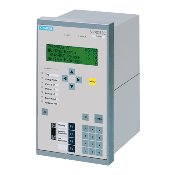
Hardware and Connections Version of 7SA6 for Panel Flush Mounting (Cubicle Mounting) ® The numerical Distance Protection SIPROTEC 7SA6 for panel and cubicle flush mounting is enclosed in a 7XP20 housing. 3 housing sizes are available, namely (of 19 inch). Housing size is provided with a four-line display. - Page 35 Hardware and Connections View of Front Panel with Four-Line Display (Housing Size SIPROTEC SIEMENS ERROR 7SA610 MAIN MENU 01/04 Annunciation Measurement MENU ENTER Annunciation Meas. Val. Trip log Figure 2-1 Front view of a 7SA61 (housing size ) for panel flush mounting or cubicle...
- Page 36 Hardware and Connections 7. 9-pin female D-subminiature connector ® This serial interface is for the connection of a local PC running DIGSI 8. LED key This key has the dual purpose of resetting latched LEDs and the latched contacts of output relays, as well as testing all of the LEDs. 9.
- Page 37 View of Front Panel The significance of the operating and display elements is the same as explained after with Four-Line Figure 2-1. However, 14 LEDs are freely configurable. Display (Housing Size SIPROTEC SIEMENS ERROR 7SA611 MAIN MENU 01/04 Annunciation Measurement...
- Page 38 View of Front Panel The significance of the operating and display elements is the same as explained with Four-Line after Figure 2-1. However, 14 LEDs are freely configurable. Display (Housing Size SIPROTEC SIEMENS ERROR 7SA6 MAIN MENU 01/04 Annunciation Measurement...
- Page 39 Hardware and Connections View of Front Panel with Graphic SIPROTEC SIEMENS Display ERROR 7SA631 (Housing Size Schlossplatz MENU 1000 A 21 kV Abzweig erden mit F4 CTRL ENTER Annunciation Local Meas. Val. Remote Trip log Test Normal Figure 2-4 Front view of a 7SA63, housing size...
- Page 40 13. Coverings for the screws that secure the front panel. View of Front Panel The significance of the operating and display elements is the same as explained after with Graphic Figure 2-4. Display (Housing Size SIPROTEC SIEMENS ERROR 7SA632 Schlossplatz MENU 1000 A 21 kV Abzweig erden mit F4...
- Page 41 Hardware and Connections View of Rear Panel Figure 2-6 shows a simplified view of the rear panel of a device with screw-type termi- (Housing Size nals. Rear view of a (terminal arrangement Figure 2-6 7SA6, housing size example only) 7SA6 Manual C53000-G1176-C156-2...
- Page 42 Hardware and Connections View of Rear Panel Figure 2-7 is a simplified view of the rear panel of the version of the device with screw- (Housing Size type terminals and optical fibre ports for the service interface at location B. Rear view of a (terminal arrangement Figure 2-7...
-
Page 43: Screw Terminal Connections
Hardware and Connections 2.1.2 Screw Terminal Connections The following must be distinguished in the case of connection via screw terminals: terminal plugs for voltage connections and terminal plugs for current connections. The terminal screws have a slot head for tightening or loosening with a flat screw driv- er, sized 6 ×... - Page 44 Hardware and Connections 8 terminal Figure 2-11 Terminal block of screw terminals for current connections — rear view The available poles are arranged into pole pairs, each containing two poles. In this manner, the two neighbouring terminals form one pair. Accordingly the current termi- nal module with 8 poles contains 4 pairs.
- Page 45 Hardware and Connections Connections to Ring-type and fork-type lugs may be used. To ensure that the insulation paths are Current Terminals maintained, insulated lugs must be used. Alternatively, the crimping area must be in- sulated with other methods, e.g. by covering with a shrink sleeve. The following must be observed: Connections with cable lugs: inner diameter of lugs, 5 mm;...
- Page 46 Hardware and Connections noted that all screws on the terminal module must be screws in before snapping the cover on. The terminal covering cap can simply be removed with a screw driver 6x1. There are two types of covering caps, as shown in Figure 2-13. Ordering information is provided in Section A.1 in the Appendix.
-
Page 47: Connections To Plug-In Terminals
Hardware and Connections 2.1.3 Connections to Plug-In Terminals Plug-in terminals are only available for voltage connections. Current connections are made with screw terminals on all 7SA6. Terminal Blocks for There are two versions of plug-in terminal blocks. They are shown in Figure 2-14. Voltage Connections 18 terminal... - Page 48 Hardware and Connections inside the 7SA6. Each common group can, for example, be used for signal multiplica- tion or as a common point for a signal (independent of the signals on the pin “a” termi- nals). Depending on the version of the terminal block, 18 or 12 common connections are available.
- Page 49 Hardware and Connections Figure 2-17 2-pin connector and 3-pin connector Ordering information for the pin connectors is provided in Section A.1 of the Appendix. The design of the pin connectors is such that only correct connections can be made. For example, the design of the 2-pin connector allows connection only to pins “a” and “b”.
-
Page 50: Connections To Optical Communication Interfaces
Hardware and Connections The following separation tool is needed to remove the contacts from the pin connec- tors: Type: 725840–1 from Messrs. Tyco Electronics AMP. The separation tool contains a small tube that is subject to wear. The tube can be or- dered separately: Type: 725841–1 from Messrs. - Page 51 Hardware and Connections Figure 2-19 Optical communication interfaces with caps Connections to Optical connector type: FC–connector Optical Communication Fibre type: Monomode Interfaces with 9/125 µm, λ = 1300 nm (approximately) FC–Connectors Wavelength: Allowable bending radius:For indoor cable = 5 cm (2 in) For outdoor cable r = 20 cm (8 in) 2-19...
-
Page 52: Connections To Electrical Communication Interfaces
Hardware and Connections 2.1.5 Connections to Electrical Communication Interfaces Electrical 9-pin D-subminiature female socket connectors are provided for all electrical commu- Communication nication interfaces of the 7SA6. The connector is illustrated in Figure 2-20. The pin as- Interfaces signments are described in Sub-section 8.2.1. Operating Interface Time Synchronization on the Front Side... -
Page 53: Connections To Analog Outputs
Hardware and Connections 2.1.6 Connections to Analog Outputs Connections 9-pin D-subminiature female socket connectors are provided for all analog outputs of the 7SA6. The connector is illustrated in Figure 2-21. The pin assignments are de- scribed in Subsection 8.2.1. Figure 2-21 9 pin D-subminiature connectors Connections to Standard 9-pin D-subminiature plug connectors per MIL–C–24308 and DIN 41652... -
Page 54: Version Of 7Sa6 For Panel Surface Mounting
Hardware and Connections Version of 7SA6 for Panel Surface Mounting ® The numerical Distance Protection SIPROTEC 7SA6 for surface mounting is en- closed in a 7XP20 housing. 2 housing versions are available, (of 19 inch). The device is fitted into a surface mounting housing. 2.2.1 Housing The housing consists of a rectangular tube with a rear plate and a front cover. - Page 55 Hardware and Connections View of Front Panel with Four-Line Display (Housing Size SIPROTEC SIEMENS ERROR 7SA610 MAIN MENU 01/04 Annunciation Measurement MENU ENTER Annunciation Meas. Val. Trip log 9 L+ L- 13 14 15 17 18 19 20 21 22 23 24 25 26...
- Page 56 Hardware and Connections function keys are programmable, and may be used to execute control functions such as closing or tripping circuit breakers. Next to the keypad, a labeling strip is provided on which the user-specified key functions may be written. 7.
- Page 57 View of Front Panel The significance of the operating and display elements is the same as explained after with Four-Line Figure 2-22. However, 14 LEDs are freely configurable. Display (Housing Size SIPROTEC SIEMENS ERROR 7SA611 MAIN MENU 01/04 Annunciation Measurement...
- Page 58 Hardware and Connections View of Front Panel The significance of the operating and display elements is the same as explained after with Four-Line Figure 2-22. Display (Housing Size SIPROTEC SIEMENS ERROR 7SA612 MAIN MENU 01/04 Annunciation Measurement MENU ENTER Annunciation Meas.
- Page 59 Hardware and Connections View of Front Panel with Graphic Display (Housing Size SIPROTEC SIEMENS ERROR 7SA631 Schlossplatz MENU 1000 A 21 kV Abzweig erden mit F4 CTRL ENTER Annunciation Local Meas. Val. Remote Trip log Test Normal 11 12 13 14 L+ L-...
- Page 60 Hardware and Connections tories, for displaying the lists of the event logs (F1), the operational measured val- ue (F2) and the trip logs of the last fault (F3). The key F4 is not allocated. All func- tion keys are freely configurable. Next to the keypad, a labeling strip is provided on which the user-specified key functions may be written.
-
Page 61: Screw Terminal Connections
Hardware and Connections View of Front Panel The significance of the operating and display elements is the same as explained after with Graphic Figure 2-25. Display (Housing Size SIPROTEC SIEMENS ERROR 7SA632 Schlossplatz MENU 1000 A 21 kV Abzweig erden mit F4... -
Page 62: Connections To Optical Communication Interfaces
Hardware and Connections Connections to Solid conductor or stranded wire with lugs can be used. Terminals The following specifications must be observed: Direct cable connections: solid or stranded conductor with connector sleeve conductor with cross-section of 0.5 mm to 7 mm (AWG 20 to 9). - Page 63 Hardware and Connections , channel D and E Housing for optical communication interfaces Housing for optical communication interfaces channel B and C Figure 2-27 Side view of 7SA6, panel surface mounting, possible optical communication in- terfaces A table indicating the available channel designations B to E is printed onto the inclined housing.
- Page 64 Hardware and Connections this purpose, the inclined housing features a DSUB-socket for electrical connection on channel B which can be converted externally to optical connection via a separate elec- tro-optical converter. Channel C Channel B Channel E Channel D Figure 2-29 Inclined housing with optical communication interface B and DSUB socket for Profibus interface Connections to...
- Page 65 Hardware and Connections Kanal C Kanal B Kanal E Kanal D Figure 2-30 Inclined housing with fibre-optic connections (channel D and E fitted) Connections to Optical connector type: FC–connector Optical Communication Fibre type: Monomode Interfaces with 9/125 µm, λ = 1300 nm (approximately) FC–Connectors Wavelength: Allowable bending radius:For indoor cable...
-
Page 66: Connections To Electrical Communication Interfaces
Hardware and Connections 2.2.4 Connections to Electrical Communication Interfaces Electrical 9-pin D-subminiature female socket connectors are provided for all electrical commu- Communication nication interfaces of the 7SA6. The connector is illustrated in Figure 2-31. The pin as- Interfaces signments are described in Subsection 8.2.1. Channel C Channel B Channel C... -
Page 67: Connections To Analog Outputs
Hardware and Connections 2.2.5 Connections to Analog Outputs Connections 9-pin D-subminiature female socket connectors are provided for all analog outputs of the 7SA6. The connector is illustrated in Figure 2-32. The pin assignments are de- scribed in Subsection 8.2.1. Channel C Channel B Channel E Channel D... -
Page 68: Version Of 7Sa6 With Detached Operator Panel
Hardware and Connections Version of 7SA6 with Detached Operator Panel ® The numerical Distance Protection SIPROTEC 7SA6 with detached operator panel is intended for mounting it into a low-voltage box. It consists of a device in a 7XP20 housing for surface mounting and a detached operator panel for mounting onto a mounting plate. - Page 69 View of Device and The following figure shows an 7SA6 device with detached operator panel, its housing Operator Control with plug-in terminals and communication cable. Element (Housing Size SIPROTEC SIEMENS ERROR 7SA641 Schlossplatz MENU 1000 A 21 kV Abzweig erden mit F4...
-
Page 70: Screw Terminal Connections
View of Device and The following figure shows an 7SA6 device with detached operator panel, its housing Operator Control with plug-in terminals and communication cable. Element (Housing Size SIPROTEC SIEMENS ERROR 7SA642 Schlossplatz MENU 1000 A 21 kV Abzweig erden mit F4... - Page 71 Hardware and Connections 18 terminal 12 terminal Figure 2-35 Connection plug module with screw terminals for voltage connections — rear view Figure 2-10 shows an example of the allocation of an individual screw terminals to their terminal numbers. connection terminal 1 connection terminal 2 Figure 2-36 Allocation of screw terminal to terminal number —...
- Page 72 Hardware and Connections The available poles are arranged into pole pairs, each containing two poles. In this manner, the two neighbouring terminals form one pair. Accordingly the current termi- nal module with 8 poles contains 4 pairs. In combination with the plug connection on the module side, these terminal pairs have an integrated short-circuiting function which short-circuits the two neighbouring cur- rent passages when the module is withdrawn.
- Page 73 Hardware and Connections Direct cable connections: solid or stranded conductor with connector sleeve; conductor with cross-section of 2.6 mm to 3.3 mm (AWG 14 to 12). When using one single conductor, the conductor end must be inserted such that it will be drawn into the contact cavity while tightening the screw.
- Page 74 Hardware and Connections Covering cap for Covering cap for 18 terminal voltage 12 terminal voltage connection terminal block or 8 Terminal Current connection terminal block Figure 2-39 Covering caps for terminal blocks with screw terminals 2.3.3 Connections to Plug-In Terminals Plug-in terminals are only available for voltage connections.
- Page 75 Hardware and Connections The system of numbers and letters used to designate the plug-in terminals is illustrat- ed in Figure 2-15. Plug-in terminal 1 Plug-in terminal 2 Figure 2-41 Correlation between plug-in terminals and connection numbers/letters Each plug-in terminal forms a complete set of connections that consists of three pins arranged as follows: Pin a: Signal connection...
-
Page 76: Connections To Plug-In Terminals
Hardware and Connections 12 terminal 18 terminal Signal connection Common connection Shielding connection Common connections, group 1 looped together Common connections, group 2 looped together Shielding connections looped together Figure 2-42 Schematic diagram of the plug-in terminal blocks Connections to Connections to plug-in terminals are made with pin connectors. -
Page 77: Connections To Optical Communication Interfaces
Hardware and Connections Use only flexible copper control wire! The following crimp connectors can be used: Tin-plated version: Diameter 0.5 mm to 1.0 mm e.g. Bandware 4000 pieces type: 0–827039–1 from Messrs. Tyco Electronics AMP Individual piece type: 0–827396–1 from Messrs. Tyco Electronics AMP Diameter 1.0 mm to 2.5 mm e.g. - Page 78 Hardware and Connections 2 channel 1 channel 1 channel Figure 2-44 Optical communication interfaces with protective caps Connections to Optical connector type: ST–connector Optical Communication Fibre type: Multimode graded-index (“G”) optical fibre Interfaces with G50/125 µm, ST–Connectors G62.5/125 µm, G100/140 µm λ...
- Page 79 Hardware and Connections Connections to Optical connector type: FC–connector Optical Communication Fibre type: Monomode Interfaces with 9/125 µm, λ = 1300 nm (approximately) FC–Connectors Wavelength: Allowable bending radius:For indoor cable = 5 cm (2 in) For outdoor cable r = 20 cm (8 in) 2-47 7SA6 Manual C53000-G1176-C156-2...
-
Page 80: Connections To Electrical Communication Interfaces
Hardware and Connections 2.3.5 Connections to Electrical Communication Interfaces Electrical 9-pin D-subminiature female socket connectors are provided for all electrical commu- Communication nication interfaces of the 7SA6. The connector is illustrated in Figure 2-20. The pin as- Interfaces signments are described in Sub-section 8.2.1. Operator Interface Time Synchronization on the Front Side... -
Page 81: Connections To Analog Outputs
Hardware and Connections 2.3.6 Connections to Analog Outputs Connections 9-pin D-subminiature female socket connectors are provided for all analog outputs of the 7SA6. The connector is illustrated in Figure 2-47. The pin assignments are de- scribed in Subsection 8.2.1. Figure 2-47 9 pin D-subminiature connectors Connections to Standard 9-pin D-subminiature plug connectors per MIL–C–24308 and DIN 41652... - Page 82 Hardware and Connections 2-50 7SA6 Manual C53000-G1176-C156-2...
-
Page 83: Initial Inspections
Initial Inspections This chapter describes the initial inspections that should be carried out upon recept of ® the SIPROTEC 4 device 7SA6. Unpacking and re-packing is explained. Visual and electrical checks that are appropriate for initial inspection are discussed. The electrical tests include navigating through the operating menus of the device us- ing the operator control panel on the front of the device, and the operator control win- ®... -
Page 84: Unpacking And Repacking
Initial Inspections Unpacking and Repacking The 7SA6 is packaged at the factory to meet the requirements of IEC 60255–21. Unpacking and re-packing must be done with usual care, without using force, and with appropriate tools. Visually check the device immediately upon arrival for correct me- chanical condition. -
Page 85: Inspections Upon Receipt
Initial Inspections Inspections upon Receipt 3.2.1 Inspection of Features and Ratings Ordering Number Verify that the 7SA6 has the expected features by checking the complete ordering number with the ordering number codes given in Sub-section A.1 of the Appendix. Also check that the required and expected accessories are included with the device. The ordering number of the device is on the nameplate sticker attached to the outside of the housing. -
Page 86: User Interface
Initial Inspections User Interface 3.3.1 Operation Using the Operator Control Panel Operator Control The device has a hierarchically structured operating tree, within which movements Panel and actions are made using the keys and the , and MENU ENTER CTRL keys on the front panel. The brief discussions below illustrate the navigation techniques using the integrated operations in the operator control panel. - Page 87 Initial Inspections SETUP/EXTRAS 05/06 --------------------- Date/Time –> Clock Setup –> Serial Ports –> Device-ID –> >MLFB/Version –> MLFB/VERSION 01/03 Contrast –> MLFB: 7SA6... 3HA1 BF–Nr.: 9811049704 MLFB/VERSION 02/03 Firmware: 4.00.18 Bootsystem: 1.00.04 Figure 3-2 Display of device-specific data — example Viewing Measured To view the measured values: Values...
-
Page 88: Operation Using Digsi ® 4
Initial Inspections Setting the Display If the image in the integrated LCD does not have satisfactory contrast, adjustments Contrast can be made. A stronger contrast serves, among other purposes, to improve the read- ability of the image from an angle. With increasing numbers, the contrast is increased and the picture gets darker. - Page 89 Initial Inspections ® Open the DIGSI 4 application in the PC. Generate a new project by clicking on File → New in the DIGSI ® 4–Manager menu bar. ® Figure 3-4 Dialogue box to open a new project in DIGSI Enter a name for the new project in the Name entry field (e.g.
- Page 90 Initial Inspections Figure 3-6 Plug & Play dialogue box for communication between device and PC A direct connection is then established (on-line), the data are exchanged between the ® PC and the device, and the initial screen for DIGSI 4 opens, as shown on Figure 3-7. By double clicking Online in the navigation window (left window), the structure opens (directory tree).
- Page 91 Initial Inspections ® Figure 3-8 DIGSI 4 — Viewing the secondary operating measured values — example A table of the secondary operating measured values appears, as shown in Figure 3-9. Since no measured AC currents or voltages are present at this time, all operating measured values are close to zero.
- Page 92 Initial Inspections ® Figure 3-10 DIGSI 4 — Operational messages window — example Press the key on the device; all LEDs should light while the key is pressed. The message “Reset LED” appears as the newest message as soon as the window is updated.
- Page 93 Initial Inspections Setting Date and To enter the date and time: Time Click on Device in the menu bar. See Figure 3-11. Select Set Clock. ® 4 — Selection of the option Set Clock Figure 3-11 DIGSI The dialog field Set clock & date in device opens. The field shows the present date and the approximate present time according to the device.
-
Page 94: Storage
Initial Inspections Storage If the device is to be stored, note: ® SIPROTEC 4 devices and associated assemblies should be stored in dry and clean rooms, with a maximum temperature range of –25° C to +55° C (–12° F to 131° F). See Sub-section 10.1.7 under Technical Data. -
Page 95: Siprotec
® SIPROTEC 4 Devices ® This chapter provides an overview of the family of SIPROTEC 4 devices and the in- tegration of the devices into power plants and substation control systems. Principle procedures are introduced for setting the devices, controlling primary equipment with the devices, and performing general operations with the devices. -
Page 96: General
® SIPROTEC 4 Devices General ® The SIPROTEC 4 family is an innovative product series of numerical protective and control devices with open communication interfaces for remote control and remote setting, ergonomically designed operator panels, and highly flexible functionality. 4.1.1 Protection and Control The devices utilize numerical measuring techniques. - Page 97 ® SIPROTEC 4 Devices To Network Control Centers Operation and Observation IEC 60870-5-101 SICAM WinCC DIGSI 4 DCF, GPS Time Synchronization SICAM SC IEC 60870-5-103 Profibus FMS Feeder Devices Profibus DP, DNP3.0 Figure 4-1 Integration of feeder devices in substation control system — example In the sample configuration in Figure 4-1, data transmitted from the feeder devices can be processed in the sub-station control device SICAM SC, displayed at the operating and observation station SICAM WinCC, and transferred by the remote terminal unit...
-
Page 98: Settings
® SIPROTEC 4 Devices ® The PROFIBUS DP protocol facilitates the connection of SIPROTEC –devices to SPS-based process control systems (e.g. SIMATIC S5/S7). The protocols DNP3.0 and MODBUS ASCII/RTU allow the connection to a wide range of control systems by other manufacturers. -
Page 99: Operator Control Facilities
The operating panel contains either a full graphical display or a four-line display, de- ® pending on the specific device of the SIPROTEC 4 family. Operating Panel with Four-Line Display SIPROTEC SIEMENS ERROR 7SA522 MAIN MENU 01/05 SIPROTEC SIEMENS ERROR... - Page 100 ® SIPROTEC 4 Devices The functions of the operating and display elements on the operator control panel are described below. Display Process and device information are displayed in the LCD display. Commonly dis- played information includes circuit breaker status, measured values, counter values, binary information regarding the condition of the device, protection information, gen- eral messages, and alarms.
-
Page 101: Digsi ® 4 Tool
® SIPROTEC 4 Devices ® 4.2.2 DIGSI 4 Tool ® DIGSI 4 uses the familiar Windows operating environment. ® User Guide In DIGSI 4 only the settings that are available within a specific device are shown in the specific windows. If a protective feature is changed from disabled to enabled in the Device Configuration, then the settings relevant to that feature become available. -
Page 102: Information Retrieval
® SIPROTEC 4 Devices Information Retrieval ® A SIPROTEC 4 device has an abundance of information that can be used to obtain an overview of the present and past operating conditions of the device and the portion of the power system being protected or controlled by the device. The information is represented in separate groups: Annunciations, Measurements,... -
Page 103: Annunciations
® SIPROTEC 4 Devices 4.3.1 Annunciations The scope of the indication (messages) that are given under Annunciation is deter- ® mined when settings for the configuration of functions are applied to the SIPROTEC device. ® The messages are divided into the following categories, and displayed using DIGSI or the operator control panel of the device: Event Log: Operating messages: independent of network faults, e.g. - Page 104 ® SIPROTEC 4 Devices ® Display on To display messages in the operating field of the SIPROTEC 4 device: the Device • Select Main Menu → Annunciation → e.g. Event Log or Trip Log. MAIN MENU 01/05 --------------------- >Annunciation –> >Measurement –>...
-
Page 105: Measurements
® SIPROTEC 4 Devices 4.3.2 Measurements The registered measured values are classified into the following categories for display ® in DIGSI 4 or on the operating field of the device: Primary values, based on the measured secondary values and the settings entered for the current transformers and voltage transformers. - Page 106 ® SIPROTEC 4 Devices ® Display on To display the measured values in the operating field of the SIPROTEC 4 device: the Device • Select Main Menu → Measurement → e.g. Operation. pri. MAIN MENU 02/05 --------------------- >Annunciation –> >Measurement –>...
-
Page 107: Oscillographic Fault Records
® SIPROTEC 4 Devices 4.3.3 Oscillographic Fault Records ® As an option, SIPROTEC 4 devices can have waveform capturing and event record- ing. Furthermore, the elements that are shown in the fault records can be selected by the user. ® The fault record data are retrieved from the device memory by DIGSI 4 and are stored as oscillographic records in standard COMTRADE format. -
Page 108: Control
® SIPROTEC 4 Devices Control ® The multiple application possibilities for SIPROTEC 4 devices allow an equally flex- ible concept for command processing and control. Remote If the device is integrated into a master control system, then command outputs can be remotely controlled via the system interface using telegrams from Higher-level control systems, or substation control devices such as SICAM SC. - Page 109 ® SIPROTEC 4 Devices The status of a primary switch can be read out on the display using BREAKER/SWITCH → Display (Figure 4-10). BREAKER/SWITCH 01/04 --------------------- >Display –> DISPLAY 01/03 >Control –> -------------------- >52Breaker OPEN Disc.Swit. CLOS Determining primary switch status using the operator control panel Figure 4-10 ®...
-
Page 110: Manual Overwrite / Tagging
® SIPROTEC 4 Devices Manual Overwrite / Tagging Manual Overwrite If the breaker/switch position is not available from the switch-gear, the status of the switchgear device can be manually set to the actual present position using the opera- tor control panel: Main Menu → Control → Breaker/Switch → Man. Over- write. -
Page 111: General About The Setting Procedures
® SIPROTEC 4 Devices General about the Setting Procedures ® The SIPROTEC 4 devices are delivered with standard default settings. Changes to ® the settings are done with DIGSI ® The setting procedure for a SIPROTEC 4 device consists of Overall Protection and Control Design: determining the functions that are to be used (device configuration), assigning the binary inputs, outputs, LEDs, buffers, system port, etc. - Page 112 ® SIPROTEC 4 Devices LOAD PARAMETER --------------------- ····················· ····················· ···· --------------------- Download active Screen of Device during Settings Transfer Figure 4-13 ® Setting Sequence When setting a SIPROTEC 4 device, adhere to the following sequence: Specify the interfaces, the device data, and the time synchronization, Determine the device functions to be used, Carry out routing Design the assignment of the inputs and outputs using the configuration matrix,...
- Page 113 ® SIPROTEC 4 Devices Settings for Setting changes to individual protective elements and functions can be done using the ® Protective operator control panel on the SIPROTEC 4 device. Elements Other settings such as input/output and device configuration can be viewed from the front panel, but not changed.
-
Page 114: Configuration Of The Scope Of Device Functions
® SIPROTEC 4 Devices Configuration of the Scope of Device Functions ® The individual devices within the SIPROTEC 4 family can be supplied with various protective functions. The ordering number of the device determines the available func- tions. The functions are specified more precisely through the process of enabling and disabling in the Device Configuration area of the settings. -
Page 115: Configuration Of Inputs And Outputs (Configuration Matrix)
® SIPROTEC 4 Devices Configuration of Inputs and Outputs (Configuration Matrix) A configuration matrix is used to determine processing of the binary inputs, outputs, LEDs, and indication buffers. ® Configuration is performed with DIGSI The configuration matrix is primarily divided into the following columns: Device functions Information, e.g. - Page 116 ® SIPROTEC 4 Devices ® Figure 4-17 DIGSI 4, Input/Output Masking with the Configuration Matrix, Example Filter Functions With the use of filters, either all information can be displayed or a selection can be done according to indications, commands, or measured values. Additionally, there is a filter setting that differentiates between information configured and not configured.
- Page 117 ® SIPROTEC 4 Devices ® SIPROTEC 4 device information can be connected in a user-specified manner using ® the programmable logic components of the DIGSI 4 CFC. For example, the user can implement interlocking checks, create grouped messages, or derive limit value viola- tion messages.
-
Page 118: Programmable Logic Cfc
® SIPROTEC 4 Devices Programmable Logic CFC ® ® The CFC program in DIGSI 4 can be used to create additional logic in SIPROTEC 4 devices. For example, special interlocking conditions for controlled equipment can be designed. Limit checks for measured values can be created, and corresponding control can be designed. - Page 119 ® SIPROTEC 4 Devices Figure 4-20 CFC Logic — example 4-25 7SA6 Manual C53000-G1176-C156-2...
-
Page 120: Power System Data
® SIPROTEC 4 Devices 4.10 Power System Data Power System In the window for Power System Data 1, important settings are entered that relate to Data 1 the power system and primary equipment connected to the device. The settings in- clude: system data such as frequency, voltage, etc. -
Page 121: Setting Groups
® SIPROTEC 4 Devices 4.11 Setting Groups ® A SIPROTEC 4 device has up to four setting groups A through D. The setting options for each group are the same; however, the applied settings can be, and are typically intended to be, different in each group. The active setting group can easily be changed while the device is in-service. -
Page 122: Siprotec ® 4 Devices
® SIPROTEC 4 Devices Settings Double click on a protective function shown in the listbox of Figure 4-22 to obtain a dialogue box for entering the settings associated with this function (Figure 4-23). ® Figure 4-23 DIGSI 4, entering settings for a protective function — example ®... -
Page 123: General Device Settings
® SIPROTEC 4 Devices 4.12 General Device Settings The settings of the display to show information of network faults on the LEDs and the ® ® LCD on the front of the SIPROTEC 4 device are defined in the DIGSI 4 window shown in Figure 4-25. -
Page 124: Time Synchronization
® SIPROTEC 4 Devices 4.13 Time Synchronization ® Time tracking in a SIPROTEC 4 device can be implemented using: DCF77 Radio Receiver (Time Signal from PTB Braunschweig), IRIG-B Radio Receiver (Time Signal from the global positioning satellite (GPS) sys- tem), signals via the system interface from, for example, a substation control system, radio clock using a system-specific synchronizer box, minute impulses on a binary input. -
Page 125: Serial Interfaces
® SIPROTEC 4 Devices 4.14 Serial Interfaces ® Devices in the SIPROTEC 4 family can be equipped with up to four serial interfaces. The system interface on the back panel of the device is for connection to a central master control system. Depending on the type and the version of the device the fol- lowing protocols are available: •... - Page 126 ® SIPROTEC 4 Devices To set the framing and baud rate: • Double click on Serial Ports in the data window and enter the specific settings in the window that follows. ® Figure 4-28 DIGSI 4, Interface Settings Window • Read-out on the Operator Control Panel ®...
-
Page 127: Passwords
® SIPROTEC 4 Devices 4.15 Passwords ® Passwords are assigned to a SIPROTEC 4 device to protect against unintended changes to the device or unauthorized operations from the device, such as switching. The following access levels are defined: Switching/tagging/manual overwrite, Non-interlocked switching, Test and diagnostics, Hardware test menus,... - Page 128 At delivery all passwords are set to 000000. Note: If the password for setting group switching has been forgotten, a temporary password can be received from Siemens. The temporary password can be used to define a new password for this function. ®...
- Page 129 Configuration Configuration is the process of customizing the relay for the intended application. To accomplish this, the following questions must be answered: • Which functions do you need? • Which information and measured quantities need to be retrieved via which inputs? •...
-
Page 130: Configuration
Configuration Configuration of Functions General The 7SA6 relay contains a series of protective and additional functions. The scope of hardware and firmware is matched to these functions. Furthermore, commands (con- trol actions) can be suited to individual needs of the protected object. In addition, indi- vidual functions may be enabled or disabled during configuration, or interaction be- tween functions may be adjusted. - Page 131 Configuration ® Figure 5-1 Device Configuration dialogue box in DIGSI 4 — example Before closing the dialogue box, transfer the modified functional setting to the relay by clicking on the item DIGSI → Device. The data is stored in the relay in a non-volatile memory buffer.
- Page 132 Configuration Note: When having changed address 110, first save the changes by clicking onto the OK button. Then open the dialogue box again, since other setting options depend on ad- dress 110. Different pickup modes can be selected for the Distance Protection. The characteris- tics of these modes are described in detail in Subsection 6.2.2.
- Page 133 Configuration ferred to as “inverse” may also be used as a fourth definite time stage Definite Time. Alternatively the earth fault protection function controlled by zero sequence voltage U0 inverse can be selected. The various characteristics are shown in the technical data.
-
Page 134: Settings
Configuration According to the order variant the device is provided with analog outputs (0 to 20 mA). 2 outputs can be located on Port B (Mounting location “B”), another 2 on Port D (mounting location “D”). In address 150 to 153 the user can select which analog val- ues shall be output. - Page 135 Configuration Addr. Setting Title Setting Options Default Setting Comments Earth Fault O/C Disabled Disabled Earth fault overcurrent Time Overcurrent Curve IEC Time Overcurrent Curve ANSI Time Overcurrent Curve Logarithmic Definite Time U0 inverse Teleprot. E/F Directional Comparison Pik- Disabled Teleprotection for Earth fault overcurr.
- Page 136 Configuration Addr. Setting Title Setting Options Default Setting Comments AnalogOutput B1 Disabled Disabled Analog Output B1 (Port B) IL2 [%] UL23 [%] |P| [%] |Q| [%] Fault location d [%] Fault location d [km] Fault location d [miles] Trip current Imax [primary] AnalogOutput B2 Disabled Disabled...
-
Page 137: Configuration Of The Binary Inputs And Outputs
Configuration Configuration of the Binary Inputs and Outputs General Upon delivery, the display on the front panel of the relay, some of the function keys, the binary inputs and outputs (output contacts) are assigned to certain information. These assignments may be modified, for most information, allowing adaptation to the local requirements. - Page 138 Configuration e.g. Isolation e.g. mcb switch (7SA6) (7SA6) Binary input Binary input (e.g. BI1) L– (e.g. BI 2) (system) (system) Binary input (e.g. BI 3) L– Double point indication (DP) Single point indication (SP) Figure 5-3 Input indications Additionally to the predefined input and output indications new customer specific indi- cations and even control commands for switching devices may be created.
- Page 139 Configuration Table 5-1 Most important command types C_D2 Double Command with Single With at least 3 without feedback CF_D2 Output (common to a bus) relays with feedback C_D4 Double Command with Double With 4 relays without feedback CF_D4 Output with feedback C_D12 Double Command with Double With 3 relays...
- Page 140 Configuration CLOSE TRIP Command Command C– Switching CLOSE TRIP C– Device L– Matrix Configuration: Figure 5-5 Double command with single contacts CLOSE TRIP Command Command C– Switching CLOSE TRIP Device C– L– Matrix Configuration: Figure 5-6 Double command with single contacts plus common contact In contrast to other output relays the relay common to a bus is allocated to different switching devices (see Figure 5-7).
- Page 141 Configuration CLOSE TRIP Command Command C–1 Switching CLOSE TRIP Device C–1 C–2 C–2 L– Matrix Configuration: Figure 5-8 Double command with double contacts (with 4 relays) CLOSE TRIP Command Command C– Switching CLOSE TRIP Device C– L– Matrix Configuration: Figure 5-9 Double command with double and single contacts (with 3 relays) For the motor control illustrated in Figure 5-10 the following can be realized: −...
- Page 142 Configuration Due to the hardware platform a double command with single output via 2 relays with one pair of contacts each can only be applied with restrictions. For this purpose use the 2 power relays provided for motor control (only available in device versions with power relays) (see Figure 5-11 and 5-12).
- Page 143 Configuration CLOSE TRIP L– Command Command C–2 C–1 C– Switching Device TRIP CLOSE Matrix Configuration: – – The relays characterized with a minus-symbol must not be connected in different way ! Figure 5-12 Single command with 2 outputs via 2 power relays with 2 contacts each (setting: “Double Command with Single Output”) - example 5-15 7SA6 Manual...
-
Page 144: Structure And Operation Of The Configuration Matrix
Configuration 5.2.2 Structure and Operation of the Configuration Matrix General This section deals with the structure and operation of the configuration matrix. The configuration matrix can be viewed without making any configuration changes. Infor- mation characteristics and configuration steps are described in Sub-section 5.2.3, and configuration is demonstrated in Sub-section 5.2.4. - Page 145 Configuration Information in the rows is assigned to appropriate interfaces in the columns via an en- try in the intersecting cell. This establishes which information controls which destina- tion, or from which source information is received. In the configuration matrix, not only the configuration is shown, but also the type of configuration.
- Page 146 Configuration Information Groups All information is organized into information groups. In addition to general relay infor- mation, information regarding individual device functions is also included. By clicking on an information group title area with the right mouse button, a context menu can be viewed, which contains information regarding the properties of that infor- mation group.
-
Page 147: Establishing Information Properties
Configuration − MVT Measured Value with Time, − LV Limit Value, − LVU Limit Value, User Defined. • Metered Values: − MVMV Metered Value of Measured Value, − PMV Pulse Measured Value. The information contains various properties depending on the information type, which are partially fixed and may be partially influenced. - Page 148 Configuration Output Indication (OUT) Figure 5-14 Information properties — example for the information type “Output Indication” (OUT) Internal Single Point Indication (IntSP) Figure 5-15 Information properties — example for the information type “Internal Single Point Indication” (IntSP) 5-20 7SA6 Manual C53000-G1176-C156-2...
- Page 149 Configuration Singe Point Indication (SP) Figure 5-16 Information properties — example for information type “Single Point Indication” (SP) Double Point In addition to the properties entered for single point indications, a “Suppress interme- Indication (DP) diate position” check box is available, which may be checked to suppress the interme- diate indication during operations.
- Page 150 Configuration For input indications (single point indications SP, double point indications DP), trans- Filtering / Contact former tap indication TxTap (if available), filter times may be entered (pick-up and Chatter Suppression drop-out delays) to suppress momentary changes in potential at the binary input (e.g. contact chatter), refer also to Figure 5-16 and 5-17.
- Page 151 Configuration The encoded transformer tap changer position bit pattern is transformed into digital values between 1 and 62. An unrecognized pattern is interpreted as position 63. The number of bits coincides with the number of the binary inputs to be configured, and limits the number of positions to be represented.
- Page 152 Configuration Figure 5-19 Information properties example for information type “Limit Value User Defined” (LVU) If, for example, a low current reporter should be established using the CFC logic, and the percentage of the measured current should be matched to a certain amp value, the following values are entered in window according to Figure 5-19: The Dimension is A (amps).
- Page 153 Configuration Figure 5-20 Information Properties, Example for Information Type “Pulse Metered Value” (PMV) 5-25 7SA6 Manual C53000-G1176-C156-2...
- Page 154 Configuration Figure 5-21 Information Properties Example for Information Type “Metered Value of Measured Value” (MVMV) The available information in the configuration matrix is determined by the device type Entering Your Own and the configured functional scope. If necessary, you may extend the configuration Information matrix to information groups or individual information defined and entered by yourself.
- Page 155 Configuration Figure 5-23 Entry of the name of a user defined information group — example Information may be entered into the new information group using the information cat- alog (Figure 5-24). The information catalog is found in the menu bar under the View option, or via an icon in the toolbar.
-
Page 156: Performing Configuration
Configuration open the context menu, and select Delete Group. A confirmation window will ap- pear (Figure 5-25). Figure 5-25 Confirmation window before deleting a user defined group Click Yes if you actually want to delete the group. Note: When deleting a group, all information definitions within this group will be deleted. To delete individual entries, click under Information in the line with the entry to be deleted. - Page 157 Configuration In addition, a single point indication cannot be configured to a binary input and to CFC as a source at the same time. In this case, an error message would be displayed. Click on OK, and select another configuration. Error message resulting from double configuration Figure 5-26 If a double point indication (DP) is configured to one binary input (e.g.
- Page 158 Configuration Figure 5-27 Selecting a function key as an information source — example Configuring CFC as If certain information should be created as a result of the implementation of a user de- a Source fined logic function (CFC), this information must appear in the matrix as a source from CFC.
- Page 159 Configuration Example: Double Command with 2 relays (acc. Table 5-1) Figure 5-28 Window information catalog (example for different command types) If a command with multiple outputs is configured, all binary outputs required in the ma- trix for the configuration are automatically defined. If one of these outputs is de-con- figured, all other binary outputs associated with the command will be automatically de- configured.
- Page 160 Configuration Figure 5-29 Dialogue box: object properties for a command with feedback The conditional checks that should be conducted before execution of a switching com- mand can also be defined: • Substation interlocking: interlocking of substations is carried out (configuration via a substation) •...
- Page 161 Configuration Please be aware of the fact that also pickups from the overload protection or the sensitive earth current supervision can cause and maintain a fault and therefore block a close command. When resetting the interlocking also take into considera- tion that the automatic reclosure lockout for motors in this case does not automati- cally negate a close command sent to the motor.
- Page 162 Configuration Configuring the The information listed in Table 5.6 can be allocated according to the type of the system System Interface as interface. Setting an „X“ in the matrix cell the information is transferred via the system a Destination interface to its connected components. Tabelle 5-3 Overview of indications via the system interface System Interface →...
- Page 163 Configuration Configuring the User defined pulse values and metered values derived from the measured values may Metered Value be configured into the metered value window so that they may be displayed at the front Window as a Desti- relay panel. They are then available in the corresponding measured value window in nation the display of the device.
-
Page 164: Transferring Metered Values
Configuration 5.2.5 Transferring Metered Values ® The transferring of metered values from the buffer of a SIPROTEC -device or substa- tion controller may be performed both cyclically and/or by external polling. In the configuration matrix, click on Options and then on Restore Metered Val- ues. -
Page 165: Settings For Contact Chatter Blocking
Configuration 5.2.6 Settings for Contact Chatter Blocking Contact Chatter The contact chatter filter checks whether the number of condition changes at a binary Suppression input exceeds a preset value during a predetermined time interval. If this occurs, the binary input will be blocked for a certain time, so the event list does not contain a large number of unnecessary entries. - Page 166 Configuration The settings for the monitoring criteria of the chatter blocking feature are set only once for all binary inputs; however, the status of the chatter suppression can be set individ- ually for each binary input. See “Filtering/Contact Chatter Suppression” in Subsection 5.2.3.
-
Page 167: Creating User Defined Functions With Cfc
Configuration Creating User Defined Functions with CFC General The 7SA6 relay is capable of implementing user defined logic functions which may be processed by the relay. This CFC feature (Continuous Function Chart) is needed to process user defined supervision functions and logic conditions (e.g. interlocking con- ditions for switching devices) or to process measured values. - Page 168 Configuration task level Figure 5-34 Establishing the Within the Run Sequence menu, select Edit, and then Predecessor for In- stallation, to ensure that the function modules selected from the library will be im- plemented into the desired task level (Figure 5-35). task level Figure 5-35 Assignment of function modules to the selected...
- Page 169 Configuration task level Table 5-4 Selection guide for function modules and Run-Time Level Function Modules Description MW_BEARB PLC1_BEARB PLC_BEARB SFS_BEARB Meter processing Slow PLC Fast PLC Interlocking CMD_INF Test – – – CONNECT Connection – D_FF D-flipflop – DI_TO_BOOL Double point to boolean, –...
- Page 170 Configuration (OS4 in the diagram) may control an output relay, for example, and can create entries in the message buffers, depending on the preset configuration. Configuring and The default run-time sequence is determined by the sequence of the insertion of the Connecting logic modules.
- Page 171 Configuration If the link line display becomes unwieldy or impossible because of space limitations, the CFC editor creates a pair of connectors (target icons) instead. The link is recog- nizable via correlated numbering (see Figure 5-39). Connector Figure 5-39 Connector Events Events (SP_Ev, DP_Ev) are not suitable for processing in CFC, and should therefore not be used as input signals.
- Page 172 Configuration Table 5-6 Processing times in TICKS required by the individual elements Individual Element Amount of TICKS Module, basic requirement each input more than 3 inputs for generic modules Connection to an input Connection to an output signal Additional for each configuration sheet The utilized processor capacity which is available for the CFC can be checked under Option →...
- Page 173 Configuration A few examples are given below. Example 1 (MW): A configuration for low-current monitoring alarm (see Figure 5-42) which can be pro- Low Current duced using CFC, should be a first example. This element may be used to detect op- Monitor eration without load, or to recognize open circuited conditions.
- Page 174 Configuration • The number of inputs of the AND gate is increased to 7. • The CLOSE indications from the circuit breaker (CB) and from the grounding switch (GS) are supplied to the inputs of the NOR functions. • The OPEN indications from the circuit breaker (CB) and from the grounding switch (GS) are supplied to the inputs of the AND function.
- Page 175 Configuration CB TRIP ≥1 Circuit Breaker Protection TRIP Operation >Test Oper. Test Oper. Additional logic as an example for a PLC_1 event-driven logic condition Figure 5-44 5-47 7SA6 Manual C53000-G1176-C156-2...
-
Page 176: Establishing A Default Display
Configuration Establishing a Default Display The default display is the display appearing automatically after the initialization of the processor system. There are two types of displays, the 4-line LC display and the graphic display. 4-line LC Display Under normal conditions, the so-called default display is the default image in the relay display. - Page 177 Configuration column B and sub-column D must have been linked. A cross in the small box will en- able the link. A library is provided which contains symbols for circuit breakers, isolation switches, and grounding switches, and other devices. The standard setup may be modified, at ®...
- Page 178 Configuration Figure 5-46 Standard default display after opening the Display Editor • The information corresponding to the equipment and configured previously in the configuration matrix can now be selected in a Link dialog window (see Figure 5- 47), from which the user may click on the desired option and confirm with OK. In this manner, the user may link the graphical diagram with configuration settings.
- Page 179 Configuration • Check the finished default display. The grid may be hidden by clicking View → Grid, equipment may be selected (brought to the front) by clicking View → Make active, and a view of the overall relay with default display may be selected by clicking View →...
-
Page 180: Draft Of A Feeder Control Display
Configuration Draft of a Feeder Control Display General The feeder control display is used to visualize the switch positions and to control the Information switching objects. That is why only the objects relevant for the switching process are usually displayed while measured values and such have been omitted. The feeder control display must be selected. - Page 181 Configuration Proceed as follows: • If you saved the default display as a template and want to use it as basis for the control display, open the template via Display → Template → Open... into an empty control display. • As the switching devices in the bay are to be controlled via the feeder control dis- play, you need to make the respective device controllable for the operator.
-
Page 182: Serial Interfaces
Configuration Serial Interfaces Note: The protection data interfaces for protection transmission are described in Section 6.4 in the protection functions. The device contains one or more serial interfaces: an operator interface integrated into the front panel, and — depending on the model ordered — a service interface and a system interface for connection of a central control system. - Page 183 Configuration occurs during communication with the device. In order to modify these values, enter an integer value for RQ 1, between 200 and 9999, and for RQ 2, from 0 to 9999. Service and Opera- Settings for the interfaces at the device can performed in these tabs. The link address- es and maximum message gap appear in the Service Interface and Operator tor Interface Interface tab besides the settings for data format and transfer speed (example Fig-...
- Page 184 Configuration Other Interfaces Enter specific settings and addresses to identify devices in the other tabs, if neces- sary, or check the preset values. Device addresses are used by the system to identify each device and must be unique throughout the substation. Detailed instructions for setting the interfaces are available ®...
- Page 185 Configuration FRONT PORT 01/04 --------------------- >Phys.Addr. >>>>>1 >Baudrate 38400 Baud Parity 8E1 (DIGSI) Figure 5-54 Reading and setting the front interface at the device panel — example The type and number of system interface(s) is dependent on the device type and ver- sion and might be completely missing.
-
Page 186: Date And Time Stamping
Configuration Date and Time Stamping Integrated date and time stamping allows an exact evaluation of the sequence of events (e.g. event logs and trip logs or limit violations). The following clock settings are available: • Internal RTC clock (Real Time Clock), •... - Page 187 Configuration To open the Time Synchronization & Format window, the user should double- click on Time Synchronization. See Figure 5-57. ® Figure 5-57 Dialogue box for time synchronization and format in DIGSI Here you may select the time standard for internal time stamping. For the master device you may select from the following modes: Table 5-7 Operating modes for time synchronization...
- Page 188 Configuration has failed, this RTC is the first synchronization source for the internal clock, independ- ent of operating mode selected. In Internal mode, the system time is controlled using only the RTC as the synchro- nization source. It may be set manually. The procedure for manual date/time setting is given in Section 7.2.1.
- Page 189 Configuration After the “Time interruption ON” message, the you must take into account that Operating Messag- es from the Timing the clock will jump. This message is issued under the following circumstances: System − if a synchronization interruption lasts longer than the tolerance time interval men- tioned above, or as mentioned above, if the synchronization mode is changed;...
- Page 190 Configuration 5-62 7SA6 Manual C53000-G1176-C156-2...
-
Page 191: Functions
Functions ® This chapter describes the numerous functions available in the SIPROTEC 7SA6 re- lay. The setting options for each function are defined, including instructions for report- ing setting values and formulae where required. General Distance Protection 6-29 Measures to Be Taken in Case of Power Swings (optional) 6-72 Protection Data Interfaces and Protection Data Topology (optional) 6-78... -
Page 192: General
Functions General A few seconds after the device is switched on, the initial display appears in the LCD. Depending on the device version either measured values (four-line display) or a sin- gle-phase switching diagram of the feeder status (graphic display) is displayed in the 7SA6. - Page 193 Functions Settings are selected using the keys. When the key is pressed, the ENTER user is prompted for a password. The user should enter Password No. 5 and then press the ENTER key. The current value of the setting appears in a text box, with a blink- ing text insertion cursor.
- Page 194 Functions Exiting the If an attempt is made to exit setting modification mode using the key or the key, MENU the message Are you sure? will be displayed followed by the responses Yes, No, Setting Mode and Escape (see Figure 6-4). If the response Yes is selected, modification of settings can be confirmed by pressing the key.
- Page 195 Functions the dialogue box (e.g., in Figure 6-6, tabs exist for Power System, CT’s, VT’s, and Breaker). ® Figure 6-6 Power system data dialogue box in DIGSI 4 — example The left column of the dialogue box (identified as the No. column) contains the four- digit address number of the setting.
- Page 196 Functions To acknowledge the message, click OK, and the original value reappears. A new entry can be made or another setting value can be modified. Primary or Setting values can be entered and displayed in primary terms or secondary terms, as ®...
-
Page 197: Power System Data 1
Functions 6.1.1 Power System Data 1 Some system and plant data are required by the device, so that it may adapt its func- tions to these data, according to its mode of operation. Amongst others, the plant and instrument transformer ratings, polarity and termination of the measured values, pa- rameters of the circuit breaker, etc. - Page 198 Functions When connected to the e-n winding of a set of voltage transformers, the voltage transformation ratio of the voltage transformers is usually: ⁄ ⁄ Nprim Nsec Nsec ----------------- - --------------- - --------------- - In this case the factor Uph / Udelta (address 0211, matching ratio for the sec- ondary nominal voltages of phase voltage transformers and open-delta voltage) must be set to 3/√3 = √3 ≈...
- Page 199 Functions Address 215: U-line / Usync = 100 V/ 110 V = 0.91 Busbar 400 kV 400 kV 110 V (any voltage) 400 kV/220 kV sync 220 kV/100 V U4 transformer = Usync transf. Usync connect = L1–L3 ϕ Upp-Uline = 210° U-line / Usync = 0,91 Feeder 220 kV...
- Page 200 Functions Ratio of earth current transformer ⁄ ----------------------------------------------------------------------------------------------------- - ph CT Ratio of phase current transformers This is independent on whether the device has a normal measured current input for or a sensitive measured current input for I (for sensitive earth fault detection in non-earthed systems) Example: Phase current transformers 500 A/5 A...
- Page 201 Functions Address 235 PHASE SEQ. is used to establish the phase rotation. The preset phase Phase Rotation L1 L3 L2 L1 L3 L2 sequence is “ ”. For systems that use a phase sequence of “ ”, ad- dress 235 must be set accordingly. Address 236 Distance Unit corresponds to the units of length (miles or km) ap- Units of Length plicable to fault locating.
- Page 202 Functions Addr. Setting Title Setting Options Default Setting Comments Unom PRIMARY 1.0..1200.0 kV 400.0 kV Rated Primary Voltage Unom SECON- 80..125 V 100 V Rated Secondary Voltage (L-L) DARY CT PRIMARY 10..5000 A 1000 A CT Rated Primary Current CT SECONDARY CT Rated Secondary Current U4 transformer not connected...
- Page 203 Functions Addr. Setting Title Setting Options Default Setting Comments T-CBtest-dead 0.00..30.00 sec 0.10 sec Dead Time for CB test-autore- closure 6-13 7SA6 Manual C53000-G1176-C156-2...
-
Page 204: Setting Groups
Functions 6.1.2 Setting Groups Purpose of Setting A setting group is a collection of setting values to be used for a particular application. Groups In the 7SA6 relay, four independent setting groups (A to D) are possible. The user can switch between setting groups locally, via binary inputs (if so configured), via the op- erator or service interface using a personal computer, or via the system interface. - Page 205 Functions The next step is to highlight the name of setting group in the list into which the setting values should be copied. Go to the menu bar, click on Edit and select Paste. A con- firmation box will appear (see Figure 6-11). Select Yes to copy the setting values. Note: All existing setting values in the setting group that has been copied to will be overwrit- ten.
-
Page 206: Settings
Functions 6.1.2.1 Settings Addr. Setting Title Function Setting Options Default Setting CHANGE Change Group Group A Group A Group B Group C Group D Binary Input Protocol 6.1.2.2 Information Overview FNr. Setting Title Default Setting >Set Group Bit0 >Setting Group Select Bit 0 >Set Group Bit1 >Setting Group Select Bit 1 Group A... -
Page 207: General Protection Data
Functions 6.1.3 General Protection Data General protection data (P.System Data 2) includes settings associated with all functions rather than a specific protective or monitoring function. In contrast to the Power System Data 1 (P.System Data 1) as discussed in Sub-section 6.1.1, these settings can be changed over with the setting groups. - Page 208 Functions 1110 or 1112 or the line length in address 1111 or 1113 have been entered, the line data must be entered again for the revised unit of length. ® When entering the parameters with a personal computer and DIGSI 4 the values may optionally also be entered as primary values.
- Page 209 Functions Resistance ratio: Reactance ratio: æ ö æ ö ⋅ ⋅ -- - -- - ------ - ------ - 1 ------ - ------ 1 – – è ø è ø Whereby the following applies — Zero sequence resistance of the line —...
- Page 210 Functions These values may either apply to the entire line length or be based on a per unit of line length, as the quotients are independent of length. Furthermore it makes no difference if the quotients are calculated with primary or secondary values. For overhead lines it is generally possible to calculate with scalar quantities as the angle of the zero sequence and positive sequence system only differ by an insignifi- cant amount.
- Page 211 Functions K0 (> Z1) and 1123 AngleI K0(> Z1) apply to the remaining zones Z1B and Z2 up to Z5 (as seen from the relay location). Note: If a combination of values is set which is not recognized by the device, it operates with 0°...
- Page 212 Functions The current ratio may also be calculated from the desired reach of the parallel line compensation and vice versa. The following applies (refer to Figure 6-12): x l ⁄ -- - ------------------------ - -------- ----------------- - 2 x l ⁄ –...
- Page 213 Functions In address 1134 Line Closure the criteria for the internal recognition of line ener- gization are determined. In the case of only with ManCl only the manual close sig- nal derived via binary input is used to recognize the circuit breaker closing condition. With the setting I OR U or ManCl the measured currents or voltages are used as an additional criterion to recognise energization of the line.
- Page 214 Functions With the setting with PICKUP every pickup in more than one phase leads to three- pole coupling of the trip outputs, even if only a single-phase earth fault is situated with- in the tripping area, and further faults only affect the higher zones, or are located in the reverse direction.
- Page 215 Functions L1–E L2–E Multiple fault on a double-circuit line next to a generato Figure 6-14 Address 1156A Trip2phFlt determines that the short-circuit protection functions perform only a single-pole trip in case of isolated two-phase faults (clear of ground), provided that single-pole tripping is possible and permitted. This allows a single-pole rapid automatic reclosure cycle for this kind of fault.
- Page 216 Functions Addr. Setting Title Setting Options Default Setting Comments 1118 RE/RL(Z1B...Z5) -0.33..7.00 1.00 Zero seq. comp.factor RE/RL for Z1B...Z5 1119 XE/XL(Z1B...Z5) -0.33..7.00 1.00 Zero seq. comp.factor XE/XL for Z1B...Z5 1120 K0 (Z1) 0.000..4.000 1.000 Zero seq. comp. factor K0 for zone Z1 -135.00..135.00 °...
- Page 217 Functions 6.1.3.2 Information Overview F.No. Alarm Comments >CB Aux. L1 >Circuit breaker aux. contact: Pole L1 >CB Aux. L2 >Circuit breaker aux. contact: Pole L2 >CB Aux. L3 >Circuit breaker aux. contact: Pole L3 >CB 3p Closed >CB aux. contact 3pole Closed >CB 3p Open >CB aux.
- Page 218 Functions F.No. Alarm Comments Relay TRIP 3ph. Relay TRIP command Phases L123 Definitive TRIP Relay Definitive TRIP CB Alarm Supp CB alarm suppressed IL1 = Primary fault current IL1 IL2 = Primary fault current IL2 IL3 = Primary fault current IL3 PU Time Time from Pickup to drop out TRIP Time...
-
Page 219: Distance Protection
Functions Distance Protection Distance protection is the main function of the device. It is characterized by high meas- uring accuracy and the ability to adapt to the given system conditions. It is supplement- ed by a number of additional functions. 6.2.1 Earth Fault Recognition 6.2.1.1... - Page 220 Functions Negative Sequence On long, heavily loaded lines, the earth current measurement could be overstabilized Current 3I by large currents (ref. Figure 6-15). To ensure secure detection of earth faults in this case, a negative sequence comparison stage is additionally provided. In the event of a single-phase fault, the negative sequence current I has approximately the same magnitude as the zero sequence current I...
- Page 221 Functions 1203 3I0> ≥1 earth fault 3V0> 1204 3U0> Figure 6-17 Logic of the earth fault recognition The earth fault recognition is modified during the single-pole open condition with Earth Fault Recognition during single-pole automatic reclosure in an earthed system (Figure 6-18). In this case, the Single-Pole Open magnitudes of the currents and voltages are monitored in addition to the angles be- Condition...
-
Page 222: Setting Of The Parameters For This Function
Functions 6.2.1.2 Setting of the Parameters for this Function In systems with earthed star-point, the setting 3I0> Threshold (Address 1203 ) is set somewhat below the minimum expected earth short-circuit current. 3 I is defined as the sum of the phase currents | I |, which equals the star-point current of the set of current transformers. -
Page 223: Voltage-Dependent Current Fault Detection U/I
Functions eter 1ph FAULTS (address 1630A ) according to Table 6-2. In the non-earthed net- work, the phase–to–phase loop is always selected for single–phase pick-up without earth-fault detection. The phases that have picked-up are signalled. If an earth fault has been detected, it is also indicated. - Page 224 Functions Load arrea U(I>>) U(I>) Short-circuit area Iph> Iph>> Figure 6-19 U/I characteristic The setting 1601 ( PROG U/I ) determines if the phase–earth loops or the phase– Pick-up Mode phase loops are always valid or if this depends on the earth-fault detection according to Section 6.2.1.
- Page 225 Functions When evaluating phase–phase loops, the sensitivity towards phase–phase faults is particularly high. In extensive compensated networks this selection is advantageous because it excludes pick-up as a result of single earth faults on principle. With two- and three-phase faults it automatically adapts to the prevailing infeed conditions, i.e. in the weak-infeed operation mode it becomes more current-sensitive, with strong in- feed and high load currents the pick-up threshold will be higher.
-
Page 226: Voltage And Phase-Angle Dependent Current Fault Detection U/I/J
Functions Table 6-6 Loop and phase indication for single–phase U/I pick-up; Phase–earth voltage program in the event of earth faults, I>> without earth faults (address 1601) Pick-up Measured Measured Earth–fault Parameter Valid Signalled 1Ph FAULTS module current voltage detection loop Phase(s) L1–E L1–E... -
Page 227: Applying The Function Parameter Settings
Functions settings which determine the geometry of the current/voltage characteristic. The an- gle-dependent area which is shaded dark grey within the short-circuit angle area can either have an effect in forward direction (in direction of line) or in both directions (set- table). - Page 228 Functions and for phase–to–phase measuring loops separately. Address 1601 PROGAM U/I states which loop voltages shall apply to phase–to–earth ( Ph-E: ) and which ones to phase–to–phase ( Ph-Ph: ). In networks with earthed star point, a selection using U with earth faults and Ph–E with non-earthed faults is often preferred (address 1601 PROGAM U/I =...
- Page 229 Functions (address 1611 ) is set to below the minimum short-circuit current (approx. 10 %). This also applies to the phase currents during earth faults or double earth faults. In address 1630 1ph FAULTS you can choose whether a phase–to–earth loop shall be selected in an earthed network during single–phase pickup without earth current –release).
-
Page 230: Settings
Functions Angular If a distinction between short circuit and load conditions is not always possible using Dependence the U/I characteristic which is independent of the phase angle, the angular dependent section d-e can additionally be used. This is required for long lines and section of lines with intermediate infeed in combination with small source source impedances. -
Page 231: Information Overview
Functions ® Addresses which have an „A“ attached to its end can only be changed with DIGSI in “ Additional Settings “. Addr. Setting Title Setting Options Default Setting Comments 1601 PROGAM U/I Ph-E: Uphe/ Ph-Ph: Uphph Ph-E: Uphe/ Ph-Ph: Pickup program U/I Ph-E: Uphph/Ph-Ph: Uphph Uphph... -
Page 232: Calculation Of The Impedances
Functions 6.2.3 Calculation of the Impedances 6.2.3.1 Method of Operation A separate measuring system is provided for each of the six possible impedance loops L1–E, L2–E, L3–E, L1–L2, L2–L3, L3–L1. The phase-earth loops are evaluated when an earth fault detection according to section 6.2.1 is recognized and the phase current exceeds a settable minimum value Minimum Iph>... - Page 233 Functions Measuring System x–y x–y –L 1202 Iph> > & > from state recognition Figure 6-23 Logic of the phase-phase measuring system Phase–Earth Loops For the calculation of the phase-earth loop, for example during a L3–E short-circuit (Figure 6-24) it must be noted that the impedance of the earth return path does not correspond to the impedance of the phase.
- Page 234 Functions (parallel line) measuring syst. x–E x–E –E 1202 Iph> > earth fault recognition & from state recognition Figure 6-25 Logic of the phase-earth measuring system Unfaulted Loops The above considerations apply to the relevant short-circuited loop. A pick-up with the current-based fault detection modes (I, U/I, U/I/ ϕ...
- Page 235 Functions Double Earth- In systems with earthed starpoint (effective or low-resistant), each contact of a phase Faults in Earthed with earth results in a short-circuit condition which must be isolated immediately by the closest protection systems. Fault detection occurs in the faulted loop associated with Systems the faulted phase.
- Page 236 Functions Double Earth- In isolated or resonant-earthed networks a single earth fault does not result in a short Faults in circuit current flow. There is only a displacement of the voltage triangle (Figure 6-26). For the system operation this state is no immediate danger. The Distance Protection Non-earthed Sys- tems must not pick up in this case even though the voltage of the phase with the earth fault...
- Page 237 Functions Table 6-8 lists all measured values used for the distance measuring in isolated or res- onant-earthed systems. Table 6-8 Evaluation of measured loops for a multiple pick-up in non-earthed systems Fault detection Evaluated Setting Loops Loop(s) Parameter 1221 PHASE PREF.2phe = L1–E, L2–E, (L1–L2) L1–E L3 (L1) acyclic...
- Page 238 Functions ground below the line. These line parameters are input to the device — along with all the other line data — during the parameterisation of the device. The line impedance is calculated with the equation below similar to the calculation shown earlier. L3–E -------------------------------------------------------------------------------- ⁄...
-
Page 239: Applying The Function Parameter Settings
Functions ENABLE Z1B 3611 ≥1 Z1B instantaneous. 1232 SOTF zone Z2 instantaneous. Inactive Zone Z1B „1“ Z3 instantaneous. ≥1 & PICKUP Z4 instantaneous. SOTF Op. mode & Z5 instantaneous. Figure 6-28 Circuit breaker closure onto a fault 6.2.3.2 Applying the Function Parameter Settings The distance protection can be switched on or off with the parameter in address 1201 General Function FCT Distance ON/OFF... - Page 240 Functions The 7SA6 enables the user to detect all foot points of a multiple earth fault. PHASE PREF.2phe = All loops means that each earth fault point on a protected line is switched off independent of the preference. It can also be combined with a different preference.
-
Page 241: Settings
Functions current transformers600 A/5 A voltage transformers110 kV/0.1 kV The resulting minimum load impedance is therefore: ⋅ 0.9 110 kV 108.87 Ω ------------------------ - -------------------------- Load prim ⋅ ⋅ 3 525 A L max ® When applying the settings with a personal computer and DIGSI 4 these values may be entered as primary values. -
Page 242: Information Overview
Functions Addr. Setting Title Setting Options Default Setting Comments ϕ load (Ø-E) 20..60 ° 45 ° 1242 PHI load, maximum Load Angle (ph-e) 0.100..250.000 Ohm; ∞ ∞ Ohm 1243 R load (Ø-Ø) R load, minimum Load Impe- dance (ph-ph) ϕ load (Ø-Ø) 20..60 °... - Page 243 Functions F.No. Alarm Comments 3655 DisErrorK0(>Z1) Setting error K0(>Z1) or Angle K0(>Z1) 3671 Dis. PICKUP Distance PICKED UP 3672 Dis.Pickup L1 Distance PICKUP L1 3673 Dis.Pickup L2 Distance PICKUP L2 3674 Dis.Pickup L3 Distance PICKUP L3 3675 Dis.Pickup E Distance PICKUP Earth 3681 Dis.Pickup 1pL1 Distance Pickup Phase L1 (only)
- Page 244 Functions F.No. Alarm Comments 3717 Dis.Loop L23<-> Distance Loop L23 selected non-direct. 3718 Dis.Loop L31<-> Distance Loop L31 selected non-direct. 3719 Dis. forward Distance Pickup FORWARD 3720 Dis. reverse Distance Pickup REVERSE 3741 Dis. Z1 L1E Distance Pickup Z1, Loop L1E 3742 Dis.
-
Page 245: Distance Protection With Polygonal Tripping Characteristic (Optional)
Functions F.No. Alarm Comments 3813 Dis.TripZ1B1p Distance TRIP single-phase Z1B 3825 DisTRIP3p.Z1Bsf DisTRIP 3phase in Z1B with single-ph Flt 3826 DisTRIP3p Z1Bmf DisTRIP 3phase in Z1B with multi-ph Flt. 3816 Dis.TripZ2/1p Distance TRIP single-phase Z2 3817 Dis.TripZ2/3p Distance TRIP 3phase in Z2 3818 Dis.TripZ3/T3 Distance TRIP 3phase in Z3... - Page 246 Functions Line Characteristic α ϕ Load Area Load Area Figure 6-29 Polygonal characteristic Direction For each loop an impedance vector is also used to determine the direction of the short- Determination circuit. Usually similar to the distance calculation, Z is used. However, depending on the “quality”...
- Page 247 Functions L3–L1 – U L1–L2 L3–L1 L1–L2 L2–L3 L2–L3 a) Phase–earth loop (L1–E) b) Phase–phase loop (L2–L3) Figure 6-30 Direction determination with quadrature voltages Table 6-9 Allocation of the measured values for the direction determination Measured current Short-circuit loop Quadrature Loop (direction) voltage...
- Page 248 Functions A non-directional zone has no directional characteristic. The entire tripping area ap- plies here. “non-directional” “forward” “reverse” “non-directional” ) also applies to “Non-Directional” Figure 6-31 Directional characteristic in the R–X–diagram Characteristics of The theoretical steady-state directional characteristic shown in Figure 6-31 applies to the Directional faulted loop voltages.
- Page 249 Functions 7SA6 6-32a “forward” “forward” “reverse” “reverse” 6-32b 6-32c Figure 6-32 Directional characteristic with quadrature or memorized voltages Using the fault detection modes I , U/ I or U/ I / ϕ according to Subsection 6.2.2 the im- Pick-up and pedances, that were calculated from the valid loops, are assigned, after the pick-up, Assignment to the Polygons...
-
Page 250: Applying The Function Parameter Settings
Functions Dis switched off ≥1 Dis blocked PS blocking Dis FD forward & & ≥1 release of Z1 & Dis FD reverse & 1301 Op. mode Z1 forward reverse „1“ non-directional further inactive zones Figure 6-33 Release logic for a zone (example for Z1) In total the following zones are available: Independent zones: •... - Page 251 Functions ® When entering the relay parameters with a personal computer and DIGSI 4 it can be selected whether the settings are entered as primary or secondary values. In the case of parameterization with secondary quantities, the values derived from the grading coordination chart must be converted to the secondary side of the current and voltage transformers.
- Page 252 Functions care should however be taken that an arc fault on the local cable termination is inside the set resistance of the first zone. The resistance of the line need not be taken into consideration since it was considered through the shape of the polygon, provided the line angle in address 1105 Line An- gle (see Subsection 6.1.3, margin heading „General Line Data“) had been set cor- rectly.
- Page 253 Functions For the first zone, Z1, an additional tilt α (Figure 6-29) can be set by means of the pa- rameter in address 1307 Zone Reduction . This setting is required if short circuits with a large fault resistance (e.g. overhead lines without earth/shield wire) are expect- ed on lines with an infeed at both ends and load transfer in the direction of the line (ex- port).
-
Page 254: Settings
Functions Zone Z1B is usually used in combination with automatic reclosure and/or teleprotec- tion systems. It can be activated internally by the teleprotection functions (see also section 6.6) or the integrated automatic reclosure (if available, see also section 6.1) or externally by a binary input. - Page 255 Functions Addr. Setting Title Setting Options Default Setting Comments 1353 X(Z1B) 0.050..250.000 Ohm 3.000 Ohm X(Z1B), Reactance 1354 RE(Z1B) Ø-E 0.050..250.000 Ohm 3.000 Ohm RE(Z1B), Resistance for ph-e faults 0.00..30.00 sec; ∞ 1355 T1B-1phase 0.00 sec T1B-1phase, delay for single ph. faults 0.00..30.00 sec;...
- Page 256 Functions Addr. Setting Title Setting Options Default Setting Comments 1341 Op. mode Z5 Forward Inactive Operating mode Z5 Reverse Non-Directional Inactive 1342 R(Z5) Ø-Ø 0.050..250.000 Ohm 12.000 Ohm R(Z5), Resistance for ph-ph- faults 1343 X(Z5)+ 0.050..250.000 Ohm 12.000 Ohm X(Z5)+, Reactance for Forward direction 1344 RE(Z5) Ø-E...
-
Page 257: Tripping Logic Of The Distance Protection
Functions 6.2.5 Tripping Logic of the Distance Protection 6.2.5.1 Method of Operation General Fault As soon as any one of the distance zones has determined with certainty that the fault is inside its tripping range, the signal “ Dis. PICKUP ” (general fault detection of the Detection distance protection) is generated. - Page 258 Functions 3771 Dis T1 exp. 3801 Dis G–trip 1305 T1-1phase 3802 Dis trip 1polL1 & ≥1 Dis FD Z1 L1 3803 Dis trip 1polL2 Dis Anr Z1 L2 Dis Anr Z1 L3 ≥1 Tripping logic 3804 Dis trip 1polL3 of the distance protection T1-multi-phase 1306...
- Page 259 Functions 1335 T4 DELAY 3778 Dis T4 exp. Dis FD Z4 L1 ≥1 Dis FD Z4 L2 ≥1 3801 Dis G–trip Dis FD Z4 L3 Tripping logic & & 3805 Dis trip L123 of the distance Z4 undelayed (refer Fig. 6-28) protection 3821 Dis trip Z4 FNo 3617...
- Page 260 Functions 3780 Dis T1B exp. 1355 T1B-1phase 3801 Dis G–trip ≥1 Dis FD Z1B L1 & Dis FD Z1B L2 Tripping logic 3802 Dis trip1polL1 Dis FD Z1B L3 of the distance ≥1 protection 3803 Dis trip1polL2 1356 T1B-multi-phase & 3804 Dis trip1polL3 ≥1 3805 Dis trip L123...
-
Page 261: Applying The Function Parameter Settings
Functions 6.2.5.2 Applying the Function Parameter Settings The trip delay times of the distance stages and intervention options which are also processed in the tripping logic of the distance protection were already considered with the zone settings (Sub-sections 6.2.4.2). The parameter in address 1232 SOTF zone which determines the response during switching onto a short-circuit was already set as part of the general data of the dis- tance protection (Sub-section 6.2.3.2). -
Page 262: Measures To Be Taken In Case Of Power Swings (Optional)
Functions Measures to Be Taken in Case of Power Swings (optional) Following dynamic events such as load jumps, short-circuits, reclose dead times or switching actions it is possible that the generators must realign themselves, in an os- cillatory manner, with the new load balance of the system. The distance protection registers large transient currents during the power swing and, especially at the electri- cal centre, small voltages (Figure 6-39). - Page 263 Functions short-circuits will result in the fast cancellation of the power swing block in the affected phases, thereby allowing the tripping of the Distance Protection. To detect a power swing, the rate of change of the impedance vector is measured. The measurement is started when the impedance vector enters the power swing measur- ing range PPOL (refer to Figure 6-40).
- Page 264 Functions A power swing is detected, if during the last eight measuring cycles (corresponding to two periods), the continuity of the changing impedance vector is confirmed. In this way, slip frequencies of up to at least 7 Hz are detected. Fault impedance Power swing...
- Page 265 Functions Trajectory In addition to these measures, a comparison of the three phases is done to Symmetry ensure that they are symmetrical. During a power swing condition in the single pole open condition only 2 of the three phases will have an impedance trajectory.
- Page 266 Functions Trajectory stability When the impedance trajectory enters the PPOL during a swing condition the system must be in the area of steady state instability. In Figure 6-42 this corresponds to the lower half of the circle. All these conditions must be true for the generation of a power swing block condition. Once the power swing block condition is set it will remain picked up until the impedance vector leaves the power swing polygon (PPOL) unless a fault occurs during this time.
-
Page 267: Applying The Function Parameter Settings
Functions 6.3.2 Applying the Function Parameter Settings The power swing supplement is only active if it has been set to Power Swing = En- abled (address 120 ) during the configuration. The four possible programs may be set in address 2002 P/S Op. mode , as de- scribed in Sub-section 6.3.1: All zones block or Z1/Z1B block or Z2 to Z5 block or Z1,Z1B,Z2 block . -
Page 268: Protection Data Interfaces And Protection Data Topology (Optional)
Functions Protection Data Interfaces and Protection Data Topology (optional) Where a teleprotection scheme is to be used to achieve 100% instantaneous protec- tion, digital communication channels can be used for data transmission between the devices. In addition to the protection data, other data can be transmitted and thus be made available at the line ends. - Page 269 Functions 7SA6 7SA6 Index 3 Index 1 7SA522 Index 2 Figure 6-45 Distance Protection for three ends with three 7SA6, chain topology Communication The communication is enabled via direct optical fibre connections or communication Media networks. Which kind of media is used, depends on the distance and on the communication media available.
- Page 270 Functions If a communication converter is used, the device and the communication converter are linked with a FO5 module via optical fibres. The converter itself is equipped with different interfaces for the connection to the communication network. For ordering information see Appendix A, Subsection A.1.1, Accessories. typical 1.5 km with typical 3.5 km with 62.5/125 µm Multimode fibre...
-
Page 271: Setting Function Parameters
Functions If the communication is interrupted for a permanent period (which is longer than a set- table time period), this can be regarded as a transmission failure . A corresponding alarm is output. Otherwise the same reactions apply as for the data disturbance. 6.4.2 Setting Function Parameters General... - Page 272 Functions number identifies the devices in the communication system since the exchange of information between several Distance Protection systems (thus also for several protective relay) can be executed via the same communication system. Please make sure that the possible communications links and the existing interfaces are in accordance with each other.
- Page 273 Functions Figure 6-48 Distance Protection topology for 3 ends with 3 devices - example In address 4710 LOCAL RELAY you finally indicate the actual local device. Enter the index for each device (according to the consecutive numbering used). Each index from 1 to the entire number of devices must be used once, but may not be used twice.
-
Page 274: Settings
Functions 6.4.3 Settings ® Addresses which have an „A“ attached to its end can only be changed with DIGSI Protection Data Interfaces in “ Additional Settings “. Addr. Setting Title Setting Options Default Setting Comments 4509 T-DATA DISTURB 0.05..2.00 sec 0.10 sec Time delay for data disturbance alarm... - Page 275 Functions F.No. Alarm Comments 3217 PI1 Data reflec Prot Int 1: Own Datas received 3229 PI1 Data fault Prot Int 1: Reception of faulty datas 3230 PI1 Datafailure Prot Int 1: Total receiption failure 3233 DT inconsistent Device table has inconsistent numbers 3234 DT unequal Device tables are unequal...
-
Page 276: Information Overview
Functions Transmission of Binary Information (optional) 7SA6 allows the transmission of up to 28 items of binary information of any type from one device to the other via the communications links provided for protection tasks. Four of them are transmitted with high priority like protection signals, i.e. very fast, and are therefore especially suitable for the transmission of external protection signals which are generated outside of 7SA6. - Page 277 Functions F.No. Alarm Comments 3551 >Rem.Signal 3 >Remote Signal 3 input 3552 >Rem.Signal 4 >Remote Signal 4 input 3553 >Rem.Signal 5 >Remote Signal 5 input 3554 >Rem.Signal 6 >Remote Signal 6 input 3555 >Rem.Signal 7 >Remote Signal 7 input 3556 >Rem.Signal 8 >Remote Signal 8 input 3557...
- Page 278 Functions F.No. Alarm Comments 3587 Rem.Sig15recv Remote signal 15 received 3588 Rem.Sig16recv Remote signal 16 received 3589 Rem.Sig17recv Remote signal 17 received 3590 Rem.Sig18recv Remote signal 18 received 3591 Rem.Sig19recv Remote signal 19 received 3592 Rem.Sig20recv Remote signal 20 received 3593 Rem.Sig21recv Remote signal 21 received...
-
Page 279: Teleprotection Schemes With Distance Protection
Functions Teleprotection Schemes with Distance Protection Purpose of Telepro- Short-circuits which occur on the protected line, beyond the first distance zone, can tection only be cleared selectively by the distance protection after a delay time. On line sec- tions that are shorter than the smallest sensible distance setting, short-circuits can also not be selectively cleared instantaneously. -
Page 280: Method Of Operation
Functions Signal The pilot wire comparison, that is exclusively applied to short tie lines, enables the Transmission user to operate a pilot wire pair (pilot wires or control wires) with direct current to guar- antee the exchange of information between the line ends. Also the reverse interlocking Channels operates with DC control signals. -
Page 281: Permissive Underreach Transfer Trip With Pick-Up (Putt)
Functions 2101 FCT Telep. Dis. „1“ ≥1 >Dis.Telep.OFF Dis Telep. off >Dis.Telep. ON System port: Dis.Telep.OFF System port: Dis.Telep.ON Figure 6-49 Switching on and off of the teleprotection 6.6.1.1 Permissive Underreach Transfer Trip with Pick-up (PUTT) The following procedure is suited for conventional transmission media. Principle Figure 6-50 shows the operation scheme of the permissive underreach transfer trip scheme. - Page 282 Functions The permissive transfer trip should only trip for faults in the Forward direction. Ac- cordingly, the first zone Z1of the distance protection must definitely be set to Forward in address 1301 Op. mode Z1 , refer also to Subsection 6.2.4.2 under the margin heading “Independent Zones Z1 up to Z5”.
-
Page 283: Permissive Underreach Transfer Trip With Zone Acceleration Z1B (Putt)
Functions 6.6.1.2 Permissive Underreach Transfer Trip with Zone Acceleration Z1B (PUTT) The following procedure is suited for both conventional and digital transmission media. Principle Figure 6-52 shows the operation scheme for this permissive underreach transfer trip scheme with zone acceleration Z1B. In the case of a fault inside zone Z1, the transfer trip signal is sent to the opposite line end. - Page 284 Functions Sequence Figure 6-53 shows the logic diagram of the permissive underreach transfer trip scheme for one line end. FNo. 4052 >Dis.Telep.OFF Distance Teleprotection ≥1 FNo 4003 >Dis.Telep. Blk Teleprot. Dist. Protection Data Interface PUTT „0” FNo. 3464 from POTT over PI Topol.complet FNo.
-
Page 285: Direct Underreach Transfer Trip
Functions On two terminal lines, the signal transmission may be done phase segregated. On three terminal lines, the transmit signal is sent to both opposite line ends. The receive signals are then combined with an OR logic function. By means of the parameter Line Config. -
Page 286: Permissive Overreach Transfer Trip (Pott)
Functions Z1(A) Z1(B) Trans. Trans. ≥1 ≥1 Trip Trip further further Zones Zones Rec. Rec. Figure 6-54 Operation scheme of the direct underreach transfer trip method 6.6.1.4 Permissive Overreach Transfer Trip (POTT) The following procedure is suited for both conventional and digital transmission media. Principle The permissive overreach transfer mode uses a permissive release principle. - Page 287 Functions In protective relays equipped with a protection data interface, address 121 Teleprot. Dist. allows to set Protection Interface . At address 2101 FCT Telep. Dis. POTT can be set. Z1(A) Z1B(A) Z1B(B) Z1(B) ≥1 ≥1 transmit transmit & & &...
- Page 288 Functions FNo 4052 Dis Telep. OFF Distance Teleprotection ≥1 FNo 4003 >Dis Telep. Blk Protection Data 0121 Teleprot. Interface POTT „0” FNo 3464 POTT over PI Topol complete FNo 4055 ≥1 FNo 4005 Dis RecFail >Dis T.Carr.Fail FNo 4068 & Dis.T.Trans.Blk Send Prolong.
- Page 289 Functions 6.6.1.5 Directional Comparison Pickup The following scheme is suited for conventional transmission media. Principle The directional comparison pickup uses a permissive release principle. Figure 6-57 shows the operation scheme. Z1(A) PICKUP(A) PICKUP(A) PICKUP(B) PICKUP(B) Z1(B) dir. dir. ≥1 ≥1 transmit transmit &...
- Page 290 Functions On feeders with single-end infeed, the line end with no infeed cannot generate a re- lease signal, as no fault detection occurs there. To achieve tripping by the permissive overreach transfer scheme even in this case, the device contains a special function. This “Weak Infeed Function”...
- Page 291 Functions FNr 4052 Dis.Telep.OFF Dis Telep. off FNr 4003 ≥1 >Dis.Telep. Blk FNr 4055 FNr 4005 Dis.T.Carr.Fail >Dis. RecFail & Transient Blocking (Section 6.6.1.10) 2103 Send Prolong. TRIP Command & FNr 4057 & ≥1 Dis.T.SEND L1 Dis. forward L1 FNr 4058 &...
- Page 292 Functions 6.6.1.6 Unblocking with Z1B The following scheme is suited for conventional transmission media. Principle The unblocking method uses a permissive release principle. It differs from the permis- sive overreach transfer scheme (Sub-section 6.6.1.4) in that tripping is possible also when no release signal is received from the opposite line end.
- Page 293 Functions For all zones except Z1B, tripping results without release from the opposite line end, allowing the protection to function with the usual grading characteristic independent of the signal transmission. Sequence Figure 6-60 shows the logic diagram of the unblock scheme for one line end. The unblock scheme only functions for faults in the forward direction.
- Page 294 Functions FNr 4052 Dis.Telep.OFF Dis Telep. off FNr 4003 ≥1 >Dis.Telep. Blk FNr 4055 FNr 4005 Dis.T.Carr.Fail >Dis. RecFail & Transient blocking (section 6.6.1.10) 2103 Trip command Send Prolong. & FNr 4057 & ≥1 Dis. forward Dis.T.SEND L1 & Dis Z1B L1 FNr 4058 &...
- Page 295 Functions FNr 4032 1-L1 >Dis.T.UB & ≥1 & Unblock L1 & FNr 4033 1-L2 >Dis.T.UB & ≥1 & Unblock L2 & FNr 4034 1-L3 >Dis.T.UB & ≥1 & Unblock L3 ≥1 & FNr 4030 ub 1 >Dis.T.UB & ≥1 & Unblock 1 FNr 4031 &...
- Page 296 Functions 6.6.1.7 Blocking scheme The following scheme is suited for conventional transmission media. Principle The blocking scheme uses the transmission channel to send a block signal from one line end to the other. The signal is sent as soon as the protection function has detected a fault in reverse direction, optionally also directly after fault inception (jump detector via the dashed line in Figure 6-62).
- Page 297 Functions Sequence Figure 6-63 shows the logic diagram of the blocking scheme for one line end. The relevant distance zone for this scheme is the overreach zone Z1B. Its reach di- rection must therefore be set to Forward : address 1351 Op. mode Z1B , refer also to Sub-section 6.2.4.2 under margin heading “Controlled Zone Z1B”.
- Page 298 Functions Dis Telep. off Dis Telep. off FNr 4052 FNr 4003 ≥1 >Dis.Telep. Blk FNr 4055 FNr 4005 Dis T.Carr.Fail >Dis. RecFail & Transient Block. FNr 4060 & (u,i) Dis.Jump Blocking 40 ms 2103 Send Prolong. FNr 4056 & Dis. PICKUP Dis.T.SEND &...
- Page 299 Functions As soon as the Distance Protection has detected a fault in reverse direction, the block- ing signal is sent (e.g. “ Dis.T.SEND ”, FNo 4056 ). The send signal can be prolonged in address 2103A . If the fault is in forward direction, the blocking signal is stopped (e.g. „...
- Page 300 Functions tance stages including Z1, however, operate independently so that the back-up pro- tection function is not affected. For lines shorter than the shortest settable line please take into consideration that the first distance zone is either set to “disabled” or that T1 is delayed for at least one se- lective time interval.
- Page 301 Functions In the event of an earth fault the induced longitudinal voltage must neither exceed 60 % of the isolation voltage of the pilot wires nor 60 % of the isolation of the device. The pilot wire comparison is therefore only suited for short lines. 6.6.1.9 Reverse Interlocking If the Distance Protection 7SA6 is used as back-up protection in single-end fed trans-...
- Page 302 Functions 6.6.1.10 Transient Blocking In the overreach schemes, the transient blocking provides additional security against erroneous signals due to transients caused by clearance of an external fault or by fault direction reversal during clearance of a fault on a parallel line. The principle of transient blocking scheme is that following the incidence of an external fault, the formation of a release signal is prevented for a certain (settable) time.
- Page 303 Functions If there is no fault detection, the echo function causes the received signal to be sent back to the other line end as an “echo”, where it is used to initiate permissive tripping. The detection of the weak infeed and accordingly the requirement for an echo are combined in the central AND gate (Figure 6-67).
-
Page 304: Directional Comparison Pickup
Functions FCT Weak Infeed 2501 Echo release by earth fault protection (refer also to Figure 6-86) „1“ ECHO only ≥1 ECHO and TRIP Dist. OFF/BLOCK & ≥1 O/C VTsec lost & O/C OFF/BLOCK 2502 Time DELAY 2503 Trip EXTENSION ≥1 ≥1 Dis. -
Page 305: Pilot Wire Comparison
Functions − Pilot Wire Comparison = Pilot wire comparison with control wires, as referred to in Sub-section 6.6.1.10, − Reverse Interlocking = Reverse interlocking with control wires, as referred to in Sub-section 6.6.1.11. In address 2101 FCT Telep. Dis. the application of a teleprotection scheme can be switched ON or OFF . -
Page 306: Transient Blocking
Functions PICKUP(A) incorrect! Z1B(A) PICKUP(A) PICKUP(B) Z1B(B) PICKUP(B) correct Figure 6-68 Distance protection setting with permissive overreach schemes The send signal prolongation Send Prolong. (address 2103A ) must ensure that the Time Settings send signal reliably reaches the opposite line end, even if there is very fast tripping at the sending line end and/or the signal transmission time is relatively long. - Page 307 Functions under address 2501 FCT Weak Infeed ( ECHO only ) or disabled ( OFF ). With this “switch” the weak infeed tripping function can also be activated ( ECHO and TRIP , refer also to Section 6.9). The notes regarding the setting of the distance stages above, and the margin head- ings “Distance Protection Prerequisites”...
-
Page 308: Settings
Functions 6.6.3 Settings ® Addresses which have an „A“ attached to its end can only be changed with DIGSI in “ Additional Settings ” . Addr. Setting Title Setting Options Default Setting Comments 2101 FCT Telep. Dis. Teleprotection for Distance prot. PUTT (Z1B acceleration) POTT 2102... -
Page 309: Information Overview
Functions 6.6.4 Information Overview F.No. Alarm Comments 4001 >Dis.Telep. ON >Distance Teleprotection ON 4002 >Dis.Telep.OFF >Distance Teleprotection OFF 4003 >Dis.Telep. Blk >Distance Teleprotection BLOCK 4005 >Dis.RecFail >Dist. teleprotection: Carrier faulty 4006 >DisTel Rec.Ch1 >Dis.Tele. Carrier RECEPTION Channel 1 4007 >Dis.T.RecCh1L1 >Dis.Tele.Carrier RECEPTION Channel 1,L1 4008 >Dis.T.RecCh1L2... - Page 310 Functions F.No. Alarm Comments 4087 Dis.T.RecL3Dev1 Dis.Tele.Carrier RECEPTION, L3, Device1 4088 Dis.T.RecL1Dev2 Dis.Tele.Carrier RECEPTION, L1, Device2 4089 Dis.T.RecL2Dev2 Dis.Tele.Carrier RECEPTION, L2, Device2 4090 Dis.T.RecL3Dev2 Dis.Tele.Carrier RECEPTION, L3, Device2 4091 Dis.T.RecL1Dev3 Dis.Tele.Carrier RECEPTION, L1, Device3 4092 Dis.T.RecL2Dev3 Dis.Tele.Carrier RECEPTION, L2, Device3 4093 Dis.T.RecL3Dev3 Dis.Tele.Carrier RECEPTION, L3, Device3...
-
Page 311: Earth Fault Protection In Earthed Systems (Optional)
Functions Earth Fault Protection in Earthed Systems (optional) General In earthed systems, where extremely large fault resistance may exist during earth faults (e.g. overhead lines without earth wire, sandy soil, or high tower footing resist- ance) the fault detection of the distance protection will often not pick up because the resulting earth fault impedance could be outside the fault detection characteristic of the distance protection. - Page 312 Functions Definite Time Very The earth current I = 3 I is passed through a numerical filter and then compared with the set value 3I0>>> . If this value is exceeded and alarm is issued. After the corre- High Set Current sponding delay times T 3I0>>>...
- Page 313 Functions suited for a highly-sensitive earth fault detection. A fourth, definite time stage can be implemented by setting the “inverse” stage (refer to the next paragraph) to a definite time stage. Inverse Time The logic of the inverse time stage in principle functions the same as the other stages. Overcurrent This stage operates with a specially optimized digital filter that completely suppresses Stage 3I...
- Page 314 Functions The logic diagram is shown in Figure 6-71. In addition to the curve parameters, a min- imum time 3I0p MinT-DELAY can be determined; below this time no tripping can oc- cur. Below a current factor of 3I0p Startpoint , which is set as a multiple of the basic setting 3I0p PICKUP , no tripping can take place.
- Page 315 Functions ping with this stage it is, however, a prerequisite that the time of the voltage-controlled stage has already expired (without directional check). In case the zero voltage is too low or the voltage transformer circuit-breaker is tripped, this stage is also disabled. The function of the zero sequence voltage time protection can be blocked by the dis- tance protection.
- Page 316 Functions Slope: Iph-STAB. Slope blocking of the pick up 3I0> Phmax Figure 6-73 Phase current stabilization Inrush Stabilization If the device is applied to a transformer feeder, large inrush currents can be expected when the transformer is energized; if the transformer star-point is earthed, also in the zero sequence path.
- Page 317 Functions j76° „Forward“ β β = 3U = 122° α α = –22° „Reverse“ Figure 6-74 Directional characteristic using I as polarization quantity For the determination of direction a minimum current I and a minimum polarization quantity is required. The minimum polarizing voltage set as 3U0> . If the displacement voltage is too small, the direction can only be determined if it is polarized with the transformer star-point current and this exceeds a minimum value corresponding to the setting IY>...
-
Page 318: Applying The Function Parameter Settings
Functions The instantaneous tripping following manual closure is blocked as long as the inrush- stabilization recognizes a rush current. This prevents instantaneous tripping by a stage which, under normal conditions, is sufficiently delayed during energization of a transformer. 6.7.2 Applying the Function Parameter Settings During the configuration of the device functions (refer to Section 5.1, address 131 Earth Fault O/C ) it was determined which characteristics of the overcurrent time protection would be available. - Page 319 Functions 3141 3I0p PICKUP then determines the current pick-up threshold and address 3146 3I0p MaxT-DELAY the definite time delay. The values for the time delay settings T 3I0>>> (address 3112 ), T 3I0>> (address 3122 ) and T 3I0> (address 3132 ) are derived from the earth fault grading coordina- tion diagram of the system.
- Page 320 Functions For the inverse time overcurrent stage 3I it is possible to select from a variety of curves depending on the version of the relay and the configuration (Section 5.1, ad- dress 131 ) that was selected. If an inverse overcurrent stage is not required, the ad- dress 131 is set to Earth Fault O/C = Definite Time .
- Page 321 Functions 3I0p MaxT-DELAY 3I0p Time Dial 3I0p MinT-DELAY 3I0p Startpoint /3I0p PICKUP Figure 6-75 Setting parameter characteristics in the logarithmic–inverse curve For the zero sequence voltage controlled stage (address 131 Earth Fault O/C = Zero Sequence U0 inverse ) the operating mode is initially set: address 3140 Op. mode 3I0p . This Voltage Stage with stage can be set to operate Forward (usually towards line) or Reverse (usually to- Inverse...
- Page 322 Functions 3 × U0inv. minimal a' = 3 × U0inv. minimal 3U0>(U0 inv) Figure 6-76 Characteristic settings of the zero sequence voltage time dependent stage — without additional times. Direction The direction of each required stage was already determined when setting the differ- Determination ent stages.
- Page 323 Functions The position of the directional characteristic is determined with the setting parameters Dir. ALPHA and Dir. BETA (addresses 3162 und 3163 ). As these set values are not critical, the pre-settings may be left unchanged. This setting can only be modified ®...
- Page 324 Functions Switching onto a It is possible to determine with a setting which stage trips without delay following clo- sure onto a dead fault. The stages have the setting parameters 3I0>>>SOTF-Trip Dead Earth Fault (address 3114 ), 3I0>> SOTF-Trip (address 3124 ), 3I0> SOTF-Trip (address 3134 ) and if required 3I0p SOTF-Trip (address 3149 ), which must accordingly be set for each stage to either Yes or No .
-
Page 325: Settings
Functions 6.7.3 Settings Note: The indicated secondary current values for setting ranges and default settings refer to I = 1 A. For the nominal current 5 A the current values are to be multiplied by 5. ® Addresses which have an „A“ attached to its end can only be changed with DIGSI in “... - Page 326 Functions Addr. Setting Title Setting Options Default Setting Comments 3123 3I0>> Telep/BI Instantaneous trip via Teleprot./ 3124 3I0>> SOTF-Trip Instantaneous trip after Swit- chOnToFault 3125 3I0>> InrushBlk Inrush Blocking 3130 Op. mode 3I0> Forward Inactive Operating mode Reverse Non-Directional Inactive 3131 3I0>...
- Page 327 Functions Addr. Setting Title Setting Options Default Setting Comments 3152 ANSI Curve Inverse Inverse ANSI Curve Short Inverse Long Inverse Moderately Inverse Very Inverse Extremely Inverse Definite Inverse 3153 LOG Curve Logarithmic inverse Logarithmic LOGARITHMIC Curve inverse 3154 3I0p Startpoint 1.0..4.0 Start point of inverse characteri- stic...
-
Page 328: Information Overview
Functions 6.7.4 Information Overview F.No. Alarm Comments 1305 >EF BLK 3I0>>> >Earth Fault O/C Block 3I0>>> 1307 >EF BLOCK 3I0>> >Earth Fault O/C Block 3I0>> 1308 >EF BLOCK 3I0> >Earth Fault O/C Block 3I0> 1309 >EF BLOCK 3I0p >Earth Fault O/C Block 3I0p 1310 >EF InstTRIP >Earth Fault O/C Instantaneous trip... -
Page 329: Earth Fault Protection Teleprotection Schemes (Optional)
Functions Earth Fault Protection Teleprotection Schemes (optional) With the aid of the integrated comparison logic, the directional earth fault protection according to Section 6.7 can be expanded to a directional comparison protection scheme. One of the stages which must be directional and set Forward is used for the direc- Teleprotection Methods tional comparison. -
Page 330: Method Of Operation
Functions 6.8.1 Method of Operation The teleprotection function can be switched on and off by means of the parameter Switching On and 3201 FCT Telep. E/F , or via the system interface (if available) and via binary inputs (if these are allocated). The switched state is saved internally (refer to Figure 6-77) and secured against loss of auxiliary supply. - Page 331 Functions E/F. E/F. ≥1 ≥1 frwd. frwd. transm. transm & & & & trip trip rec. rec. Figure 6-78 Operation scheme of the directional comparison method Sequence Figure 6-79 shows the logic diagram of the directional comparison scheme for one line end.
- Page 332 Functions FNo 1381 EF TeleprotOFF EF Telep. off ≥1 ≥1 FNo 1313 EF TeleprotBLK & Transient blocking Send Prolong. 3203 Trip command FNo 1384 & & ≥1 EF Tele SEND EF forward & Weak infeed EF Pickup & tripping Release Delay 3208 acc.
- Page 333 Functions FNo 1381 EF Telep. OFF E/F Teleprotection ≥1 FNo 1313 >EF TeleprotBlk 0132 Teleprot. E/F Directional Comp. PU „0” FNo 3464 from Dir. Comp. over PI Topol complete Teleprotection Data Interface FNo 1386 & EF TeleTransBlk Send Prolong 3203 TRIP Command FNo 1384 &...
-
Page 334: Directional Unblocking Scheme
Functions 6.8.1.2 Directional Unblocking Scheme The following scheme is suited for conventional transmission media. Principle The unblocking method is a permissive scheme. The difference to the Directional Comparison Scheme (Sub-section 6.8.1.1) lies in that tripping is also possible when no permissive signal from the opposite line end is received. Accordingly it is mainly used on long lines where the signal is transmitted via the protected feeder by means of power line carrier (PLC) and the attenuation in the signal transmission path at the fault location can be so severe that reception of the signal from the opposite line end... - Page 335 Functions On three terminal lines, the send signal is routed to both opposite line ends. The re- ceive signals are then combined with a logical AND gate, as all three line ends must transmit a send signal during an internal fault. Via the setting parameter Line Con- fig.
-
Page 336: Directional Blocking Scheme
Functions FNo 1381 EF Telep. OFF EF Telep. off ≥1 FNo 1313 >EF TeleprotBLK & Transient blocking Send Prolong. 3203 Trip command FNo 1384 & & ≥1 EF Tele SEND EF forwards & EF Pickup Release Delay 3208 FNo 1320 >EF UB ub 1 &... - Page 337 Functions In Figure 6-83 the operation scheme is shown. Earth faults in the forward direction cause tripping if a blocking signal is not received from the opposite line end. Due to possible differences in the pick up time delays of the devices at both line ends and due to the signal transmission time delay, the tripping must be somewhat delayed by T in this case.
- Page 338 Functions 1381 EF Telep. OFF EF Telep. off ≥1 1313 >EF TeleprotBLK & EF TeleTransBlk (u,i) 1390 EF Tele BL Jump 40 ms 3203 Send Prolong. & 3IoMin Teleprot 1384 EF Tele SEND & EF forward & 1384 EF Tele BL STOP &...
-
Page 339: Transient Blocking
Functions EF Telep. off ≥1 FNr 1386 & FNr 1313 EF TeleTransBlk >EF TeleprotBLK 3105 3IoMin Teleprot ≥1 3209 TrBlk Wait Time transient EF Pickup & blocking Figure 6-79 EF forward or 6-82 TrBlk BlockTime 3210 directional comparison and directional unblocking Figure 6-85 Transient blocking for a schemes... - Page 340 Functions If the conditions for an echo signal are met, a short delay Trip/Echo DELAY is ini- tially activated. This delay is necessary to avoid transmission of the echo if the protec- tion at the weak line end has a longer fault detection time during reverse faults or if it picks up a little later due to unfavourable fault current distribution.
-
Page 341: Applying The Function Parameter Settings
Functions 6.8.2 Applying the Function Parameter Settings The teleprotection supplement for earth fault protection is only operational if it was set General to one of the available modes during the configuration of the device (address 132 ). Depending on this configuration, only those parameters which are applicable to the selected mode appear here. - Page 342 Functions – I Figure 6-87 Possible current distribution during external earth fault On three terminal lines (teed feeders) it should further be noted that the earth fault cur- rent is not equally distributed on the line ends during an external fault. The most unfa- vourable case is shown in Figure 6-88.
- Page 343 Functions The setting parameters TrBlk Wait Time and TrBlk BlockTime are for the tran- Transient Blocking sient blocking with the comparison protection. This setting can only be modified with ® DIGSI 4 under “ Additional Settings ”. The time TrBlk Wait Time (address 3209A ) is a waiting time prior to transient blocking.
-
Page 344: Settings
Functions 6.8.3 Settings ® Addresses which have an „A“ attached to its end can only be changed with DIGSI in “ Additional Settings “. Addr. Setting Title Setting Options Default Setting Comments 3201 FCT Telep. E/F Teleprotection for Earth Fault O/ 3202 Line Config. -
Page 345: Information Overview
Functions 6.8.4 Information Overview F.No. Alarm Comments 1311 >EF Teleprot.ON >E/F Teleprotection ON 1312 >EF TeleprotOFF >E/F Teleprotection OFF 1313 >EF TeleprotBLK >E/F Teleprotection BLOCK 1318 >EF Rec.Ch1 >E/F Carrier RECEPTION, Channel 1 1319 >EF Rec.Ch2 >E/F Carrier RECEPTION, Channel 2 1320 >EF UB ub 1 >E/F Unblocking: UNBLOCK, Channel 1... -
Page 346: Weak-Infeed Tripping
Functions Weak-Infeed Tripping 6.9.1 Method of Operation In cases, where there is no or only weak infeed present at one line end, the distance protection does not pick up there during a short-circuit on the line. If there is no or only a very small zero sequence current at one line end during an earth fault, the earth fault protection can also not function. - Page 347 Functions 2501 FCT Weak Infeed ECHO only „1“ ECHO and TRIP & >BLOCK Weak Inf 4203 2505 UNDERVOLT. Undervoltage & CB closed L1 PICKUP L1 & 4232 W/I Pickup L1 & & 2505 UNDERVOLT. ≥1 & CB closed L2 PICKUP L2 &...
-
Page 348: Applying The Function Parameter Settings
Functions To avoid a faulty pick up of the weak infeed function following tripping of the line and reset of the fault detection, the function cannot pick up any more once a fault detection in the affected phase was present (RS flip-flop in Figure 6-89). In the case of the earth fault protection, the release signal is routed via the phase seg- regated logic modules. -
Page 349: Settings
Functions 6.9.3 Settings ® Addresses which have an „A“ attached to its end can only be changed with DIGSI in “ Additional Settings “. Addr. Setting Title Setting Options Default Setting Comments 2501 FCT Weak Infeed Echo only Weak Infeed function is Echo only Echo and Trip 2502A... -
Page 350: External Direct And Remote Tripping
Functions 6.10 External Direct and Remote Tripping 6.10.1 Method of Operation External Trip of the Any signal from an external protection or monitoring device can be coupled into the Local Circuit signal processing of the 7SA6 by means of a binary input. This signal may be delayed, Breaker alarmed and routed to one or several output relays. -
Page 351: Settings
Functions be used “ >DTT Trip L1 ”, “ >DTT Trip L2 ” and “ >DTT Trip L3 ”. Figure 6-90 there- fore also applies in this case. 6.10.2 Applying the Function Parameter Settings A prerequisite for the application of the direct and remote tripping functions is that dur- ing the configuration of the scope of functions in the device (Section 5.1) the setting in address 122 DTT Direct Trip = Enabled was applied. -
Page 352: Overcurrent Protection
Functions 6.11 Overcurrent Protection General Overcurrent protection is integrated in the 7SA6 device. This function may optionally be used either as back-up time delayed overcurrent protection or as emergency over- current protection. Whereas the distance protection can only function correctly if the measured voltage signals are available to the device, the emergency overcurrent protection only requires the currents. -
Page 353: Method Of Operation
Functions 6.11.1 Method of Operation The phase currents are fed to the device via the input transformers of the measuring Measured Values input. The residual current 3· I is either measured directly or calculated from the phase currents, depending on the ordered device version and usage of the fourth cur- rent input I of the device. - Page 354 Functions I>> Anr L1 Iph>> 2610 2611 T Iph>> I>> Pickup L1 I>> Pickup L2 I>> Pickup L3 & Iph> ≥1 I>> Trip L1 I>> Trip L2 I>> Trip L3 & 2612 3I0>> 2613 T 3I0>> I>> Pickup E & 3I0>>...
- Page 355 Functions 2660 IEC Curve 2642 T Ip Time Dial 2640 IP Ip Pickup L1 Ip Pickup L2 Ip Pickup L3 & ≥1 Ip Trip L1 Ip Trip L2 Ip Trip L3 2646 T Ip Add. & 2650 3I0p PICKUP 2652 T 3I0p Time Dial 3I0p Pickup &...
- Page 356 Functions Stub Protection A further overcurrent stage is the stub protection. It can however also be used as a normal additional definite time overcurrent stage, as it functions independent of the other stages. A stub fault is a short-circuit located between the current transformer set and the line isolator.
- Page 357 Functions Iph> STUB 2630 2631 T Iph STUB I-STUB Pickup L1 I-STUB Pickup L2 I-STUB Pickup L3 & ≥1 I-STUB Trip L1 I-STUB Trip L2 I-STUB Trip L3 & 2632 3I0> STUB 2633 T 3I0> STUB I-STUB Pickup E & ≥1 I-STUB Trip E 7131 >I-STUB ENABLE...
- Page 358 Functions vated, the pole which has been tripped is also indicated during single-pole tripping (re- fer also to Sub-section 6.22.4 Overall Tripping Logic of the Device). Table 6-11 Fault detection annunciations of the overcurrent protection Internal event Figure Output alarm O/C Pickup L1 I>>...
- Page 359 Functions 6.11.2 Applying the Function Parameter Settings During the configuration of the device scope of functions (refer to Section 5.1, address General 126 ) it was determined which characteristics are to be available. Only those parame- ters that apply to the available characteristics, according to the selected configuration and the version of the device, are accessible in the procedures described below.
- Page 360 Functions Calculation example: 110 kV overhead line 150 mm as used in the example in Subsubsection 6.2.4.2: s (length) = 60 km = 0,19 Ω /km = 0,42 Ω /km Short circuit power at the beginning of the line: = 2,5 GVA current transformers600 A/5 A The line impedance Z and source impedance Z...
- Page 361 Functions For the setting of the current pick-up threshold Iph> (address 2620 ), the maximum Definite Time Overcurrent Stages operating current that can occur is decisive. Pick-up due to overload must be excluded as the device operates as short-circuit protection with correspondingly short tripping Iph>, 3I0>...
- Page 362 Functions line onto a fault usually causes a large fault current. It is important to avoid that the selected stage picks up in a transient way when energizing the line. Inverse Time In the case of the inverse time overcurrent stages, various characteristics can be se- Overcurrent Stages lected, depending on the version of the device and the configuration (Section 5.1, ad- dress 126 ).
- Page 363 Functions Inverse Time In the case of the inverse time overcurrent stages, various characteristics can be se- Overcurrent Stages lected, depending on the version of the device and the configuration (Section 5.1, ad- dress 126 ). For the ANSI–curves (address 126 Back-Up O/C = TOC ANSI ) the fol- IP, 3I0P with lowing are available in address 2661 ANSI Curve : ANSI...
-
Page 364: Settings
Functions When using the I STUB protection the pick-up thresholds Iph> STUB (address 2630 ) Stub Protection and 3I0> STUB (address 2632 ) are usually not critical, as this protection function is only activated when the line isolator is open which implies that every measured current should represents a fault current. -
Page 365: Information Overview
Functions Addr. Setting Title Setting Options Default Setting Comments 2624 I> Telep/BI Instantaneous trip via Teleprot./ 2625 I> SOTF Instantaneous trip after Swit- chOnToFault 0.10..4.00 A; ∞ ∞ A 2640 Ip> Ip> Pickup 0.05..3.00 sec; ∞ 2642 T Ip Time Dial 0.50 sec T Ip Time Dial 0.50..15.00;... - Page 366 Functions F.No. Alarm Comments 7106 >BLOCK O/C Ip >BLOCK Backup OverCurrent Ip 7110 >O/C InstTRIP >Backup OverCurrent InstantaneousTrip 7130 >BLOCK I-STUB >BLOCK I-STUB 7131 >I-STUB ENABLE >Enable I-STUB-Bus function 7151 O/C OFF Backup O/C is switched OFF 7152 O/C BLOCK Backup O/C is BLOCKED 7153 O/C ACTIVE...
- Page 367 Functions F.No. Alarm Comments 7221 O/C TRIP I>> Backup O/C TRIP I>> 7222 O/C TRIP I> Backup O/C TRIP I> 7223 O/C TRIP Ip Backup O/C TRIP Ip 7235 I-STUB TRIP O/C I-STUB TRIP 2054 Emer. mode Emergency mode 6-177 7SA6 Manual C53000-G1176-C156-2...
-
Page 368: High-Current Switch-On-To-Fault Protection
Functions 6.12 High-Current Switch-On-To-Fault Protection 6.12.1 Method of Operation General The high-current switch-on-to-fault protection is intended to trip immediately and in- stantaneously following energization of a feeder onto a fault with large fault current magnitude. It is primarily used as fast protection in the event of energizing the feeder while the earth switch is closed, but can also be used every time the feeder is ener- gized —... -
Page 369: Applying The Function Parameter Settings
Functions 6.12.2 Applying the Function Parameter Settings A prerequisite for the operation of the switch-on-to-fault protection is that in address 124 SOTF Overcurr. = Enabled was set during the configuration of the device scope of functions (Section 5.1). It is furthermore possible to switch the function, in ad- dress 2401 , SOTF Overcurr. -
Page 370: Earth Fault Detection In Non-Earthed Systems
Functions 6.13 Earth Fault Detection in Non-Earthed Systems 6.13.1 Method of Operation General In systems whose starpoint is either non-earthed or earthed through an arc suppres- sion coil (Petersen coil), single phase earth faults will not be detected by the short cir- cuit protection, since no significant earth fault current flows. - Page 371 Functions Sensitive Earth The direction of the earth fault can be determined from the direction of the earth fault Fault Directional current in relation to the displacement voltage. The only restriction is that the active or reactive current components must be available with sufficient magnitude at the point Determination of measurement.
- Page 372 Functions power components. Thus for determination of the direction of the earth fault, active and reactive components of the earth fault current as well as the direction of the active and reactive power are evaluated. In networks with isolated starpoint the following criteria apply: •...
-
Page 373: Applying The Function Parameter Settings
Functions In meshed or ring networks the measuring points at the ends of the faulted cable also see a maximum of earth fault (capacitive or ohmic) current. Only in this cable will the direction “forwards” be indicated on both line ends (Figure 6-99). The remaining direc- tional indications in the network can aid location of the earth fault. - Page 374 Functions Voltage Settings The displacement voltage is the pickup threshold of the earth fault detection and is set in address 3002 3U0> . If the displacement voltage U of the voltage transformer set is directly connected to the fourth voltage measuring input U of the device and if this was predefined during the configuration, the device will use this voltage, multiplied by the factor Uph / Udelta (address 211 ).
- Page 375 Functions Cable 1 Cable 2 12.5 Cable 3 2.6 km Cable 4 12.5 Cable 5 3.4 km Cable 6 3.4 km Cable 7 2.6 km Total 25.0 km 62.5 With an earth fault in cable 2, 62.5 A – 12.5 A = 50 A earth fault current will flow through the measuring point, since 12.5 A flows directly from cable 2 into the fault.
-
Page 376: Settings
Functions F1 (address 3011 ) of the c.t. with its associated current CT Err. I1 (address 3010 ) as well as a further c.t. operating point CT Err. F2 / CT Err. I2 (address 3013 and 3012 ), above which the angle displacement remains practically constant (see Figure 6-100), are set. -
Page 377: Information Overview
Functions 6.13.4 Information Overview F.No. Alarm Comments 1251 >SensEF on >Switch on sensitive E/F detection 1252 >SensEF off >Switch off sensitive E/F detection 1253 >SensEF block >Block sensitive E/F detection 1260 SensEF on/offBI Sensitve E/F detection ON/OFF via BI 1261 SensEF OFF Sensitve E/F detection is switched OFF 1262... -
Page 378: Automatic Reclosure Function (Optional)
Functions 6.14 Automatic Reclosure Function (optional) Experience shows that about 85 % of the arc faults on overhead lines are extinguished automatically after being tripped by the protection. The line can therefore be reclosed. Reclosure is performed by an automatic reclosure function (AR). An example of the normal time sequence of a double-shot reclosure is shown in Figure 6-101. -
Page 379: Method Of Operation
Functions 6.14.1 Method of Operation The integrated automatic reclosure circuit allows up to 8 reclosure attempts. The first four interrupt cycles may operate with different parameters (action and dead times, single/three-pole). The parameters of the fourth cycle also apply for the fifth cycle and onwards. - Page 380 Functions Mixed Lines On mixed lines with cables and overhead lines, it is possible to use the distance zone Overhead Line/ signals for distinguishing between cable and overhead line faults to a certain extent. The automatic reclosure can then be blocked by appropriate signals generated by Cable means of the user-programmable logic functions (CFC) if there is a fault in the cable section.
- Page 381 Functions be the first cycle that is executed) it is possible to determine which reclose cycles are executed depending on the time used by the protection function to trip. Example 1: 3 cycles are set. At least the first cycle is configured to start the recloser (allowed to be the first cycle that is carried out).
- Page 382 Functions cycles. If blocking takes place while the cycle concerned is already running, this leads to aborting of the reclosure, i.e. no reclosure takes place even if other valid cycles have been parameterized. Internal blocking signals, with a limited duration, arise during the course of the reclose cycles: The reclaim time T-RECLAIM is initiated along with every automatic reclosure com- mand.
- Page 383 Functions binary inputs (“ >CB1 Pole L1 ”, F.No. 366 , “ >CB1 Pole L2 ”, F.No. 367 and “ >CB1 Pole L3 ”, F.No. 368 ) for each pole. If in stead of the individual pole auxiliary contacts, the series connection of the normal- ly open and normally closed contacts are used (the normal state applies when the CB is open), the CB is assumed to have all three poles open when the series connection of the normally closed contacts is closed (binary input “...
- Page 384 Functions The sequence described above applies to a single reclosure cycle. In the 7SA6 multi- ple reclosure (up to 8 cycles) is also possible (see below). Sequence of a Single-pole reclose cycles are only possible with the appropriate device version and if this was selected during the configuration of the protection functions (address 110 , Single-pole Reclose Cycle...
- Page 385 Functions reclaim time is started. If the reclosure is blocked during the dead time following a single-pole trip, optional immediate three-pole tripping can take place (Forced Three- pole Trip, page 207). If the fault is cleared (successful reclosure), the reclaim time expires and all functions return to their quiescent state.
- Page 386 Functions a) EV. FLT. MODE blocks AR : The reclosure is blocked as soon as an sequential fault is detected. Tripping as a result of the sequential fault is three-pole. This applies irrespective of whether three- pole cycles are permitted or not. There are no further reclosure attempts; the auto- matic reclosure function is blocked dynamically (see also above under subtitle “Re- close Block”, page 191).
- Page 387 Functions Line A–B is tripped at both ends. There is therefore no voltage here, this identifies the line at both ends as the faulted one. The normal dead time comes into service here. A, B, C busbars I, II, III relay locations tripped circuit-breakers Figure 6-103 Example of a reduced dead time (RDT) Adaptive...
- Page 388 Functions (defined dead times) (ADT) A, B, C busbars I, II, III relay locations tripped circuit-breakers Figure 6-104 Example of adaptive dead time (ADT) As is shown by the example, the adaptive dead time has the following advantages: • The circuit-breaker at position II is not reclosed at all if the fault persists and is there- for not unnecessarily stressed.
- Page 389 Functions The close command can be transmitted by a teleprotection scheme using the protec- tion interfaces (ordering variant). When the annunciation AR Remote Close is out- put, this information is transmitted at the same time to the remote end via the protec- tion data interface.
- Page 390 Functions Depending on what the external recloser device requires, the three single-pole outputs (F.No 512 , 513 , 514 ) may also be combined to one “single-pole tripping” output; the F.No 515 provides the “three-pole tripping” signal to the external device. If only three-pole reclosure takes place, general starting (F.No 501 , if required by the external reclosure device) and the trip signals (F.No 511 ) from 7SA6 (see figure 6- 107) usually suffice.
- Page 391 Functions Control of the If the 7SA6 is equipped with the internal automatic reclosure function, it may also be Internal Automatic controlled by an external protection device. This is of use for example on line ends with redundant protection or additional back-up protection when the second protection is Reclosure by an External Protection used for the same line end and has to work with the automatic reclosure function inte-...
- Page 392 Functions 2711 >AR Start general fault detection for the internal automatic reclosure function (only required for action time), 2715 >Trip 1pole AR trip command 1-pole for the internal automatic reclosure function, 2716 >Trip 3pole AR trip command 3-pole for the internal automatic reclosure function, If only three-pole reclose cycles are to be executed, it is sufficient to assign the binary input “...
- Page 393 Functions If, on the other hand, the internal automatic reclosure function is controlled by the pickup (only possible with three-pole tripping: 110 Trip mode = 3pole only ), the phase-segregated fault detection (pickup) signals must be connected from the exter- nal protection.
- Page 394 Functions If phase segregated auxiliary contacts of the circuit-breaker are connected, a three- pole coupling by the 7SA6 is guaranteed when more than one CB pole is tripped. This requires setting of the forced three pole coupling (see section 6.14.2 under subtitle “Forced Three-pole Trip”, page 207).
-
Page 395: Setting The Function Parameters
Functions 6.14.2 Setting the function parameters If no reclosure is required on the feeder to which the Distance Protection 7SA6 is ap- General plied (e.g. for cables, transformers, motors or similar), the automatic reclosure function must be removed during configuration of the device (see Section 5.1, address 133 ). The automatic reclosure function is then completely disabled, i.e. - Page 396 Functions A few seconds are generally sufficient. In regions with frequent storms and thunder- storms a shorter reclaim time is advisable to reduce the risk of a final trip due to re- peated lightning strikes or cable flashovers. A long reclaim time must be selected in conjunction with multiple reclosure (see above) if the circuit-breaker can not be monitored (e.g.
- Page 397 Functions Configuration of This configuration concerns the interaction between the protection and supplementary the Automatic functions of the device and the automatic reclosure function. The selection of functions of the device which are to start the automatic reclosure circuit and which are not to, is Reclosure Function made here.
- Page 398 Functions determining this voltage. It should be longer than any transient oscillations resulting from line energisation. Address 3441 is irrelevant here. Adaptive When operating with adaptive dead time, it must initially be ensured that one end per Dead Time (ADT) line operates with defined dead times and has an infeed.
- Page 399 Functions If there is a risk of stability problems in the network during a three-pole interruption, the setting in address 3437 ADT SynRequest should be Yes . In this case the voltage of the line and busbar are checked after a three pole trip and before reclosure to de- termine if sufficient synchronism exists.
- Page 400 Functions The dead time after single-pole tripping (if set) 1.AR Tdead1Trip (address 3456 ) should be long enough for the short-circuit arc to be extinguished and the surrounding air to be de-ionized so that the reclosure promises to be successful. The longer the line is, the longer this time should be due to the recharging of the conductor capaci- tances.
-
Page 401: Settings
Functions Address 3466 2.AR Tdead 3Flt ; dead time after 3-phase starting Address 3467 2.AR Tdead1Trip ; dead time after 1-pole tripping Address 3468 2.AR Tdead3Trip ; dead time after 3-pole tripping Address 3469 2.AR: Tdead EV. ; dead time in case of sequential fault Address 3470 2.AR: CB? CLOSE ;... - Page 402 Functions Addr. Setting Title Setting Options Default Setting Comments 3407 EV. FLT. MODE blocks AR starts 3pole AR- Evolving fault (during the dead starts 3pole AR-cycle cycle time) 3408 T-Start MONITOR 0.01..300.00 sec 0.20 sec AR start-signal monitoring time 3409 CB TIME OUT 0.01..300.00 sec 3.00 sec...
- Page 403 Functions Addr. Setting Title Setting Options Default Setting Comments 0.01..1800.00 sec; ∞ 3465 2.AR Tdead 2Flt 1.20 sec Dead time after 2phase faults 0.01..1800.00 sec; ∞ 3466 2.AR Tdead 3Flt 0.50 sec Dead time after 3phase faults 0.01..1800.00 sec; ∞ ∞...
-
Page 404: Information Overview
Functions Addr. Setting Title Setting Options Default Setting Comments 3421 AR w/ SOTF-O/C AR with switch-onto-fault over- current 3422 AR w/ W/I AR with weak infeed tripping 3423 AR w/ EF-O/C AR with earth fault overcurrent prot. 3424 AR w/ DTT AR with direct transfer trip 3425 AR w/ BackUpO/C... - Page 405 Functions “ AR Sync.Request ” (F.No. 2865 ) Request for sync check measurement to an external device. This information appears at the end of a dead time after a three-pole trip if a synchro–check request was set for the corresponding cycle. Reclosure only takes place when the synchro–check device has granted release “...
- Page 406 Functions F.No. Alarm Comments 2783 AR is blocked AR: Auto-reclose is blocked 2784 AR not ready AR: Auto-reclose is not ready 2787 CB not ready AR: Circuit breaker not ready 2788 AR T-CBreadyExp AR: CB ready monitoring window expired 2796 AR on/off BI AR: Auto-reclose ON/OFF via BI 2801...
-
Page 407: Synchronism And Voltage Check (Optional)
Functions 6.15 Synchronism and Voltage Check (optional) 6.15.1 Method of Operation General The synchronism and voltage check function ensures, when switching a line onto a bus-bar, that the stability of the network is not endangered. The function can be pro- grammed to perform the synchronism and voltage check for automatic reclosure only, for manual closure only, or for both cases. - Page 408 Functions Bus-bar Transformer line 7SA6 Protection TRIP Discrepancy Sync switch CLOSE Figure 6-113 Synchronism check across a transformer Furthermore, switching is possible with synchronous or asynchronous system condi- tions ( 3510 Op.mode with AR / 3530 - Op.mode with MC - Operating Mode with ...
- Page 409 Functions difference Max. Freq. Diff lie outside the permissible limit values. A precondition for these messages is that voltages within the operating range of the relay are availa- ble. Operating modes The closing check procedure can be selected from the following operating modes: −...
-
Page 410: Applying The Function Parameter Settings
Functions − Does the angle difference | ϕ – ϕ | lie within the permissible tolerance Max. line Angle Diff ? A check that the synchronous system conditions are maintained for the minimum du- ration T SYNC-STAB is carried out. When the conditions are satisfied for this duration within the synchronous supervision time T-SYN. - Page 411 Functions 230 Rated Frequency the operating range of the synchronism check is: rated frequency ± 3 Hz; and, if switching at asynchronous system conditions is allowed, 239 T-CB close the closing time of the circuit breaker. Warning! Incorrect synchronization is possible if the closing time of the circuit breaker is not set correctly under the general power system data (Power system data 1, see Sub-section 6.1.1, address 239 ).
- Page 412 Functions Addresses 3510 to 3519 are relevant to the check conditions before automatic reclos- Synchronism Check Conditions ure of the circuit breaker. When setting the parameters for the internal automatic re- closing function (Section 6.14.2) it was decided with which automatic reclosing cycle before Automatic Reclosure synchronism and voltage check should be carried out.
- Page 413 Functions Address 3530 Op.mode with MC determines whether closing under asynchronous system conditions is allowed. Set this parameter to with T-CB close , if asynchro- nous closing shall be allowed; the relay will then consider the circuit breaker closing time before determining the correct instant for the close command. Remember that closing under asynchronous system conditions is allowed only if the circuit breaker closing time is set correctly (see above under “Preconditions”)! If you wish to only per- mit manual closing under synchronous system conditions, set this address to w/o T-...
-
Page 414: Settings
Functions 6.15.3 Settings ® Addresses which have an „A“ attached to its end can only be changed with DIGSI in “ Additional Settings “. Addr. Setting Title Setting Options Default Setting Comments 3501 FCT Synchronism Synchronism and Voltage Check function 3502 Dead Volt. -
Page 415: Information Overview
Functions Addr. Setting Title Setting Options Default Setting Comments 3538 MC Usyn< Uline< Dead bus / dead line check before Man.Cl 3539 MC O/RIDE Override of any check before Man.Cl 6.15.4 Information Overview Important information available as output by the device is explained, in so far as it can not be interpreted in the following list and was not described in the foregoing text. - Page 416 Functions F.No. Alarm Comments 2941 Sync. running Synchronization is running 2942 Sync.Override Synchro-check override/bypass 2943 Synchronism Synchronism detected 2944 Usyn< U-line> Sync. dead bus / live line detected 2945 Usyn> U-line< Sync. live bus / dead line detected 2946 Usyn< U-line< Sync.
-
Page 417: Voltage Protection (Optional)
Functions 6.16 Voltage Protection (optional) General The overvoltage protection avoids stress of electrical equipment by extremely high voltages and the resultant insulation problems. Abnormally high voltages often occur in weak-loaded, long distance transmission lines, in islanded systems when generator voltage regulation fails, or after full load shutdown of a generator and external generators (not connected to the system). - Page 418 Functions 3702 Uph–e> 3709 Uph–e>(>) RESET L1-E U> FNo 10242 to 10244 L2-E ≥1 Uph-e>(>) PU L1 L3-E Uph-e>(>) PU L2 Uph-e>(>) PU L3 U>> FNo 10240 Uph-e> Pickup 3704 Uph–e>> FNo 10245 ≥1 FNo 10201 T Uph-e> TimeOut >Uph-e>(>) BLK T Uph–e>...
- Page 419 Functions FNo 10280 3732 U1> U1> Pickup FNo 10282 L1-E Ph–E T U1> TimeOut L2-E U> L3-E T U1> 3733 FNo 10284 ≥1 3739 U1>(>) RESET U1>(>) TRIP T U1>> 3735 FNo 10283 T U1>> TimeOut U>> FNo 10204 FNo 10281 >U1>(>) BLK U1>>...
- Page 420 Functions been signalled via the binary input “ >FAIL:Feeder VT ” (internal signal “internal blocking”). The stages of the zero sequence voltage protection are automatically blocked (with the internal automatic reclosure function) during single-pole automatic reclose dead time to avoid pick-up with the false zero sequence values arising during this state. If the device operates with an external automatic reclosure function or if single-pole trip- ping can be triggered by a different protection system (operating in parallel), the over- voltage protection for the zero sequence system must be blocked via a binary input...
-
Page 421: Undervoltage Protection
Functions 6.16.1.2 Undervoltage Protection Undervoltage Figure 6-117 depicts the logic diagram of the phase voltage stages. The fundamental Phase–Earth frequency is numerically filtered from each of the three measuring voltages so that harmonics or transient voltage peaks are largely harmless. Two threshold stages Uph-e<... - Page 422 Functions CURR.SUP. Uphe< 3758 „1“ 3752 Uph–e< ≥1 I–REST> L1 I–REST> L2 I–REST> L3 & L1-E U< L2-E FNo 10312 to 10314 ≥1 L3-E Uph-e<(<) PU L1 & Uph-e<(<) PU L2 U<< Uph-e<(<) PU L3 FNo 10310 Uph-e< Pickup 3754 Uph–e<< FNo 10315 ≥1 FNo 10206...
- Page 423 Functions Undervoltage The device calculates the positive sequence system according to its defining equation Positive Sequence ⋅ (U + a ⋅ U ⋅ U System U j120° with a = e The resulting single–phase AC voltage is fed to the two threshold stages U1< and U1<<...
-
Page 424: Applying The Function Parameter Settings
Functions 6.16.2 Applying the Function Parameter Settings The voltage protection can only operate if it has been set to Enabled during the con- figuration of the device scope (see Section 5.1, address 137 ). The overvoltage and undervoltage stages can detect phase–to–earth voltages, phase–to–phase voltages or the symmetrical positive sequence system of the voltag- es;... - Page 425 Functions Negative Sequence The negative sequence system voltage stages detect asymmetrical voltages. If such voltages shall cause tripping, set the address 3741 U2>(>) to On . If these states shall System Overvolt- be signalled only, set the address U2>(>) to Alarm Only , in any other cases to Off . age U This protective function also has in two stages, one being U2>...
- Page 426 Functions The phase undervoltage stages can be switched On or Off in address 3751 Uph- Undervoltage e<(<) . In addition to this, you can set Alarm Only , i.e. these stages operate and Phase–Earth send alarms but do not generate any trip commands. This undervoltage protection function has two stages.
-
Page 427: Settings
Functions is switched On . With busbar side voltage transformers it can be switched Off . How- ever, with a dead busbar the undervoltage protection picks up and expires, if it is not blocked by other criteria via binary inputs. 6.16.3 Settings ®... -
Page 428: Information Overview
Functions Addr. Setting Title Setting Options Default Setting Comments 3741 U2>(>) Operating mode U2 overvoltage Alarm Only prot. 2.0..220.0 V; ∞ 3742 U2> 30.0 V U2> Pickup 0.00..30.00 sec; ∞ 3743 T U2> 2.00 sec T U2> Time Delay 2.0..220.0 V; ∞ 3744 U2>>... - Page 429 Functions F.No. Alarm Comments 10203 >3U0>(>) BLK >BLOCK 3U0>(>) Overvolt. (zero sequence) 10204 >U1>(>) BLK >BLOCK U1>(>) Overvolt. (positive seq.) 10205 >U2>(>) BLK >BLOCK U2>(>) Overvolt. (negative seq.) 10206 >Uph-e<(<) BLK >BLOCK Uph-e<(<) Undervolt (phase-earth) 10207 >Uphph<(<) BLK >BLOCK Uphph<(<) Undervolt (phase-phase) 10208 >U1<(<) BLK >BLOCK U1<(<) Undervolt (positive seq.) 10215 Uph-e>(>) OFF...
- Page 430 Functions F.No. Alarm Comments 10260 Uphph> TimeOut Uph-ph> TimeOut 10261 Uphph>> TimeOut Uph-ph>> TimeOut 10262 Uphph>(>) TRIP Uph-ph>(>) TRIP command 10270 3U0> Pickup 3U0> Pickup 10271 3U0>> Pickup 3U0>> Pickup 10272 3U0> TimeOut 3U0> TimeOut 10273 3U0>> TimeOut 3U0>> TimeOut 10274 3U0>(>) TRIP 3U0>(>) TRIP command 10280 U1>...
- Page 431 Functions F.No. Alarm Comments 10330 Uphph< TimeOut Uphph< TimeOut 10331 Uphph<< TimeOut Uphph<< TimeOut 10332 Uphph<(<) TRIP Uphph<(<) TRIP command 6-241 7SA6 Manual C53000-G1176-C156-2...
-
Page 432: Fault Location
Functions 6.17 Fault Location Measurement of the distance to fault in the event of a short circuit is an important sup- plement to the protection functions. The availability of the line for transmission of en- ergy in the system can be increased by a more rapid determination of the fault location and repair of any resultant damage. - Page 433 Functions • the distance to fault d in % of the line length, calculated based on the set reactance per unit length and the set line length. The fault location indicated in per cent can, at the same time, be output as BCD-code (Binary Coded Decimal).
- Page 434 Functions Correction of When faults occur on loaded lines fed from both ends (Figure 6-119), the fault voltage Measured Values is influenced not only by the source voltage E but also by the source voltage E when both voltages are applied to the common earth resistance R .
- Page 435 Functions case the fault location is also calculated if for example a different protection device cleared the fault. For a fault outside the protected line, the fault location information is not always correct, as the measured values can be distorted by e.g. intermediate in- feeds.
-
Page 436: Settings
Functions 6.17.3 Settings Addr. Setting Title Setting Options Default Setting Comments 3802 START Pickup Pickup Start fault locator with TRIP 3805 Paral.Line Comp Mutual coupling parall.line com- pensation 3806 Load Compensat. Load Compensation 3811 Tmax OUTPUT 0.10..180.00 sec 0.30 sec Maximum output time via BCD 6-246 7SA6 Manual... -
Page 437: Information Overview
Functions 6.17.4 Information Overview F.No. Alarm Comments 1114 Rpri = Flt Locator: primary RESISTANCE 1115 Xpri = Flt Locator: primary REACTANCE 1117 Rsec = Flt Locator: secondary RESISTANCE 1118 Xsec = Flt Locator: secondary REACTANCE 1119 dist = Flt Locator: Distance to fault 1120 d[%] = Flt Locator: Distance [%] to fault... -
Page 438: Circuit Breaker Failure Protection (Optional)
Functions 6.18 Circuit Breaker Failure Protection (optional) 6.18.1 Method of Operation General The circuit breaker failure protection provides rapid back-up fault clearance, in the event that the circuit breaker fails to respond to a trip command from a feeder protec- tion. - Page 439 Functions Bus-bar Protection trip Circuit breaker failure protection T–BF & Feeder Feeder protection Trip (internal or external) bus-bar Figure 6-121 Simplified function diagram of circuit breaker failure protection controlled by circuit breaker auxiliary contact Current Flow Each of the phase currents and an additional plausibility current (see below) are fil- Monitoring tered by numerical filter algorithms so that only the fundamental frequency is used for further evaluation.
- Page 440 Functions 3902 I> BF Current criterion > 1 & L1> I> & > 1 & L2> I> & > 1 & I> L3> & I> > 1 plausi- bility I> Figure 6-122 Current flow monitoring with the plausibility currents 3·I and 3·I Processing of the The position of the circuit breaker is derived from the central function control of the de-...
- Page 441 Functions L1> & Start only L1 & CB pole L1 closed FNo 351 (refer to Fig. 6-128) >CB Aux. L1 ) if phase dedicated auxiliary contacts available > 1 FNo 380 ) if series connection of NC contacts available >CB 3p Open Figure 6-123 Interlock of the auxiliary contact criterion —...
- Page 442 Functions L1> > 1 L2> & L3> Start L123 & CB any pole closed FNr 351 >CB Aux. L1 FNr 352 > 1 >CB Aux. L2 FNr 353 >CB Aux. L3 FNr 379 >CB 3p Closed FNr 380 >CB 3p Open Figure 6-124 Creation process of signal “CB any pole closed”...
- Page 443 Functions Phase Segregated Phase segregated initiation of the breaker failure protection is necessary if the circuit Initiation breaker poles can be operated individually, e.g. if single-pole automatic reclosure is used. This is possible if the device is able to trip single-pole. If initiation of the breaker failure protection must also be possible by further external protection devices, it is recommended, for security reasons, to connect an additional release signal (e.g.
- Page 444 Functions external 7SA6 prot. device Trip L1 >BF Start L1 Trip L1 Trip L2 >BF Start L2 Trip L2 Trip L3 >BF Start L3 Trip L3 >BF release L– Figure 6-127 Breaker failure protection with phase segregated initiation — example for initiation by an external protection device with release by a separate set of trip contacts Initiation of a single-phase, e.g.
- Page 445 Functions 3909 Chk BRK CONTACT CB pole L1 closed > 1 L1> Start internal L1 > 1 & FNo 1435 Start only L1 & >BF Start L1 CB pole L2 closed > 1 L2> Start internal L2 > 1 & Start only L2 FNo 1436 &...
- Page 446 Functions Different delay timers are provided for operation after common phase initiation and phase segregated initiation. A third time stage can be used for two-stage breaker fail- ure protection. With single-stage breaker failure protection, the trip command is routed to the adjacent circuit breakers should the local feeder breaker fail (refer to Figure 6-120 or 6-121).
- Page 447 Functions 3904 T1-1Pole 3903 1p-RETRIP (T1) (accordingly for other phases) Start only L1 FNo 1472 > 1 & BF T1-TRIP 1pL1 Start only L2 Start only L1 Start only L3 (Trip repetition 3905 T1-3Pole feeder breaker) FNo 1476 > 1 BF T1-TRIP L123 Start L123 3906 T2...
- Page 448 Functions End Fault An end fault is defined here as a short–circuit which has occurred at the end of a line Protection or protected object, between the circuit breaker and the current transformer set. This situation is shown in Figure 6-133. The fault is located — as seen from the current transformers (= measurement location) —...
-
Page 449: Applying The Function Parameter Settings
Functions Circuit Breaker The pole discrepancy supervision has the task to detect discrepancies in the position Pole Discrepancy of the three circuit breaker poles. Under steady-state conditions, either all three poles of the breaker must be closed, or all three poles must be open. Discrepancy is permit- Supervision ted only for a short time interval during a single-pole automatic reclose cycle. - Page 450 Normally, the breaker failure protection evaluates the current flow criteri- on as well as the position of the breaker auxiliary contact(s). If the auxil- iary contact(s) status is not available in the device, this criterion cannot be processed. In this case, set address 3909 Chk BRK CONTACT to No . The breaker failure protection in the 7SA6 can be operated single-stage or two-stage: Two-stage Breaker...
- Page 451 Functions Fault inception Fault clearance time normal Prot. CB operating time Reset Safety trip (local) I–BF margin Initiation breaker failure protection Time delay T1 of breaker Trip command Reset Safety failure protection repetition I> BF margin Time delay T2 of breaker CB operating time failure protection (adjacent CBs)
- Page 452 Functions Fault inception Fault clearance time normal Prot. CB operating time Reset Safety trip I> BF margin Initiation breaker failure protection Time delay T2 of breaker CB–operating time failure protection (adjacent CBs) Total fault clearance time with breaker failure Figure 6-137 Time sequence example for normal clearance of a fault, and with circuit breaker failure, using single-stage breaker failure protection If the circuit breaker associated with the feeder is not operational (e.g.
-
Page 453: Settings
Functions The delay time T-PoleDiscrep. (address 3932 ) determines how long a breaker pole discrepancy condition of the feeder circuit breaker, i.e. only one or two poles open, may be present before the pole discrepancy supervision issues a three-pole trip command. -
Page 454: Information Overview
Functions 6.18.4 Information Overview F.No. Alarm Comments 1401 >BF on >BF: Switch on breaker fail protection 1402 >BF off >BF: Switch off breaker fail protection 1403 >BLOCK BkrFail >BLOCK Breaker failure 1432 >BF release >BF: External release 1439 >BF Start w/o I >BF: External start 3pole (w/o current) 1415 >BF Start 3pole... -
Page 455: Thermal Overload Protection
Functions 6.19 Thermal Overload Protection 6.19.1 Method of Operation The thermal overload protection prevents damage to the protected object caused by thermal overloading, particularly in case of transformers, rotating machines, power re- actors and cables. It is in general not necessary for overhead lines, since no meaning- ful overtemperature can be calculated because of the great variations in the environ- mental conditions (temperature, wind). -
Page 456: Applying The Function Parameter Settings
Functions 4203 TIME CONSTANT 4206 CALC. METHOD 4202 K–FACTOR 4204 Θ ALARM Θ Θ FNo 1516 Θ Θ> & Th.O/L Θ Alarm Θ(I 4205 I ALARM FNo 1517 & Th.O/L Pickup Θ≥1 I> ≥1 FNo 1521 & Th.O/L TRIP FNo 1515 FNo 1503 &... - Page 457 Functions Example: Belted cable 10 kV 150 mm Permissible continuous current I = 322 A Current transformer 400 A/5 A 322 A --------------- - 0.805 400 A Setting value K-FACTOR = 0.80 Time Constant τ The thermal time constant τ is set under the address 4203 TIME CONSTANT .
-
Page 458: Settings
Functions Since an overload usually occurs in a balanced way, this setting is of minor impor- tance. If unbalanced overloads are to be expected, however, these options lead to dif- ferent results. Averaging should only be used if a rapid thermal equilibrium is possible in the protect- ed object, e.g. -
Page 459: Analog Outputs (Optional)
Functions 6.20 Analog Outputs (optional) 6.20.1 Method of Operation Depending on the ordering version the 7SA6 relay up to four analog outputs are avail- able. During the configuration of the functional scope (see Figure 5.1) it was deter- mined which values may be transmitted via these interfaces. Up to four outputs can be selected out of the following list: •... - Page 460 Functions for analog output 1 at mounting location “D” (Port D1): Address 5021 20 mA (D1) = value in % to be indicated at 20 mA Address 5026 MIN VALUE (D1) the minimum value permitted for analog output 2 at mounting location “D” (Port D2): Address 5031 20 mA (D2) = value in % to be indicated at 20 mA Address 5036 MIN VALUE (D2) the minimum value permitted The maximum value is 22.0 mA.
- Page 461 Functions The values for the negative fault location and the overflow must be set as large as pos- sible since the linear transmission range of the fault location values ends 0.5 mA be- low the smallest of these values. Set in Addresses 5009 Tmax OUTPUT(B1) , 5019 Tmax OUTPUT(B2) , 5029 Tmax OUTPUT(D1) or 5039 Tmax OUTPUT(D2) for how long the valid fault location is to be delayed.
-
Page 462: Settings
Functions Settings: Address 5032 20 mA (D2) = 20000 A, Address 5039 Tmax OUTPUT(D2) = 5.00 s. 6.20.3 Settings Addr. Setting Title Setting Options Default Setting Comments 5001 20 mA (B1) = 10.0..1000.0 % 200.0 % 20 mA (B1) correspond to 5002 20 mA (B1) = 10..100000 A... - Page 463 Functions Addr. Setting Title Setting Options Default Setting Comments 5033 20 mA (D2) = 1.0..1000.0 km 50.0 km 20 mA (D2) correspond to 5034 20 mA (D2) = 1.0..1000.0 Miles 50.0 Miles 20 mA (D2) correspond to 5036 MIN VALUE (D2) 0.0..5.0 mA 4.0 mA Output value (D2) valid from...
-
Page 464: Monitoring Functions
Functions 6.21 Monitoring Functions The device incorporates extensive monitoring functions of both the device hardware and software; the measured values are also continually checked to ensure their plau- sibility; the current and voltage transformer secondary circuits are thereby substantial- ly covered by the monitoring function. Furthermore it is possible to implement a trip circuit supervision function by means of the available binary inputs. - Page 465 Functions Sampling The sampling frequency and the synchronism of the internal buffer modules is contin- Frequency uously monitored. If deviations occur which cannot be removed by re-synchronization, the processor system is rebooted. Measured Value Four measuring inputs are available in the current circuits. If the three phase currents Acquisition —...
-
Page 466: Software-Monitoring
Functions Note: The voltage sum monitoring is only effective if the measuring input U is connected to a displacement voltage which was generated externally. 6.21.1.2 Software–Monitoring Watchdog For the continuous monitoring of the program execution, a time monitoring is incorpo- rated in the hardware (hardware watchdog). - Page 467 Functions slope: BAL. FACTOR I BALANCE I LIMIT Figure 6-140 Current symmetry monitoring Broken Conductor A broken conductor of the protected line or in the current transformer secondary circuit can be detected, if the minimum current BALANCE I LIMIT flows via the feeder. If a current symmetry failure is detected and the minimum current is below the threshold PoleOpenCurrent (address 1130, refer to subsection 6.1.3), an interruption of this conductor may be assumed.
- Page 468 Functions Voltage Phase The verification of the faulted phases and the phase preference, direction measure- Rotation ment and polarization with quadrature voltages usually demand clockwise rotation of the measured values. The phase rotation of the measured voltages is checked by monitoring of the voltage phase sequence.
- Page 469 Functions FFM I< (max) 2912 I> ≥1 I> I> I> ≥1 FNo 170 & & VT FuseFail I> SystemStarpoint 0207 2911 FFM U>(min) Isolated Peterson-Coil FNo 169 U> 10 s Solid Earthed ≥1 Fuse–Failure ≥1 ≥1 & U> 1pole dead time ≥1 Figure 6-142 Logic diagram of the fuse failure monitor with zero and negative sequence system Fuse Failure...
- Page 470 Functions automatically removed. Definite time overcurrent emergency operation is possible during the voltage failure if the overcurrent protection was configured accordingly (re- fer to Section 6.11). Additional If no measuring voltage is available after power-on of the device (e.g. because the Measured Voltage voltage transformers are not connected), the absence of the voltage can be detected Failure Monitoring...
-
Page 471: Trip Circuit Supervision
Functions 6.21.1.4 Trip Circuit Supervision The Distance Protection 7SA6 incorporates an integrated trip circuit supervision func- tion. Depending on the number of binary inputs with isolated control inputs that are still available, a choice can be made between monitoring with one or with two binary in- puts. - Page 472 Functions Table 6-12 Condition table of the binary inputs depending on the trip relay state and CB state Trip Circuit Auxiliary Auxiliary BI 1 BI 2 relay breaker contact 1 contact 2 open CLOSED closed open open OPEN open closed closed CLOSED closed...
-
Page 473: Response To Failures
Functions 7SA6 >Trip C1 TripRel 7SA6 Legend: — trip relay contact — circuit breaker — circuit breaker trip coil Aux1 — circuit breaker auxiliary contact (normally open) Aux2 — circuit breaker auxiliary contact Aux1 Aux2 (normally closed) — substitute resistor —... - Page 474 Functions shown. In addition these monitoring alarms are allocated to four different general alarm categories: • Error with a summary alarm (F.No. 140, i.e. general device failure) • Alarm summary event (F.No. 160, i.e. general supervision alarm) • Failure: general current supervision (F.No. 161) •...
- Page 475 Functions Table 6-13 Summary of the device response to detected failures Monitoring Possible causes Failure response Alarm (function no.) Output General alarms “Fail ΣU Ph-E” (165) Voltage sum internal (measured value alarm as allocated acquisition) “Fail U balance” (167) as allocated Voltage symmetry external (primary plant or alarm...
-
Page 476: Group Alarms
Functions 6.21.1.6 Group Alarms Certain messages of the monitoring functions are already combined to group alarms. Table 6-14 shows an overview of these group alarms an their composition. Table 6-14 Group alarms Group alarms Composed of Designation Meaning Fail ΣI Fail I Superv. - Page 477 Functions Address 2902A BALANCE U-LIMIT determines the voltage threshold (phase– Symmetry Monitoring phase), above which the voltage symmetry monitoring is in service (refer to Figure 6- 141). Address 2903A BAL. FACTOR U is the corresponding symmetry factor, i.e. the slope of the symmetry characteristic (Figure 6-141). Address 2904A BALANCE I LIMIT determines the current threshold above which the current symmetry monitoring is in service (refer also to Figure 6-140).
-
Page 478: Settings
Functions Note that the fast trip of Zone 1 is delayed by the setting in 2921 . Unless absolutely necessary the setting should be zero. Alternatively the internal Fuse Failure Monitor can be used (see above). Trip Circuit The number of circuits to be monitored was set during the configuration in address 140 TripCirc.Superv (Section 5.1). -
Page 479: Information Overview
Functions Addr. Setting Title Setting Options Default Setting Comments 2911A FFM U>(min) 10..100 V 30 V Minimum Voltage Threshold U> 2912A FFM I< (max) 0.10..1.00 A 0.10 A Maximum Current Threshold I< 2913A FFM U<max (3ph) 2..100 V Maximum Voltage Threshold U< (3phase) 2914A FFM Idelta (3p) - Page 480 Functions F.No. Alarm Comments Initial Start Initial Start of Device Reset LED Reset LED Resume Resume Clock SyncError Clock Synchronization Error DayLightSavTime Daylight Saving Time SynchClock Clock Synchronization Settings Calc. Setting calculation is running Settings Check Settings Check Level-2 change Level-2 change Local change Local setting change...
- Page 481 Functions F.No. Alarm Comments Error FMS1 Error FMS FO 1 Error FMS2 Error FMS FO 2 Brk OPENED Breaker OPENED FdrEARTHED Feeder EARTHED General Current Supervision F.No. Alarm Comments Fail I Superv. Failure: General Current Supervision Failure Σ I Failure: Current Summation Fail I balance Failure: Current Balance Fail U Superv.
-
Page 482: Function Control
Functions 6.22 Function Control The function control is the control centre of the device. It coordinates the execution of the protection and supplementary functions, processes their decisions and the infor- mation that emanates from the plant. In particular the following •... -
Page 483: Processing Of The Circuit Breaker Position
Functions 7SA6 control switch FNo 356 >Manual Close FNo 2851 AR CLOSE Cmd. Close Coil Legend: — circuit breaker Close — circuit breaker close pulse L– Figure 6-149 Manual closure with internal automatic reclosure If in that latter case it a manual reclosure command can also be given by means of an internal control command from the device, such a command must be combined with the Manual Close function, either via the binary inputs and outputs or by means of the user-defined logic (CFC). - Page 484 Functions − the circuit breaker test by means of the trip-close test cycle (refer also to Subsection 6.22.5) A circuit breaker position logic is incorporated in the device (Figure 6-151). Depending on the type of auxiliary contact(s) provided by the circuit breaker and the method in which these are connected to the device, there are several alternatives of implement- ing this logic.
- Page 485 Functions CB aux. contact: FNr 380 R 380 >CB 3p Open (Connection in Series NC Contacts) ≥1 R 380 & any pole closed. FNr 351 R 351 >CB Aux. L1 ≥1 & L1 closed. ≥1 R 351 & L1 open FNr 352 R 352 >CB Aux.
-
Page 486: Overall Fault Detection Logic Of The Device
Functions 6.22.3 Overall Fault Detection Logic of the Device The fault detection logic combines the fault detection (pick-up) signals of all protection Phase Segregated Fault Detection functions. In the case of those protection functions that allow for phase segregated pick-up, the pick-up is output per phase. If a protection function detects an earth fault, this is also output as a common device alarm. -
Page 487: Overall Tripping Logic Of The Device
Functions • “ dist = ”: the distance to fault in kilometres or miles derived by the distance to fault location function. 6.22.4 Overall Tripping Logic of the Device Three-Pole In general, the device trips three-pole in the event of a fault. Depending on the version Tripping ordered, (13th position of the ordering code = “4”... - Page 488 Functions tripping. Only one of these alarms appears at a time. These alarms are also intended for the trip command output to the circuit breaker. Single-Pole Single-pole tripping for two-phase faults is a special feature. If a phase-phase fault Tripping with without earth occurs in an earthed system, this fault can be cleared by single-pole trip Two-Phase Faults and automatic reclosure in one of the faulted phases, as the short-circuit path is inter-...
- Page 489 Functions General Trip All trip signals from the protection functions are combined with an OR function and cause the alarm “ Relay TRIP ”. This can be allocated to LED or output relay. Reset of the Once a trip command is initiated, it is phase segregatedly latched (in the event of Trip Command three-pole tripping for each of the three poles) (refer to Figure 6-152).
- Page 490 Functions Trip Seal-in When tripping the circuit-breaker with a protection function reclosure must often be (Reclosure locked until the cause for the protection function operation is found. 7SA6 therefore provides the integrated reclosure lock-out function. Lock-out) The lock-out state (“ LOCKOUT ”) is realized by a RS flipflop which is protected against auxiliary voltage failure (see Figure 6-153).
- Page 491 Functions For this purpose, the signal from the circuit-breaker is routed via a correspondingly al- located output contact of the 7SA6 (output alarm “ CB Alarm Supp ”, FNo 563 ). In the idle state and when the device is turned off, this contact shall be closed. Therefore an output contact with a normally closed contact (NC contact) has to be allocated.
- Page 492 Functions Manual trip (as required) Manual Close via binary input “>Manual Close” Fault inception Protection pick-up Protection trip Auto-reclosure AR dead time (AR) CB Pole CB Operation Detector „CB Alarm Supp“ Alarm: “Breaker Tripping” Manual opening Final trip of protection function Figure 6-155 Breaker tripping alarm suppression —...
-
Page 493: Circuit Breaker Trip Test
Functions Following each trip command the device registers the value of each phase current that was switched off in each pole. This information is then provided in the trip log and ac- cumulated in a register. The maximum current that was switched off is also stored. If the device is equipped with the integrated automatic reclosure, the automatic close commands are also counted, separately for reclosure after single-pole tripping, after three-pole tripping as well as separately for the first reclosure cycle and other reclos-... -
Page 494: Applying The Function Parameter Settings
Functions TRIP CLOSE TMin TRIP Cmd T-CBtest-dead TMax CLOSE CMD 0240 0242 0241 Figure 6-157 Trip/Close test cycle 6.22.6 Applying the Function Parameter Settings The configuration concerning the tripping logic of the device as a whole and circuit- breaker test function was already set in accordance with the general data in Subsec- tion 6.1.3 and 6.1.1. -
Page 495: Information Overview
Functions 6.22.8 Information Overview Circuit-breaker test F.No. Alarm Comments 7325 CB1-TESTtrip L1 CB1-TEST TRIP command - Only L1 7326 CB1-TESTtrip L2 CB1-TEST TRIP command - Only L2 7327 CB1-TESTtrip L3 CB1-TEST TRIP command - Only L3 7328 CB1-TESTtrip123 CB1-TEST TRIP command L123 7329 CB1-TEST close CB1-TEST CLOSE command... -
Page 496: Supplementary Functions
Functions 6.23 Supplementary Functions The auxiliary functions of the 7SA6 relay include: • processing of messages, • processing of operational measured values, • storage of fault record data. 6.23.1 Processing of Messages For the detailed fault analysis, the information regarding the reaction of the protection device and the measured values following a system fault are of interest. - Page 497 Functions In the quiescent state, i.e. as long as no system fault is present, the LCD can display selectable operational information (overview of the operational measured values). In the event of a system fault, information regarding the fault, the so-called spontaneous messages, are displayed instead.
-
Page 498: Operational Measurement
Functions 6.23.2 Operational Measurement A range of measured values and values derived from these are available continuously Display of Measured Values for local display or data transfer (refer to Table 6-17). A precondition for the correct display of primary and percentage values is the com- plete and correct entry of the instrument transformer and plant rated values, as well as the transformation ratios of the current and voltage transformers in the earth con- nections according to Sub-section 6.1.1. - Page 499 Functions Table 6-17 Operational measured values Measured values primary secondary % referred to √ 3·U ·I S, P, Q apparent, real, and reactive pow- MVA, — rated operational values MVAR ϕ power factor (abs) (abs) — frequency rated frequency Θ , Θ...
- Page 500 Functions Tabelle 6-18 Operational measured values transmitted from the other ends and compared with the local values % referring to Data / √ 3 Voltages of the remote device Rated operat. voltage / √ 3 local Voltages of the local device Rated operat.
-
Page 501: Data Storage For Fault Recording
Functions • |cos ϕ |<: untershooting a preset magnitude of the power factor. Metering of Energy The 7SA522 integrates the calculated power which is then made available with the “Measured Values”. The components are listed in table 6-10. The signs (positive = ex- port, negative = import) are defined the same as for the powers. -
Page 502: Applying The Function Parameter Settings
Functions In the event of transfer to a central device, the request for data transfer can be exe- cuted automatically and can be selected to take place after each fault detection by the protection, or only after a trip. 6.23.4 Applying the Function Parameter Settings In addresses 2811 to 2814 you can determine the time intervals for the calculation Minimum, Maximum and... -
Page 503: Settings
Functions but also consumes storage capacity during the auto-reclosure dead time(s). This set- ® ting can only be modified with DIGSI 4 under “ Additional Settings ”. The actual storage time encompasses the pre-fault time PRE. TRIG. TIME (address 411 ) ahead of the reference instant, the normal recording time and the post-fault time POST REC. -
Page 504: Information Overview
Functions Waveform Capture Addr. Setting Title Setting Options Default Setting Comments 402A WAVEFORMTRIG- Save with Pickup Save with Pickup Waveform Capture Save with TRIP Start with TRIP 403A WAVEFORM DATA Fault event Fault event Scope of Waveform Data Power System fault MAX. - Page 505 Functions F.No. Alarm Comments >U1 MiMa Reset >U1 MIN/MAX Buffer Reset >P MiMa Reset >P MIN/MAX Buffer Reset >S MiMa Reset >S MIN/MAX Buffer Reset >Q MiMa Reset >Q MIN/MAX Buffer Reset >Idmd MiMaReset >Idmd MIN/MAX Buffer Reset >Pdmd MiMaReset >Pdmd MIN/MAX Buffer Reset >Qdmd MiMaReset >Qdmd MIN/MAX Buffer Reset...
- Page 506 Functions F.No. Alarm Comments UL3EMin= U L3E Minimum UL3EMax= U L3E Maximum UL12Min= U L12 Minimum UL12Max= U L12 Maximum UL23Min= U L23 Minimum UL23Max= U L23 Maximum UL31Min= U L31 Minimum UL31Min= U L31 Maximum 10102 3U0min = Min. Zero Sequence Voltage 3U0 10103 3U0max = Max.
- Page 507 Functions F.No. Alarm Comments |Qdmd|> Upper setting limit for Qdmd Sdmd> Upper setting limit for Sdmd SP. IL1 dmd> Set Point Phase L1 dmd> SP. IL2 dmd> Set Point Phase L2 dmd> SP. IL3 dmd> Set Point Phase L3 dmd> SP.
-
Page 508: Processing Of Commands
Functions 6.24 Processing of Commands General In addition to the protective functions described so far, a control command process is ® integrated in the SIPROTEC 7SA6 to coordinate the operation of circuit breakers and other equipment in the power system. Control commands can originate from four com- mand sources: −... -
Page 509: Steps In The Command Sequence
Functions − Status information commands for setting / deactivating the “information status” for the information value of an object: − Controlling activation of binary input status − Blocking binary outputs 6.24.2 Steps in the Command Sequence Safety mechanisms in the command sequence ensure that a command can only be released after a thorough check of preset criteria has been successfully concluded. -
Page 510: Interlocking
Functions − Interruption of a command because of a cancel command Monitoring the Command Execu- − Running time monitor (feedback message monitoring time) tion 6.24.3 Interlocking Interlocking is executed by the user-defined logic (CFC). The interlocking checks of a ® SICAM/SIPROTEC -system are classified into: •... - Page 511 Functions es. For the device the messages designated with are displayed in the event logs, for ® DIGSI 4 they appear in spontaneous messages. types of command and messages Table 6-20 Type of command Abbrev. Message Control issued CO+/– Manual tagging (positive / negative) MT+/–...
- Page 512 Functions Switching Authority Switching Mode Device with Source of Command = On/Off LOCAL Local & SAS REMOTE Local & DIGSI AUTO & & Remote Switching Authority (Local/Remote) DIGSI & DIGSI Switching Authority DIGSI Remote & Switching Mode Non-Interlocked Local SCHEDULED=ACT .y/n &...
-
Page 513: Recording And Acknowledgement Of Commands
Functions Figure 6-160 shows all interlocking conditions (which usually appear in the display of the device) for three switchgear items with the relevant abbreviations explained in table 6-21. All parametrized interlocking conditions are indicated (see Figure 6-160). Interlocking 01/03 -------------------- Q0 Close/Open S –... - Page 514 Functions The “plus” appearing in a feedback information confirms that the command was suc- cessful, the command was as expected, in other words positive. The “minus” is a neg- ative confirmation and means that the command was not fulfilled as expected. Command Output The command types needed for tripping and closing of the switchgear or for raising and Switching...
-
Page 515: Control During Operation
Control During Operation ® This chapter describes interaction possibilities with the SIPROTEC 7SA6 device dur- ing operation. The information that can be obtained and the procedure for retrieving the data are discussed. Methods of influencing the device functions during operation and controlling the system using the device are covered. -
Page 516: Read-Out Of Information
Control During Operation Read-out of Information General The device provides a great deal of information that can be obtained on-site or from data transfer: • Messages, • Operating measurement and metered values, • Waveform data in oscillographic fault records. This information is individually discussed below. Methods for viewing, retrieving, ac- knowledging, and storing this information on a PC are also explained. - Page 517 Control During Operation Output Relays Indications can be configured to output relays for external indication (e.g. annunciator, sequence-of-events recorder, RTU, etc), and operate like LEDs. See also Chapter 5 for details. Front Panel To retrieve messages using the front panel: First press the MENU key .
- Page 518 Control During Operation ® 4 Online directory is opened with a double-click, the operating func- If the DIGSI tions for the device appear in the navigation window (Figure 7-2). By double clicking on Annunciation , the tree structure expands and shows the individual message groups.
-
Page 519: Event Log (Operating Messages)
Control During Operation 7.1.1.2 Event Log (Operating Messages) Operating messages contain information that the device generates during operation and about the operation. Up to 200 operating messages are stored in chronological order in the device. New messages are added at the end of the list. If the memory has been exceeded, then the oldest message is overwritten for each new message. - Page 520 Control During Operation ® Figure 7-4 Selection of operational messages in DIGSI 4 — example ® Figure 7-5 Example of operational messages in DIGSI 7.1.1.3 Trip Log (Fault Messages) Spontaneous The spontaneous messages appear automatically in the display, after a general pick- Messages up of the device.
- Page 521 Control During Operation Options for Especially for the fault location there are, except for the display options in the device ® Fault Location display and in DIGSI 4, further display options. Their availability depends on the de- vice version, the configuration (Section 5.1) and the routing (Section 5.2): •...
-
Page 522: Trip Log (Fault Messages)
Control During Operation The inception of a fault is identified with the date and time in hours, minutes, and sec- onds (resolution to ms). See the example in Figure 7-7. The individual messages that are associated with the fault are tagged with a relative time. -
Page 523: Earth Fault Messages
Control During Operation ® Figure 7-9 Example of fault messages in DIGSI 7.1.1.4 Earth Fault Messages Devices with sensitive earth fault detection provide special earth fault logs. The earth faults are registered if the earth fault detection function is set to “OFF” (Address 3001 = Alarm Only ) and an earth fault was already in queue so that the trip delay ( T Sens.E/F ) could expire. - Page 524 Control During Operation EARTH FAULT MESSAGE 01/03 --------------------- >Last Fault –> 1 LAST FAULT 01/04 >2nd Last Fault –> 2 --------------------- >22.11 09:37:23.203 Earth Fault 01 Figure 7-10 Example of earth fault messages in the front display Use the keys to move up and down in the fault messages. key to move back into the EARTH FAULT MESSAGES level;...
-
Page 525: Saving And Erasing The Messages
Control During Operation 7.1.1.5 Saving and Erasing the Messages Normally, erasing the messages is not necessary because the oldest messages are automatically erased when new events are entered, if the memory is full at the time. However, erasure of the stored messages may be useful, for instance, after revision of the plant, so that in the future the memory only contains information about actual events. -
Page 526: General Interrogation
Control During Operation ® From PC with When operating with DIGSI 4, the device messages can be saved on the hard drive ® DIGSI of a personal computer before they are erased from the device. To do this, follow ex- actly the same steps taken to retrieve the messages. -
Page 527: Switching Statistics
Control During Operation 7.1.2 Switching Statistics The messages in switching statistics are counters for the accumulation of interrupted currents by each of the breaker poles, the number of trips issued by the device to the breaker. The interrupted currents are in primary terms. Switching statistics can be viewed on the LCD of the device, or on a PC running ®... -
Page 528: Resetting And Setting The Switching Statistics
Control During Operation ® Figure 7-16 List of statistic values in DIGSI 4 — example 7.1.2.2 Resetting and Setting the Switching Statistics The memories and counters for switching statistics are secured against a loss of pow- er supply voltage. The values can, however, be set to zero, or to any desired value within certain setting limits. -
Page 529: Measured Values
Control During Operation ® Figure 7-18 Setting statistic values in DIGSI 4 — example 7.1.3 Measured Values Operating measured values are determined in the background by the processor sys- tem. They can be called up at the front of the device, read out via the operating inter- ®... - Page 530 Control During Operation If the device is provided with earth fault detection in a non-earthed system, also the components of the earth fault current (active and reactive components) are indicated. In addition to those measured values listed in the table, it is possible to retrieve user defined measurement, metering and set points, if these were generated during the configuration of the device according to Section 5.2 and/or 5.3 “Generating user de- finable functions with CFC”.
- Page 531 Control During Operation Tabelle 7-2 Operating measured values transmitted from the other end via protection data interface in comparison with the local operating measured values prim. value Data Geräte ADR device address of the remote device (absolute) remote phase currents of the remote device operating nominal current local phase currents of the local device...
- Page 532 Control During Operation • cos ϕ Pos, cos ϕ Neg: power factor separately according Demand Forward and Demand Reverse; • f: frequency. key. The MAIN MENU appears. From the With a device ready for operation, first press the MENU DeviceFront key to select the menu item Measurement , and switch to the list of meas- Use the key.
- Page 533 Control During Operation If a measured value is not available, then instead of the measured value, 3 dots ap- pear. If the value is undefined (e.g., cos ϕ , when no current is flowing), then “ ––– ” ap- ««« pears (3 horizontal bars).
-
Page 534: Energy
Control During Operation • Rated in % (local; remote) with Operational values, percentage; Measurements from relay 1 , Measurements from relay 2 , Measurements from relay 3 , referred to the rated operational values; • Min/Max/Demand with Demand; Min/Max Demand; U/I,Min/Max;... -
Page 535: Setting Set Points
Control During Operation 7.1.3.2 Energy Reading out In the maximum scope of device 7SA6 there are counters that summarize the active and reactive power ( Wp, Wq ) separately according to output and input of the active Metered Values energy or capacitive and inductive reactive power (in direction to the protected object). It is a prerequisite that the direction is configured to forward (Address 201 , see Sec- tion 6.1). - Page 536 Control During Operation Further set points can be set if their measured and metered values have been config- ured via CFC (see Section 5.3). The exceeding or undershooting of set points is output as event log (see Subsubsec- tion 7.1.1.2). key.
- Page 537 Control During Operation From PC with Set points are only available in online–mode. The metered value groups are to be ® found under Measurement (Figure 7-2) by double-clicking on the latter. Select Other DIGSI and then Set Points (Measured Values)( Figure 7-24). By double clicking on an entry in the list in the right part of the window, the set points are loaded.
-
Page 538: Resetting Of Metered Values And Minimum/Maximum Values
Control During Operation 7.1.3.4 Resetting of Metered Values and Minimum/Maximum Values Metered values of measured values and minimum/maximum value memories can be reset. key. The MAIN MENU appears. From the With the device ready for operation, first press the MENU DeviceFront key to select the menu item Measurement and switch to the list of meas- Use the... - Page 539 Control During Operation From PC with Resetting of metered values and minimum/maximum values is done for all categories ® DIGSI at the same time. To reset values back to zero, first click onto the required group (energy or minimum/ maximum values) in the MEASUREMENT submenu. Open the context menu with a right mouse click and select Reset.
-
Page 540: Fault Records
Control During Operation 7.1.4 Fault Records Waveform or RMS data is stored in the device and can be graphically represented on ® a personal computer using DIGSI 4, together with the graphic program SIGRA 4. The settings associated with fault recording — such as duration and pre- and post-trigger times —... -
Page 541: Saving The Fault Records
Control During Operation The recorded data read into the PC memory are first shown in full on the screen. Cur- rent, and possibly voltage, for each phase and the ground are represented separately. The fault number, data and time, network, and feeder are also displayed. Representation of primary or secondary quantities can be selected. -
Page 542: Control Of Device Functions
Control During Operation Control of Device Functions You may change individual functions and messages in a 7SA6 while the device is in- service. Some examples are given above, including deleting stored information (Sub- section 7.1.1.5) and setting/resetting counters and set-points (Sub-sections 7.1.2.2 and 7.1.3.3). - Page 543 Control During Operation The text symbols, or “status bits”, for the time status have the following meanings: Not synchronized Time was neither set manually nor synchronized after power-up. The synchronization via the system interface defines the transmitted time value as “invalid”, the cyclical synchronization continues however.
- Page 544 Control During Operation Item 4 displays the normal condition; that is, the time is synchronized cyclically accord- ing to the type of operation. Item 5 is displayed if the transmitted time value from the synchronization via the sys- tem interface is marked as “invalid”. Changing the Time The time can be changed −...
- Page 545 Control During Operation To change the time offset or the tolerance time for a clock error signal, select Clock Setup under SETUP/EXTRAS , as shown in Figure 7-29. Under Offset , the time off- set can be changed. Under Error Time , the time delay for the alarm can be adjust- ed.
- Page 546 Control During Operation Set clock & date in device Figure 7-31 Dialog Field: If the time offset or tolerance time is to be changed when the clock alarm failed, dou- ble-click onto Settings (Figure 7-32) to select the function. Dialog Field: Settings in DIGSI ®...
- Page 547 Control During Operation Make a double click onto Time Synchronization and the window Time Synchronization & Time Format appears. There the user can change the alarm delay („Fault indication after“) and the time offset in the field “Offset to time sig- nal”.
-
Page 548: Changeover Of Setting Groups
Control During Operation 7.2.2 Changeover of Setting Groups Four different setting groups for the protective functions are available. The active group can be changed onsite while the 7SA6 is in-service by using the integrated op- ® erating field on the device or the operating interface on a PC running DIGSI 4. - Page 549 Control During Operation CHANGE GROUP 01/02 The currently-active setting group is dis- -------------------- 0301 ACTIVE GROUP played under Address 301 . Group A The setting group can be changed under Ad- 0302 CHANGE to dress 302 : by pressing the >Group A key, after en- ENTER...
-
Page 550: Test Messages To The System (Scada) Interface During Test Operation
Control During Operation Double click on Change Group . The Change Group window is opened, as shown in Figure 7-36. ® Figure 7-36 Setting group switching in DIGSI The active setting group is displayed. To switch to another setting group, click on the field Value and select the desired option from the drop-down list. - Page 551 Blk Data Trans–> >Test mode Hardware Test –> Set/Reset –> 11 SIEMENS Intern Figure 7-37 Applying Test Mode from the Operator Control Panel To start Test mode , press the key, enter the password N° 4 (for test and diag- ENTER key.
-
Page 552: Test Mode Of The Signal Transmission (Optional)
Control During Operation ® Figure 7-39 Example: Transfer Block Activated in DIGSI Click on Block Data Transmission to activate or deactivate the transfer block. After entry of Password No. 4 for test and diagnostics, and confirmation with OK , the setting change is complete. - Page 553 Control During Operation From the With a device ready for operation first press the key. The MAIN MENU appears. MENU DeviceFront Select the item Control with and move to the selection of control options using . The selection CONTROL appears. select the item Taggings and move to the selection of TAGGINGS (see Fig- With ure 7-40) using...
- Page 554 Control During Operation Figure 7-41 Function selection window in DIGSI® 4 - Example In the Control subdirectory you can click on the Taggings under Function Selection in the right window. Doubleclick Taggings. A dialogue box “ Tagging ” is opened. (Figure 7-42). Figure 7-42 Tagging dialogue box In the "Designation"...
- Page 555 Control During Operation Then you will be requested to enter the password for switching/tagging/substituting. If you want to make multiple changes, you only have to enter the password before im- plementing the first action. Having entered the password, confirm with the "OK" button. If the feeder is still current-carrying, or if the circuit-breaker has been signalled closed by the auxiliary contacts, the device refuses tag setting for this mode and displays a corresponding message on the monitor.
-
Page 556: Circuit Breaker Test Function
Control During Operation Circuit Breaker Test Function The circuit breaker and the trip circuits can be tested during normal operation by exe- cution of a TRIP and CLOSE command via the device. A prerequisite for this test is that the required test commands were allocated to the cor- responding command relays during the configuration of the device. - Page 557 Control During Operation CB-TEST running Circuit breaker test in progress CB-TSTstop FLT. Circuit breaker test cannot be started as a system fault is present CB-TSTstop OPEN Circuit breaker test cannot be started as the circuit breaker is not closed CB-TSTstop NOTr Circuit breaker test cannot be started as the circuit breaker is not ready CB-TSTstop CLOS...
- Page 558 Alternatively, the test sequence may also be cancelled by pressing key. MAIN MENU 05/05 --------------------- >Settings TEST/DIAGNOSE 07/07 >Test/Diagnose --------------------- >SIEMENS intern >CB test CB Test 01/08 Select the desired test program or press the --------------------- >CB1tst L1 relevant numeric key to select the desired test >CB1tst L2 sequence.
- Page 559 Control During Operation ® Figure 7-45 Circuit breaker trip test in DIGSI 7-45 7SA6 Manual C53000-G1176-C156-2...
-
Page 560: Control Of Switchgear
Control During Operation Control of Switchgear ® A SIPROTEC 4 device 7SA6 contains control functions that allow for opening and closing of power system switching devices (i.e. circuit breakers). Local control is pos- sible utilizing different elements of the 7SA6. Breaker control from a remote location ®... -
Page 561: Display Equipment Position And Control
Control During Operation 7.4.1 Display Equipment Position and Control Devices with graphic display: From the DeviceFront Devices with graphic display enable the user to read out the current switchgear posi- tions in the default and control display. With the latter switchgears can also be control- led. - Page 562 Control During Operation key, the item Breaker/Switch , and continue with the Select, by means of the key. The selection BREAKER/SWITCH appears. See Figure item by pressing the 7-47. Select Display (default) and press the key. The selection DISPLAY appears, in which the positions of all planned switching devices can be read out.
- Page 563 Control During Operation key. A safety inquiry appears, “ Are you To perform control, confirm with the ENTER sure? ”. If the response is “ YES ”, the switching operation is initiated (provided the Lo- cal command is allowed). A message is displayed and recorded indicating the results of the control action.
- Page 564 Control During Operation ® Figure 7-51 Dialog Box for Performing Control in DIGSI 4 (example) A description of the switching device is displayed in the left column of the dialog field. This represents the contents of the Long Text column within the configuration ma- trix.
-
Page 565: Manual Overwriting
Control During Operation 7.4.2 Manual Overwriting When using the Control with Feedback feature, the device checks the feedback in- dications (i.e. 52-a and 52-b) before and after a control command is issued. If for some reason, the physical connection from a circuit breaker auxiliary contact to the binary inputs of the device is broken, inadvertently shorted, or disconnected, commands may be blocked. - Page 566 Control During Operation A safety inquiry appears: “ Are you sure? ” Provided manual overwriting is allowed, a response of “ YES ” results in an appropriate message on the display. Acknowledge the message by pressing the key again. ENTER Manual overwriting is cancelled if the process is restricted because, for example, “...
-
Page 567: Interlocking
Control During Operation Enter the BREAKER/SWITCH menu by pressing the key. Select the item Set Status with the key and switch to the next option using the key. SET STATUS appears, as shown in Figure 7-54. BREAKER/SWITCH 04/04 --------------------- Display —>... -
Page 568: Tagging
Control During Operation The Interlock display has an object table similar to the one described for Set Status. The table provides the set interlocking conditions, which prevent, or could prevent, a local control operation. Letters identify the interlocking conditions. The meanings of the letters are: •... - Page 569 Control During Operation 7.4.5 Tagging To identify unusual operating conditions in the power system, tagging can be done. The tagging can, for example, be entered as additional operating conditions in inter- locking checks, which are set up with CFC. Tagging is configured in the same way as for operating devices.
-
Page 570: Switching Authority
Control During Operation 7.4.6 Switching Authority Switching authority determines the command sources that are permitted for control. From the In devices with graphic display the switching authority is determined by the upper key- DeviceFront operated switch. If the key-operated switch is in horizontal position ( local ), the local control is admitted via the device panel. -
Page 571: Switching Mode
Control During Operation 7.4.7 Switching Mode The switching mode can be changed during operation; so, for example, non-inter- locked switching can be enabled during the commissioning of the installed equipment. DANGER! Only highly qualified personnel who have an exact knowledge of the power sys- tem conditions shall perform non-interlocked switching. -
Page 572: Control Messages
Control During Operation ® When the On-line window in DIGSI From PC with 4 is opened with a double click, the operating ® DIGSI functions for the device appear in the left part of the window (Figure 7-35). Clicking on Controls brings up the function selection in the right side of the window (Figure 7- 50). -
Page 573: Other Commands
Control During Operation Table 7-6 Possible Control Messages Message Text Message Cause Config. Error Refusal because no relay is assigned to this object, or the relay jumpered in the device does not exist Control Blocked Refusal because an output block is set System Overload? Refusal because a relay to be controlled is already active (e.g., by another command) - Page 574 Control During Operation lease processing of functions in the CFC. This command processing is determined during project planning and configuration of the matrix. 7-60 7SA6 Manual C53000-G1176-C156-2...
-
Page 575: Installation And Commissioning
Installation and Commissioning This chapter is primarily for personnel who are experienced in installing, testing, and commissioning protective and control systems, and are familiar with applicable safety rules, safety regulations, and the operation of the power system. Installation of the 7SA6 is described in this chapter. Hardware modifications that might be needed in certain cases are explained. -
Page 576: Mounting And Connections
Installation and Commissioning Mounting and Connections Warning! The successful and safe operation of the device is dependent on proper handling, in- stallation, and application by qualified personnel under observance of all warnings and hints contained in this manual. In particular the general erection and safety regulations (e.g. IEC, DIN, VDE, EN or other national and international standards) regarding the correct use of hoisting gear must be observed. - Page 577 Installation and Commissioning Elongated SIPROTEC Holes SIEMENS ERROR 7SA610 MAIN MENU 01/05 Annunciation Measurement MENU ENTER Annunciation Meas. Val. Trip log Figure 8-1 Panel mounting of a 7SA610 with a four-line display (housing width as an example Elongated Holes SIPROTEC...
- Page 578 Installation and Commissioning Elongated Holes SIPROTEC SIEMENS ERROR 7SA612 MAIN MENU 01/04 Annunciation Measurement MENU ENTER Annunciation Meas. Val Trip log Figure 8-3 Panel mounting of a 7SA612 with a four-line display (housing width ) as an example Rack Mounting and...
- Page 579 Installation and Commissioning Mounting bracket SIPROTEC SIEMENS ERROR 7SA610 MAIN MENU 01/04 Annunciation Measurement MENU ENTER Annunciation Meas. Val. Trip log Mounting bracket Figure 8-4 Installing a 7SA610 with a four-line display in a rack or cubicle (housing width 19 inch rack) as an example...
- Page 580 Installation and Commissioning Mounting bracket SIPROTEC SIEMENS ERROR 7SA631 Schlossplatz MENU 1000 A 21 kV CTRL ENTER Annunciation Local Meas. Val. Remote Trip log Test Normal Mounting bracket Figure 8-5 Installing a 7SA631 with graphic display in a rack or cubicle (housing width...
- Page 581 Installation and Commissioning Mounting bracket SIPROTEC SIEMENS ERROR 7SA612 MAIN MENU 01/04 Annunciation Measurement MENU ENTER Annunciation Meas. Val. Trip log Mounting bracket Figure 8-6 Installing a 7SA612 with a four-line display in a rack or cubicle (housing width of 19 inch rack)
- Page 582 Installation and Commissioning Mounting with For mounting the device proceed as follows: Detached Operator Fasten device of housing size with 6 screws and device of housing size with Panel 10 screws. For dimensions see Section 10.22 (Figure 10-14 and 10-15). Connect the ground on the rear plate of the device to the protective ground of the panel.
-
Page 583: Termination Variants
Installation and Commissioning 8.1.2 Termination variants Outline diagrams are shown in Appendix A, Section A.2. Connection examples for cur- rent and voltage transformer circuits are provided in Appendix A, Section A.3. It must be checked that the setting configuration of the Power System Data 1 (P.System Data 1) corresponds with the connections to the device. - Page 584 Installation and Commissioning In case a power transformer is situated between the feeder VT set and the busbar VTs the phase shift according to the vector group of the transformer must be considered for the synchronism check function if this is used. In this case, check also the relevant addresses 212 Usync connect.
- Page 585 Installation and Commissioning Selector switch for setting group L– Binary input set for: 7 “>Set Group Bit 0”, High 7SA6 L– Binary input set for: 8 ”>Set Group Bit 1”, High Figure 8-7 Connection diagram (example) for setting group switching with binary inputs It must be noted that two binary inputs or one binary input and one bypass resistor R Trip Circuit Supervision...
- Page 586 Installation and Commissioning This results in an upper limit for the resistance dimension, R , and a lower limit R from which the optimal value of the arithmetic mean should be selected. --------------------------------- To ensure the minimum voltage for the control of the binary input, R is derived as: –...
- Page 587 Installation and Commissioning The closest standard value of 39 k Ω is selected; the power is: æ 110 V ö ⋅ 39 k Ω --------------------------------------- - è ø 39 k Ω 0.5 k Ω ≥ 0.3 W 8-13 7SA6 Manual C53000-G1176-C156-2...
- Page 588 Installation and Commissioning If the transmission scheme Teleprot. Dist. = Pilot wire comp (address 121 ) Pilot Wire Protection is applied in the Distance Protection, the user has to make sure that the closed current loop is supplied with enough auxiliary voltage. The function itself is described in Sub- section 6.4.1.8.
-
Page 589: Hardware Modifications
Installation and Commissioning 8.1.3 Hardware Modifications 8.1.3.1 General Hardware modifications might be necessary or desired. For example, a change of the pick-up threshold for some of the binary inputs might be advantageous in certain ap- plications. Terminating resistors might be required for the communication bus. In ei- ther case, hardware modifications are needed. -
Page 590: Disassembly Of The Device
Installation and Commissioning Note: If the 7SA6 performs trip circuit monitoring, two binary inputs, or one binary input and a resistor, are connected in series. The pick-up voltage of these inputs must be less than half of the nominal DC voltage of the trip circuit. Type of Contact for Input and output boards can contain relays of which the contact can be set as normally Binary Outputs... - Page 591 Installation and Commissioning Unfasten the screw-posts of the D-subminiature connector on the back panel at loca- tion “A” and “C”. This activity does not apply if the device is for surface mounting. If there are additional interfaces on location “B” and “D” next to the interfaces at loca- tion “A”...
- Page 592 Installation and Commissioning Processor printed circuit board C–CPU–2 Input/output printed circuit board C–I/O–2 Input/output printed circuit board C–I/O–11 Slot 5 Slot 19 7SA610 ∗ – ∗ A/E/J BI1 to Binary inputs (BI) 7SA610 ∗ – ∗ B/F/K BI1 to BI6 and Binary inputs (BI) Figure 8-9 Front view of device of housing size after removal of the front cover...
- Page 593 Installation and Commissioning Processor printed circuit board C–CPU–2 Input/output printed circuit board C–I/O–1 Input/output printed circuit board C–I/O–2 Input/output printed circuit board C–I/O–11 Input/output printed circuit board B–I/O–2 Slot 5 Slot 19 Slot 33 7SA6 ∗ 1 ∗ – ∗ A/E/J (BI) BI1 to BI6 to...
- Page 594 Installation and Commissioning Processor p. c. b. C–CPU–2 Input/output p. c. b. C–I/O–1 Input/output p. c. b. C–I/O–2 Input/output p. c. b. C–I/O–11 Input/output p. c. b. B–I/O–2 42 1 Slot 5 Slot 19 Slot 33 Slot 19 Slot 33 7SA6 ∗...
-
Page 595: Jumper Settings On Printed Circuit Boards
Installation and Commissioning 8.1.3.3 Jumper Settings on Printed Circuit Boards Processor Board The layout of the printed circuit board of the processor printed circuit board C-CPU-2 C-CPU-2 is illustrated in Figure 8-12. The set nominal voltage of the integrated current supply is checked according to Table 8-2, the quiescent state of the life contact according to Table 8-3 and the selected op- erating voltage of the binary inputs BI1 to BI5 according to Table 8-4 and the integrat- ed interface RS232 / RS485 according to Table 8-5 to 8-7. - Page 596 Installation and Commissioning Table 8-2 Jumper settings for the nominal voltage of the integrated power supply on the processor printed circuit board C-CPU-2 Jumper Nominal Voltage 24 to 48 VDC 60 to 125 VDC 110 to 250 VDC, 115 VAC none 1–2 2–3...
- Page 597 Installation and Commissioning With jumper X111, CTS is activated which is necessary for the communication with the modem. Table 8-6 Jumper setting of CTS (Clear-To-Send) on the processor printed circuit board C-CPU-2 Jumper /CTS of interface RS232 /CTS controlled by /RTS X111 1–2 2–3 *)
- Page 598 Installation and Commissioning +5 V 390 Ω A/A´ 220 Ω B/B´ 390 Ω Figure 8-13 Termination of the RS 485 interface (external) 8-24 7SA6 Manual C53000-G1176-C156-2...
- Page 599 Installation and Commissioning Input/Output Board The layout of the printed circuit board for the input/output boards C-I/O–1 and C-I/O-10 C–I/O–1 and is illustrated in Figure 8-14 and Figure 8-15. C–I/O–10 (AD2) (AD1) (AD0) input/output board Figure 8-14 The C–I/O–1 with the jumpers necessary for the control of settings 8-25 7SA6 Manual...
- Page 600 Installation and Commissioning (AD2) (AD1) (AD0) Bild 8-15 Input/output module C–I/O–10 with representation of the jumper settings required for the module configuration Depending on the device version the contacts of some binary outputs can be changed from from normally open to normally closed operation (see also in Appendix, Section A.2).
- Page 601 Installation and Commissioning ∗ ∗ ∗ With version 7SA6 – N / Q / S (housing size with 32 binary outputs) this goes for binary output BO17 and BO25 (Figure 8-11, slot 19 right and slot 19 left). Table 8-8 and table 8-9 shows the jumper settings for the contact mode. housing size Table 8-8 Jumper setting for the contact mode of output BO9 on the input/output board C–...
- Page 602 Installation and Commissioning Tabelle 8-11 Jumper setting of control voltages of binary inputs BI6 to BI29 on the binary in- put/output boards C–I/O–1 or C–I/O–10 for housing size Binary Inputs Threshold Threshold Threshold Jumper Slot 33 Slot 19 Slot 19 17 V 73 V 154 V...
- Page 603 Installation and Commissioning Input/Output Board The layout of the printed circuit board for the input/output board C-I/O–2 is illustrated C–I/O–2 in Figure 8-16. (AD0) (AD1) (AD2) The input/output board C-I/O–2 Figure 8-16 with the jumpers necessary for the setting check The contact of the relay for the binary output BO6 can be configured as NO or NC con- tact (see also General Diagrams in Appendix A, Section A.2).
- Page 604 Installation and Commissioning Table 8-14 Jumper setting of relay contact for BO6. Jumper Quiescent state closed Presetting Quiescent state open (NC contact) (NO contact) 1–2 2–3 1–2 The set nominal currents of the current input transformers are checked on the input/ output board C–I/O–2.
- Page 605 Installation and Commissioning Input/Output Board The layout of the printed circuit board for the input/output board C-I/O–11 is illustrated C–I/O–11 in Figure 8-17. (AD2) (AD1) (AD0) The input/output board C-I/O–11 Figure 8-17 with the jumpers necessary for the control of settings.
- Page 606 Installation and Commissioning Table 8-16 Jumper setting of control voltages of the binary inputs BI6 and BI7 on the binary input/output boards C– I/O–11 Jumper Binary Inputs Threshold 17 V Threshold 73 V Threshold 154 V ) Factory settings for devices with power supply voltages of 24 VDC to 125 VDC ) Factory settings for devices with power supply voltages of 110 VDC to 220 VDC and 115 VAC ) Settings for devices with control voltages of 220 VDC to 250 VDC and 115 VAC The set nominal currents of the current input transformer are checked on the input/out-...
- Page 607 Installation and Commissioning Input/Output Board The layout of the printed circuit board for the input/output board B–I/O–2 is illustrated B–I/O–2 in Figure 8-18. The input/output board B–I/O–2 Figure 8-18 with the jumpers necessary for the setting check Check for control voltages of binary inputs: BI8 to BI20 (for housing size ) according to Table 8-18.
- Page 608 Installation and Commissioning Table 8-18 Jumper setting of control voltages of the binary inputs BI8 and BI20 on the binary input/output boards B–I/O–2 for version 7SA6*1*–*B/F/K Binary inputs Jumper Threshold 17 V Threshold 73 V Slot 19 1–2 2–3 1–2 2–3 BI10 1–2...
- Page 609 Installation and Commissioning Jumpers X71, X72 and X73 on the input/output board C–I/O–2 are for setting the bus address and must not be changed. Table 8-20 and 8-21 lists the jumper presettings. The mounting locations are shown in Figures 8-9 to 8-11. Table 8-20 Jumper setting of printed circuit board addresses of the binary input/output boards B–...
-
Page 610: Interface Modules
Installation and Commissioning 8.1.3.4 Interface Modules The interface modules are located on the processor printed circuit board C–CPU–2 ( Œ Replacing Interface Modules in Figure 8-9 to 8-11). Figure 8-19 shows the printed circuit board and the modules. Mounting Location (Rear Side of Housing) Analog Output System Interface... - Page 611 Installation and Commissioning Table 8-22 Exchangeable interface modules Interface Mounting Location Exchange Module only interface modules that can be ordered as an option of the System Interface device Appendix (see or Analog Output AN20 Analog Output AN20 Interface RS232 The interface RS232 can be modified to interface RS485, according to Figure 8-21. Figure 8-19 shows the printed circuit board C–CPU–2 and the interface modules.
- Page 612 Installation and Commissioning be selected optionally. We recommend to use a standard RS232 modem connection cable (converter 9-pole on 25-pole). ® Note: For a direct connection to DIGSI 4 with interface RS232 jumper X11 must be plugged in position 2–3. Interface RS485 Interface RS485 can be modified to interface RS232 according to Figure 8-20.
- Page 613 Installation and Commissioning Interface Profibus C53207-A322- 2 3 4 B100 B101 Terminating Resistors Jum- pers connected disconnected 1–2 2–3 *) 1–2 2–3 *) Default Setting Figure 8-22 Location of jumpers for the configuration of terminating resistors at the interface Profibus The terminating resistors can also be connected externally (e.g.
-
Page 614: Reassembly Of Device
Installation and Commissioning 8.1.3.5 Reassembly of Device To reassemble the device, proceed as follows: Carefully insert the boards into the case. The installation locations of the boards are shown in Figure 8-9 to 8-11. For the model of the device designed for surface mounting, use the metal lever to in- sert the processor circuit board C-CPU-2 board. -
Page 615: Checking The Connections
Installation and Commissioning Checking the Connections 8.2.1 Data Connections The following tables list the pin-assignments for the various serial interfaces of the de- vice and the time synchronization interface. PC Operating When the recommended communication cable is used, correct connection between ®... - Page 616 Installation and Commissioning RS485 The RS485 interface is capable of half-duplex service with the signals A/A' and B/B' Termination with a common relative potential C/C' (DGND). Verify that only the last device on the bus has the terminating resistors connected, and that the other devices on the bus do not.
- Page 617 Installation and Commissioning Optical Fibres For the protection data communication see section 8.2.2. Signals transmitted over optical fibres are unaffected by interference. The fibres guar- antee electrical isolation between the connections. Transmit and receive connections are identified with the symbols for transmit and for receive.
-
Page 618: Checking The Protection Data Communication
Installation and Commissioning 8.2.2 Checking the Protection Data Communication If the device features protection data interfaces for digital communication links, the transmission way must be checked. The protection data communication is conducted either directly from device to device via optical fibres or via communication converters and a communication network or a dedicated transmission medium. -
Page 619: Checking Power Plant Connections
Installation and Commissioning 8.2.3 Checking Power Plant Connections Warning! Some of the following test steps will be carried out in presence of hazardous voltages. They shall be performed only by qualified personnel which is thoroughly familiar with all safety regulations and precautionary measures and pay due attention to them. Caution! Operating the device on a battery charger without a connected battery can lead to un- usually high voltages and consequently, the destruction of the device. - Page 620 Installation and Commissioning At the terminals of the device, check continuity for each pair of terminals that re- ceives current from the CTs. Firmly re-insert the C–I/O–2 board. Carefully connect the ribbon cable. Do not bend any connector pins! Do not use force! Check continuity for each of the current terminal-pairs again.
-
Page 621: Commissioning
Installation and Commissioning Commissioning Warning! Hazardous voltages are present in this electrical equipment during operation. Non– observance of the safety rules can result in severe personal injury or property dam- age. Only qualified personnel shall work on and around this equipment after becoming thor- oughly familiar with all warnings and safety notices of this manual as well as with the applicable safety regulations. -
Page 622: Testing Mode And Transmission Blocking
Installation and Commissioning 8.3.1 Testing mode and transmission blocking If the device is connected to a substation control system or a server, the user is able to modify, in some protocols, information that is transmitted to the substation (see Sec- tion A.5 “Protocol Dependent Functions”... - Page 623 Installation and Commissioning Figure 8-25 Dialog Box: Generate indications Clicking for the first time onto one of the field in column Action you will be asked for Changing the Operating State password n° 6 (for hardware test menus). Having entered the correct password single messages can be issued.
-
Page 624: Checking The Binary Inputs And Outputs
Installation and Commissioning 8.3.3 Checking the Binary Inputs and Outputs ® The binary inputs, outputs, and LEDs of a SIPROTEC 4 device can be individually Preliminary Notes ® and precisely controlled using DIGSI 4. This feature is used to verify control wiring from the device to plant equipment during commissioning. - Page 625 Installation and Commissioning appropriately marked switching area. By double-clicking in an area, components with- in the associated group can be turned on or off. In the Status column, the present (physical) state of the hardware component is displayed. The binary inputs and outputs are indicated by an open or closed switch symbol, the LEDs by a dark or illuminated LED symbol.
-
Page 626: Checking Analog Outputs
Installation and Commissioning Test of the LED’s The LED’s may be tested in a similar manner to the other input/output components. As soon as the first state change of any LED has been triggered, all LEDs are sepa- rated from the internal device functionality and can only be controlled via the hardware test frunction. -
Page 627: Checking The Communication Topology
Installation and Commissioning 8.3.5 Checking the Communication Topology The communication topology can either be checked from the PC using DIGSI® 4. General You can either connect the PC to the device locally using the operator interface at the front, or the service interface at the back of the PC (Figure 8-27). Or you can log into the device using a modem via the service interface (example in Figure 8-28). - Page 628 Installation and Commissioning Checking a If a communication converter is used, please note the instructions enclosed with the Connection with device. The communication converter has a test setting where its outputs are looped back to the inputs. the Communication Converter using Links via the communication converter are tested by means of local loop-back (Figure Direct Link 8-18, left).
- Page 629 Installation and Commissioning Check the Event Log (see also Subsubsection 7.1.1.2) or spontaneous annunciations (see also Subsubsection 7.1.1.7): Message 3217 " PI1 Data reflec " (PI 1 net mirroring ON) when you test protec- tion data interface 1; When working with both interfaces, note that the current interface of the 7SA6 is connected to its corresponding communication converter.
-
Page 630: Tests For The Circuit Breaker Failure Protection
Installation and Commissioning checked will disappear. The communication and consistency test has now been completed. If the fault message of the interface being checked does not disappear, however, the fault must be found and eliminated. Table 8-11 lists messages that indicate such faults. - Page 631 Installation and Commissioning The trip command of the tested Distance Protection is made ineffective so that the lo- cal breaker can be tripped only by the breaker failure protection function of 7SA6. Although the following lists do not claim to be complete it may also contain points which are to be ignored in the current application.
- Page 632 Installation and Commissioning The surrounding circuit breakers are all those which need to trip when the feeder cir- cuit breaker fails. These are therefore the circuit breakers of all feeders which feed the busbar or busbar section to which the feeder with the fault is connected. A general detailed test guide cannot be specified because the layout of the surround- ing circuit breakers largely depends on the switchgear topology.
-
Page 633: Current, Voltage, And Phase Rotation Checks
Installation and Commissioning 8.3.7 Current, Voltage, and Phase Rotation Checks The connections of the current and voltage transformers are tested using primary Load Current ≥ 10 % I quantities. Secondary load current of at least 10 % of the nominal current of the device is necessary. -
Page 634: Directional Checks With Load Current
Installation and Commissioning If the VT mcb is open the message “ >FAIL:Bus VT ON ” appears, if it is closed the message “ >FAIL:Bus VT OFF ” is displayed. Switch off the protected power line. 8.3.8 Directional Checks with Load Current Load Current The connections of the current and voltage transformers are checked using load cur- ≥... -
Page 635: Polarity Check For The Voltage Input U
Installation and Commissioning All six measured loops must have the same impedance components (R and X). Small variations may result due to the non-symmetry of the measured values. In addition the following applies for all impedances when the load is in the first quadrant: R, X both positive, when power flows into the line, R, X both negative, when power flows towards the busbar. - Page 636 Installation and Commissioning The synchronism and voltage check must be switched on under address 3501 FCT Synchronism . A further aid for checking in the connection are the messages 2947 “ Sync. Udiff> ” and 2949 “ Sync. ϕ-diff> ” in the spontaneous annunciations. Circuit breaker is open.
-
Page 637: Earth Fault Check In A Non-Earthed System
Installation and Commissioning A request for synchro-check measurement is initiated via binary input (FNo. 2906 “ >Sync. Start ”). There is no close release. If there is, the VT mcb for the busbar voltage is not allocated. Check whether this is the required state, alternatively check the binary input “... -
Page 638: Polarity Check For The Current Measuring Input I
Installation and Commissioning formers (looking from the busbar of the feeder to be checked). Cables are earthed on the remote end (sealing end). Remove the protective earthing of the line. Connect a circuit breaker to the line end that is to be checked. Check the direction indication (LED if allocated) The faulty phase (FNo 1272 for L1 or 1273 for L2 or 1274 for L3) and the direction of the line, i.e. - Page 639 Installation and Commissioning Measured on the To generate a displacement voltage, the e–n winding of one phase in the voltage Protected Line transformer set (e.g. L1) is bypassed (refer to Figure 8-32). If no connection on the e–n windings of the voltage transformer is available, the corresponding phase is open circuited on the secondary side.
- Page 640 Installation and Commissioning measured. The parallel line must carry load while the protected line should carry load. The line remains switched on for the duration of the measurement. If the polarity of the parallel line earth current measurement is correct, the impedance measured in the tested loop (in the example of Figure 8-33 this is L1–E) should be re- duced by the influence of the parallel line.
- Page 641 Installation and Commissioning DANGER! Operations in the primary area must be performed only with plant sections voltage-free and earthed! Perilous voltages may occur even on voltage-free plant sections due to capacitive influence caused by other live sections. The configuration shown in Figure 8-34 corresponds to an earth current flowing through the line, in other words an earth fault in the forward direction.
-
Page 642: Measuring The Operating Time Of The Circuit Breaker
Installation and Commissioning 8.3.12 Measuring the operating time of the circuit breaker If the device is equipped with the function for synchronism and voltage check and it is Only for Synchronism applied, it is necessary — under asynchronous system conditions — that the operat- Check ing time of the circuit breaker is measured and set correctly when closing. -
Page 643: Testing Of The Teleprotection System
Installation and Commissioning 8.3.13 Testing of the Teleprotection System If the device is intended to operate with teleprotection, all devices used for the trans- mission of the signals must initially be commissioned according to the corresponding instructions. 8.3.13.1 Teleprotection with Distance Protection For the functional check of the signal transmission, the earth fault protection should be disabled, to avoid signals from this protection influencing the tests: address 3101 FCT EarthFltO/C = OFF . - Page 644 Installation and Commissioning the infeed. In case of release (the NC contacts of the outgoing devices are connected in series) the tests have to be reinterpreted respectively. A fault is simulated within zone Z1 and overreaching zone Z1B. As a result of the miss- ing blocking signal, the distance protection trips after time delay T1B (slightly delayed).
- Page 645 Installation and Commissioning echo delay time of the device at the opposite line end (0,04 s presetting, address 2502 Trip/Echo DELAY ). If the echo delay response is opposite to the above description, the mode of operation of the corresponding binary inputs (H–active/L–active) at the opposite line end must be corrected (refer to Sub-section 5.2.3).
-
Page 646: Teleprotection With Earth Fault Protection
Installation and Commissioning In case of a phase-segregated transmission the above-mentioned checks are carried out for each phase. The correct phase allocation is also to be checked. The tests must be carried out at both line ends, on a three terminal line at each line end for each transmission path. - Page 647 Installation and Commissioning This test must be carried out at both line ends, in the case of three terminal lines at each end for each signal transmission path. The functioning of the echo delay time and monitoring of the circuit breaker switching status should also be tested at this time if this has not already been done under 8.3.13.1 (the operation of the protection at the opposite line end is checked): The circuit breaker on the protected feeder must be opened, as must be the circuit...
-
Page 648: Transfer Trip Signal Transmission For Breaker Failure Protection And/Or Stub Protection
Installation and Commissioning 8.3.13.3 Transfer Trip Signal Transmission for Breaker Failure Protection and/or Stub Protection If the transfer trip command for breaker failure protection or stub protection is to be transmitted to the remote end, this transmission must also be checked. To check the transmission the breaker failure protection function is initiated by a test current (secondary) with the circuit breaker in the open position. -
Page 649: Trip And Close Test With The Circuit Breaker
Installation and Commissioning 8.3.15 Trip and Close Test with the Circuit Breaker The circuit breaker and tripping circuits can be conveniently tested by the device 7SA6. The procedure is described in detail in Section 7.3. If the check does not produce the expected results, the cause may be established from the text in the display of the device or the PC. - Page 650 Installation and Commissioning ® device via the service program DIGSI 4, the serial interfaces, or a binary input. For the latter, the binary input must be assigned to the function “ >Trig.Wave.Cap. ” (FNo 4). Triggering for the oscillographic recording then occurs when the input is en- ergized.
-
Page 651: Final Preparation Of The Device
Installation and Commissioning Final Preparation of the Device Tighten the used screws at the terminals; those ones not being used should be slightly fastened. Ensure all pin connectors are properly inserted. Caution! Do not use force! The tightening torques according to Chapter 2 must not be exceed- ed as the threads and terminal chambers may otherwise be damaged! Verify that all service settings are correct. - Page 652 Installation and Commissioning 8-78 7SA6 Manual C53000-G1176-C156-2...
-
Page 653: Routine Checks And Maintenance
Routine Checks and Maintenance General comments about the routine checks and maintenance activities to ensure the high reliability of the 7SA6 are given in this chapter. A procedure for replacing compo- nents such as the buffer battery is discussed. Troubleshooting advice is provided. A procedure for replacing the power supply fuse is described. - Page 654 Routine Checks and Maintenance General ® Siemens numerical protective and control SIPROTEC 4 devices are designed to re- quire no special maintenance. All measurement and signal processing circuits are fully solid state. All input modules are also fully solid state. The output relays are hermeti- cally sealed or provided with protective covers.
- Page 655 Routine Checks and Maintenance Routine Checks Routine checks of the characteristic curves or pick-up values of the protective ele- ments are not necessary because they form part of the continuously supervised firmware programs. The normally scheduled interval for plant maintenance can be used for carrying out operational testing of the protective and control equipment.
-
Page 656: Maintenance
Routine Checks and Maintenance Maintenance 9.3.1 Replacing the Buffer Battery The battery is used to retain the annunciation memories and fault recording data in the event of an interruption of the power supply. The battery also maintains the internal system clock with calendar after a loss of the power supply. The battery is checked by the processor at regular intervals. - Page 657 Routine Checks and Maintenance Warning! Hazardous voltages may exist in the device, even after the power supply is discon- nected and the boards are withdrawn from the case! Capacitors can still be charged! Remove the covers on the front panel and loosen the screws that are securing the front panel.
-
Page 658: Battery Change On Devices With Mounting Housing With Detached Operator Panel
Routine Checks and Maintenance Connect the ribbon-cable between the CPU ( Ê ) board and the front panel. Be espe- cially careful not to bend any of the connector pins! Do not use force! Be sure that the plug connectors latch. Carefully replace the front panel being mindful of the ribbon-cable. - Page 659 Routine Checks and Maintenance Plug the battery into the snap connection according to Figure 9-2. Battery Figure 9-2 Rear side of front panel (housing size ) with separate operator control battery Caution! Electrostatic discharges through the connections of the components, wiring, and con- nectors must be avoided.
- Page 660 Routine Checks and Maintenance Warning! The used battery contains Lithium. Do not throw the battery into the trash! It must be disposed off in line with the applicable regulations! Do not reverse the polarity! Do not completely discharge! Do not throw the bat- tery into a fire! Explosion hazard! 7SA6 Manual C53000-G1176-C156-2...
-
Page 661: Troubleshooting
01/05 --------------------- Equipment data –> User interface –> System I-face –> Reset –> Siemens insten –> Figure 9-3 Monitor annunciation in device display ® Connect the operating interface of the SIPROTEC 4 device with the operating in- ® ® terface of the SIPROTEC 4 device and open the DIGSI 4 software program. - Page 662 PC after commissioning. The device is then in-service. Further Assistance If these steps do not resolve the problem, please call your local Siemens representa- tive or customer hot-line. Our customer hot-line needs the following information to assist you: −...
- Page 663 Routine Checks and Maintenance Figure 9-6 Retrieving the device data in the device properties 9-11 7SA6 Manual C53000-G1176-C156-2...
-
Page 664: Corrective Action / Repairs
Routine Checks and Maintenance Corrective Action / Repairs 9.5.1 Software Procedures A restart of the processor system, as described in Section 9.2, can be done as an at- tempt to solve a problem. Setting changes can be made to solve simple problems, such as sporadic alarms from elements of the measured value supervision. - Page 665 Routine Checks and Maintenance If the device has more communication interfaces at locations “B” and/or “C” on the rear, the screws located diagonally to the interfaces must be removed. These activities are not necessary if the device is for surface mounting. Remove the corner covers on the front panel and loosen the screws that are holding the front panel to the device case.
- Page 666 Figure 9-7 Power supply mini-fuse CPU board Table 9-1 Assigning of the mini-fuse rating to the device auxiliary voltage rating 7SA6∗∗∗ Version Rated Auxiliary Voltages Fuse Type –2∗∗∗∗–∗∗∗∗ 24 V to 48 V— T4H250V –4∗∗∗∗–∗∗∗∗ 60 V to 125 V— T2H250V ∼...
- Page 667 Routine Checks and Maintenance The following steps are not applicable for the surface mount version: Align and fix the rear interfaces again. Attach all D-subminiature plugs to the matching D-subminiature sockets. Tighten all the optical fibre connectors. When connecting a FC-connector make sure that its lug is plugged properly into the slot of the socket and it does not come out when tightening the knurled nut.
-
Page 668: Return
Routine Checks and Maintenance Return Siemens strongly recommends that no further repairs on defective devices, boards, or components be done. Special electronic components are used for which proce- dures for preventing electrostatic discharges must be followed. Most importantly, spe- cial production techniques are necessary to avoid damaging the wave-soldered multi- layer boards, the sensitive components, and the protective varnish. -
Page 669: Technical Data
Technical Data ® This chapter provides the technical data of the SIPROTEC 4 7SA6 device and its in- dividual functions, including the limiting values that must not be exceeded under any circumstances. The electrical and functional data of fully equipped 7SA6 devices are followed by the mechanical data, with dimensional drawings . -
Page 670: General Device Data
Technical Data 10.1 General Device Data 10.1.1 Analog Inputs Nominal frequency 50 Hz or 60 Hz(adjustable) Current Inputs Nominal current 1 A or 5 A Power consumption per phase and earth path – at I = 1 A approx. 0.05 VA –... -
Page 671: Binary Inputs And Outputs
Technical Data Permissible AC ripple voltage, ≤ 15 % of nominal power supply Peak to peak Power consumption – quiescient approx. 5 W ∗ ∗ – energized with 7SA610 – A/E/J approx. 8 W ∗ ∗ with 7SA610 – B/F/K approx. - Page 672 Technical Data ∗ ∗ - 7SA641 – A/J/M/P 13(allocatable) ∗ ∗ - 7SA641 – 20(allocatable) ∗ ∗ - 7SA642 – A/J/M/R 21(allocatable) ∗ ∗ - 7SA642 – B/K/N/S 29(allocatable) ∗ ∗ - 7SA642 – 33(allocatable) Nominal voltage 24 VDC to 250 VDC in 3 ranges, bipolar Switching thresholds adjustable with jumpers ≥...
- Page 673 Technical Data Output relay (see also General Diagrams in Appendix A, Section A.2) Binary Outputs Number and Information acc. to the order variant (allocatable) NO/NC Power Order Variant UL-listed Contact Contact (switch Contact Relay (normal) (fast) selectable) (high speed) – 7SA610∗–∗A/E/J –...
-
Page 674: Communications Interfaces
Technical Data ) UL–listed with the following nominal value: 120 V ac Pilot duty, B300 240 V ac Pilot duty, B300 240 V ac 5 A General Purpose 24 V dc 5 A General Purpose 48 V dc 0.8 A General Purpose 240 V dc 0.1 A General Purpose 120 V ac... - Page 675 Technical Data shielded data cable – Test voltage 500 V; 50 Hz – Transmission speed min. 4800 Baud; max. 115200 Baud factory setting: 38400 Baud – Maximum transmission distance max. 1km Optical fibre – Connector Type ST–connector for flush mounted case rear panel, mounting location “C”...
- Page 676 Technical Data – Test voltage 500 V; 50 Hz – Transmission speed up to 12 MBd ≤ 93.75 kBd – Maximum transmission distance 1000 m at ≤ 187.5 kBd 500 m at ≤ 1.5 MBd 200 m at ≤ 12 MBd 100 m at Optical fibre –...
-
Page 677: Electrical Tests
Technical Data 10.1.5 Electrical Tests Specifications Standards: IEC 60255 (Product standards) ANSI/IEEE C37.90.0; C37.90.0.1; C37.90.0.2 UL 508 DIN 57435 Part 303 See also standards for individual tests Insulation Tests Standards: IEC 60255–5 and 60870–2–1 – High voltage test (routine test) 2.5 kV (rms);... - Page 678 Technical Data 1 kV; 2 Ω ; 18 µF diff. mode: 2 kV; 42 Ω ; 0.5 µF analogue inputs, binary inputs common mode: 1 kV; 42 Ω ; 0.5 µF and outputs diff. mode: – Line conducted HF, amplitude 10 V;...
-
Page 679: Mechanical Stress Tests
Technical Data 10.1.6 Mechanical Stress Tests Vibration and Standards: IEC 60255–21 and IEC 60068 Shock During – Vibration sinusoidal Operation ± 0.075 mm amplitude IEC 60255–21–1, class 2 10 Hz to 60 Hz: IEC 60068–2–6 60 Hz to 150 Hz: 1 g acceleration frequency sweep rate 1 octave/min 20 cycles in 3 orthogonal axes. -
Page 680: Climatic Stress Tests
Technical Data 10.1.7 Climatic Stress Tests Ambient Standards: IEC 60255–6 Temperatures – recommended operating temperature –5 °C to +55 °C (+23 °F to +131 °F) if max. half of the inputs and outputs are subjected to the max. permissible values –... -
Page 681: Certifications
Technical Data 10.1.9 Certifications UL listing UL recognition 7SA6∗0–∗A∗∗∗–∗∗∗∗ 7SA6∗∗–∗J∗∗∗–∗∗∗∗ 7SA6∗1–∗A∗∗∗–∗∗∗∗ 7SA6∗∗–∗K∗∗∗–∗∗∗∗ 7SA6∗2–∗A∗∗∗–∗∗∗∗ 7SA6∗∗–∗L∗∗∗–∗∗∗∗ 7SA6∗∗–∗B∗∗∗–∗∗∗∗ 7SA641–∗P∗∗∗–∗∗∗∗ 7SA6∗∗–∗C∗∗∗–∗∗∗∗ 7SA6∗∗–∗R∗∗∗–∗∗∗∗ 7SA6∗∗–∗E∗∗∗–∗∗∗∗ 7SA6∗∗–∗S∗∗∗–∗∗∗∗ 7SA6∗∗–∗F∗∗∗–∗∗∗∗ Models with Models with 7SA6∗∗–∗G∗∗∗–∗∗∗∗ threaded plug-in 7SA6∗∗–∗Q∗∗∗–∗∗∗∗ terminals terminals 7SA6∗1–∗M∗∗∗–∗∗∗∗ 7SA6∗2–∗M∗∗∗–∗∗∗∗ 7SA6∗∗–∗N∗∗∗–∗∗∗∗ 7SA611–∗P∗∗∗–∗∗∗∗ 7SA612–∗P∗∗∗–∗∗∗∗ 7SA631–∗P∗∗∗–∗∗∗∗ 7SA632–∗P∗∗∗–∗∗∗∗ 10.1.10 Construction Housing 7XP20 Dimensions... - Page 682 Technical Data – 7SA64 in housing for detached operator panel: size 8 kg (17.6 pounds) size 12 kg (26.4 pounds) – detached operator panel 2.5 kg Degree of protection acc. IEC 60529 – for the device in surface mounted case IP 51 in flush mounted case and with version with detached operator panel front...
-
Page 683: Distance Protection
Technical Data 10.2 Distance Protection Earth Impedance –0.33 to 7.00 (steps 0.01) Matching –0.33 to 7.00 (steps 0.01) separate for first and higher zones 0.000 to 4.000 (steps 0.001) PHI(K –135.00° to +135.00° (steps 0.01) separate for first and higher zones Mutual Impedance 0.00 to 8.00 (steps 0.01) - Page 684 Technical Data Voltage and angle-dependent current pickup (U/I/ ϕ ) Characteristic different steps with settable inclinations Minimum current Iph> 0.10 A to 4.00 A ) (steps 0.01 A) Current in fault angle range I ϕ > 0.10 A to 2.00 A ) (steps 0.01 A) Undervoltage phase–earth Uphe 20 V to 70 V (steps 1 V)
- Page 685 Technical Data ∆ X Measuring tolerances ≤ ≤ ϕ ≤ for 30° 90° ------- - with sinusoidal quantities N > and U ∆ R ≤ ≤ ϕ ≤ for 0° 60° ------- - ∆ Z ≤ ≤ ϕ ϕ ≤ for –30°...
-
Page 686: Power Swing Supplement (Optional)
Technical Data 10.3 Power Swing Supplement (optional) Power swing detection Rate of change of the impedance phasor and observation of the path curve Max. power swing frequency approx. 7 Hz Power swing blocking programs Block 1st zone only Block higher zones Block 1st and 2nd zone Block all zones Out-of-step trip... -
Page 687: Earth Fault Protection In Earthed Systems (Optional)
Technical Data Echo delay time 0.00 s to 30.00 s (steps 0.01 s) Echo impulse duration 0.00 s to 30.00 s (steps 0.01 s) Time expiry tolerances 1 % of set value or 10 ms The set times are pure delay times. Overreach Methods Directional comparison pickup scheme... - Page 688 Technical Data Tolerances current 3 % of set value or 1% of nominal current time 1 % of set value or 10 ms The set times are pure delay times. 1) Secondary values based on I = 1 A; for I = 5 A the current values must be multiplied by 5.
- Page 689 Technical Data Time factor 0.05 s to 15.00 s (steps 0.01 s) 3I0P or ∞ (ineffective) Maximum time 0.00 s to 30.00 s (steps 0.01 s) 3I0P max or ∞ (ineffective) Minimum time 0.00 s to 30.00 s (steps 0.01 s) 3I0P min or ∞...
- Page 690 Technical Data Negative sequence current 3I > 0.05 A to 1.00 A (steps 0.01 A) Negative sequence voltage 3U > 0.5 V to 10.0 V (steps 0.1 V) “Forward” angle capacitive Alpha 0° to 360° (steps 1°) inductive Beta 0° to 360° (steps 1°) Tolerances pick-up values 10 % of set value...
- Page 691 Technical Data t [s] t [s] 0.05 0.05 0.05 0.05 13.5 0.14 ⋅ ⋅ Very inverse: Normal inverse: -------------------------- - T -------------------------------- - T 0.02 ⁄ ⁄ – (Type A) I I p – (Type B) 1000 t [s] t [s] 0.1 0.2 0.05 0.05...
- Page 692 Technical Data t [s] t [s] D [s] D [s] 0.07 0.07 0.05 0.05 æ ö æ ö 8.9341 0.2663 ⋅ ç ÷ ⋅ ç ÷ 0.17966 INVERSE ------------------------------------- - 0.03393 SHORT INVERSE ------------------------------------- - 2.0938 è ⁄ ø 1.2969 è...
- Page 693 Technical Data t [s] t [s] D [s] D [s] 0.05 0.05 æ ö æ ö 3,922 ⋅ 5.64 ç ÷ VERY INVERSE -------------------------- - 0.0982 ⋅ ç ÷ 0.02434 EXTREMELY INVERSE -------------------------- - è ø ⁄ – è ⁄ ø...
- Page 694 Technical Data T 3I0Pmax T 3I0P 1.00 1.70 1.35 T 3I0Pmin I / 3I0P 3I0P–FACTOR ⋅ – ln(I/3I0P) Logarithmic inverse: 3I0Pmax 3I0P ≥ Note: For currents I/3I0P 35 the tripping time is constant. Figure 10-4 Trip time characteristics of inverse time overcurrent protection with logarithmic inverse characteristic Parameter: U0inv.
-
Page 695: Earth Fault Protection Teleprotection Schemes (Optional)
Technical Data 10.6 Earth Fault Protection Teleprotection Schemes (optional) Mode For two line ends with one channel for each direction with three channels for each direction For three line ends with one channel for each direction and oposite line end Comparison Schemes directional comparison pickup scheme... -
Page 696: Weak-Infeed Tripping
Technical Data 10.7 Weak-Infeed Tripping Operation method Phase segregated undervoltage detection after reception of a carrier signal from the remote end Undervoltage Setting value < 2 V to 70 V (steps 1 V) Detection Drop-off to pick-up ratio approx. 1.05 ≤... -
Page 697: Protection Data Interface And Distance Protection Topology (Optional)
Technical Data 10.8 Protection Data Interface and Distance Protection Topology (optional) Protection Data Number Interfaces – Connection optical fibre mounting position “D” for flush mounted case on the rear side for surface mounted case at the inclined housing on the case bottom Connection modules for protection data interface(s), depending on the ordering ver- sion: Module... -
Page 698: External Direct And Remote Tripping
Technical Data 10.9 External Direct and Remote Tripping External Trip of the Operating time, total approx. 11 ms Local Breaker 0.00 s to 30.00 s, ∞ Trip time delay (steps 0.01 s) or ∞ (ineffective) Time expiry tolerance 1 % of set value or 10 ms The set time is a pure delay time. - Page 699 Technical Data Pickup values (phases) 0.10 A to 25.00 A (steps 0.01 A) Overcurrent stages or ∞ (ineffective) (earth) 0.05 A to 25.00 A (steps 0.01 A) or ∞ (ineffective) Time delays (phases) 0.00 s to 30.00 s (steps 0.01 s) IPh>...
- Page 700 Technical Data Time factors (phases) 0.05 s to 3.00 s (steps 0.01 s) or ∞ (ineffective) (earth) 0.05 s to 3.00 s (steps 0.01 s) 3I0P or ∞ (ineffective) Additional time delays (phases.)0.00 s to 30.00 s (steps 0.01 s) IPadd (earth) 0.00 s to 30.00 s (steps 0.01 s)
-
Page 701: High-Current Switch-On-To-Fault Protection
Technical Data 10.11 High-Current Switch-On-To-Fault Protection Pick-up High current pick-up I>>> 1.00 A to 25.00 A (steps 0.01 A) Drop-off to pick-up ratio approx. 0.90 ≤ 3 % of set value or 1% of I Pick-up tolerance Times Shortest tripping time approx. -
Page 702: Automatic Reclosure Function (Optional)
Technical Data 10.13 Automatic Reclosure Function (optional) Automatic Number of reclosures max. 8, Reclosures first 4 with individual settings Operating modes 1-pole, 3-pole or 1-/3-pole Control with pick-up or trip command 0.01 s to 300.00 s; ∞ Action times Initiation possible without pick-up (steps 0.01 s) and action time Different dead times before... -
Page 703: Synchronism And Voltage Check (Optional)
Technical Data 10.14 Synchronism and Voltage Check (optional) Operating Modes Operating modes with automatic reclosure Synchronism check, dead-line / live-bus dead-bus / live-line, dead-bus and dead-line bypassing or similar combinations of the above Synchronism Closing possible under non-synchronous system conditions (with consideration of circuit-breaker operating time) Control programs for manual closing... -
Page 704: Voltage Protection (Optional)
Technical Data 10.15 Voltage Protection (optional) 1.0 V to 170.0 V; ∞ Overvoltage Overvoltage >> (steps 0.1 V) 0.00 s to 30.00 s; ∞ Phase–Earth Time delay (steps 0.01 s) UPh>> 1.0 V to 170.0 V; ∞ Overvoltage > (steps 0.1 V) 0.00 s to 30.00 s;... - Page 705 Technical Data Pick-up time approx. 75 ms Drop-off time approx. 30 ms Tolerances voltages 3 % of set value or 1 V times 1 % of set value or 10 ms Undervoltage Undervoltage << 1.0 V to 100.0 V (steps 0.1 V) 0.00 s to 30.00 s;...
-
Page 706: Fault Location
Technical Data 10.16 Fault Location Start with trip command or drop-off 0.005 Ω /km to 6.500 Ω /km Setting range reactance (secondary) (steps 0.001 Ω /km) or 0.005 Ω /mile to 10.000 Ω /mile (steps 0.001 Ω /mile) Parallel line compensation can be switched on/off Set values are the same as for distance protection (see Section 10.2) - Page 707 Technical Data For circuit breaker failure protection single-pole tripping internal Initiation Conditions three-pole tripping internal single-pole tripping external three-pole tripping external three-pole tripping without current ) via binary inputs Times Pick-up time approx. 7 ms with measured quantities present prior to start, approx.
-
Page 708: Thermal Overload Protection
Technical Data 10.18 Thermal Overload Protection Setting Ranges Factor k according to IEC 60255–8 0.10 to 4.00 (steps 0.01) τ Time factor 1.0 min to 999.9 min (steps 0.1 min) Θ / Θ Alarm temperaturerise 50 % to 100 % related to the trip alarm trip temperaturerise... - Page 709 Technical Data t [min] t [min] Parameter: Setting Value; Time Factor τ [min] 1000 Parameter: Setting Value; Time Factor τ [min] 1000 0.05 0.05 6 7 8 10 12 6 7 8 10 12 · · I / (k I / (k without Previous Load Current: with 90 % Previous Load Current: æ...
-
Page 710: Monitoring Functions
Technical Data 10.19 Monitoring Functions Measured Values Current sum = | I · I |> SUM.I Threshold · I + SUM.I factor· I – SUM.I Threshold 0.05 A to 2.00 A (steps 0.01) – SUM.I factor 0.00 to 0.95 (steps 0.01) Voltage sum = |U | >... -
Page 711: Transmission Of Binary Information (Optional)
Technical Data 10.20 Transmission of Binary Information (optional) Note: The setting for “remote signal reset delay for communication failure” may be 0 s to 300 s or ∞ . With setting ∞ annunciations are maintained permanently. Remote Commands Number of possible remote commands Operating times, total approx. -
Page 712: Supplementary Functions
Technical Data 10.21 Supplementary Functions Measured Value Operational measured values of currents I ; 3I Processing in A primary and secondary and in % I – Tolerance 0.5 % of measured value or 0.5 % of I Operational measured values of voltages U L1–E L2–E L3–E... - Page 713 Technical Data Θ / Θ ; Θ / Θ ; Θ / Θ ; Θ / Θ Thermal measured values TRIP TRIP TRIP TRIP related to tripping temperature rise Operational measured values of synchro check in kV primary line sync diff in Hz;...
- Page 714 Technical Data Total storage period max. 5 s for each fault approx. 15 s totally Sampling rate at f = 50 Hz 1 ms Sampling rate at f = 60 Hz 0.83 ms Statistics Number of trip events caused by pole segregated 7SA6 Number of automatic reclosures...
-
Page 715: Dimensions
Technical Data 10.22 Dimensions Housing for Panel Flush Mounting or Cubicle Installation (Size x 19”) 29 30 (1.14) (1.18) 172 (6.77) 172 (6.77) 29.5 29.5 150 (5.91) (1.16) (1.34) (1.16) Mounting plate Mounting plate 145 (5.71) (0.08) (0.08) (1.34) Rear View Side View (with screwed terminals) Side View (with plug-in terminals) + 0.07) - Page 716 Technical Data Housing for Panel Flush Mounting or Cubicle Installation (Size x 19”) 29 30 225 (8.86) (1.14) (1.18) 29.5 172 (6.77) 29.5 172 (6.77) 220 (8.66) (1.16) (1.34) (1.16) Mounting plate Mounting plate (0.08) (0.08) (1.34) Side view (with screwed terminals) Side view (with plug-in terminals) Rear view +0.08...
- Page 717 Technical Data Housing for Panel Flush Mounting or Cubicle Installation (Size x 19”) 29.5 Mounting plate Side view (with screwed terminals) 5 or M4 5 or M4 5 or M4 5 or M4 ± 0.5 13.2 Rear view ± 0.5 13.2 Dimensions in mm ±...
- Page 718 Technical Data Housing for Panel Flush Mounting or Cubicle Installation (Size x 19”) 29 30 (1.14) (1.18) 29.5 172 (6.77) 172 (6.77) 29.5 (1.16) (1.34) (1.16) Mounting plate Mounting plate (0.08) (0.08) (1.34) Side view (with plug-in terminals) Side view (with screwed terminals) 450 (17.72) +0.08 (17.56...
- Page 719 Technical Data Housing for Panel Surface Mounting (Size x 19”) 165 (6.50) 10.5 (0.41) 144 (5.76) 260 (10.24) 29.5 (1.16) 150 (5.91) 72(2.83) 52 (2.05) (0.35) 71 (2.80) Dimensions in mm (0.98) Values in brackets in inches Front view Side view Figure 10-11 Dimensions 7SA6 for panel surface mounting (size x 19”)
- Page 720 Technical Data Housing for Panel Surface Mounting (Size 465 (18.31) 260 (10.24) 10.5 444 (17.48) 29.5 (0.41) (1.16) 450 (17.72) (2.83) 2.05) (2.80) (0.35) Side view Front view Dimensions in mm Values in brackets in inches Figure 10-13 Dimensions 7SA6 for panel surface mounting (size x 19”) 10-52 7SA6 Manual...
- Page 721 Technical Data Housing for Mounting with Detached Operator Panel (Size x 19”) (1.14) (1.18) 225 (8.86) Mounting plate Mounting plate 220 (8.66) 209.5 (8.25) 34 (1.34) 209.5 (8.25) (1.34) Side view (with screw terminals) Side view (with plug-in terminals) Side view 4.5 (0.18) Dimensions in mm Values in brackets in inches...
- Page 722 Technical Data Housing for Mounting with Detached Operator Panel (Size x 19”) (1.18) (1.14) Mounting Plate Mounting Plate 209.5 ( 8.25) 209.5 (8.25) 34 (1.34) 34 (1.34) Side View (with Screw Terminals) Side View (with Screw Terminals) 450 (17.72) 445 (17.52) 4.5 (0.18) Rear View 6.4 (0.25)
- Page 723 Technical Data Detached Operator Panel (1.16) (1.06) 68-pin Connection Cable Mounting Plate to Device 29.5 27 Length 2.2 m (0.09) 225 (8.86) 220 (8.66) 2 (0.08) Side View Rear View + 0.08 (8.70 5 (0.20) or M4 6 (0.24) ± 0.5 ±...
- Page 724 Technical Data 10-56 7SA6 Manual C53000-G1176-C156...
-
Page 725: Appendix
Appendix This appendix is primarily a reference for the experienced user. This Chapter provides ordering information for the models of 7SA6. General diagrams indicating the terminal connections of the 7SA6 models are included. Connection examples show the proper connections of the device to primary equipment in typical power system configurations. -
Page 726: Ordering Information And Accessories
Appendix Ordering Information and Accessories 9 10 11 12 15 16 Distance Protection (position 1 to 9) 7SA6 Version Distance Protection with 4-line display) Type of Device Distance Protection, medium voltage / high voltage, housing size x 19“ Measured Current Inputs (4 x U, 4 x I) Iph = 1 A, Ie = 1 A (min. - Page 727 Appendix 9 10 11 12 15 16 Distance Protection (position 1 to 9) 7SA6 Version Distance Protection with 4-line display Distance Protection with graphic display and control keys (integrated) Type of Device Distance Protection, medium voltage / high voltage, housing size x 19“...
- Page 728 Appendix 9 10 11 12 15 16 Distance Protection (position 1 to 9) 7SA6 Version Distance Protection with 4-line display) Distance Protection with graphic display and control keys (integrated) Type of Device Distance Protection, medium voltage / high voltage, housing size x 19“...
- Page 729 Appendix 9 10 11 12 15 16 Distance Protection (position 1 to 9) 7SA6 Version Distance Protection with 4-line display) Type of Device Distance Protection, medium voltage / high voltage, housing size x 19“ Measured Current Inputs (4 x U, 4 x I) Iph = 1 A, Ie = 1 A (min.
- Page 730 Appendix 9 10 11 12 15 16 Distance Protection (positon 1 to 9) 7SA6 Version Distance Protection with graphic display and detached operator panel Type of Device Distance Protection, medium voltage / high voltage, housing size x 19“ Measured Current Inputs (4 x U, 4 x I) Iph = 1 A, Ie = 1 A (min.
- Page 731 Appendix 9 10 11 12 15 16 Distance Protection (position 1 to 9) 7SA6 Version Distance Protection with graphic display and detached operator panel Type of Device Distance Protection, medium voltage / high voltage, housing size x 19“ Measured Current Inputs (4 x U, 4 x I) Iph = 1 A, Ie = 1 A (min.
- Page 732 Appendix 9 10 11 12 15 16 Distance Protection (position 10 to 12) 7SA6 Region-Specific Default/Language Settings and Function Versions Region GE, language German (language can be changed) Region world, language English (GB) (language can be changed) Region US, language English (USA) (language can be changed) Region FR, 50 Hz, IEC, French language (may be changed) Region World, 50/60 Hz, IEC/ANSI, Spanish language (may be changed) Region World, 50/60 Hz, IEC/ANSI, Italian language (may be changed)
- Page 733 Appendix 9 10 11 12 15 16 Distance Protection (positon 13 to 16) 7SA6 Functions 1 Only three-pole tripping without overload protection without BCD-output fault location Only three-pole tripping without overload protection with BCD-output fault location Only three-pole tripping with overload protection without BCD-output fault location Only three-pole tripping with overload protection...
-
Page 734: Accessories
Appendix A.1.1 Accessories Circuit-Breaker for Voltage Nominal Values Order No. Transformers Thermal 1.6 A; magnetic 6 A 3RV1611-1AG14 Communication Converter for the serial connection of the distance protection system 7SA6 to the synchronous communication interfaces X21 or G703 or for pilot wire pairs Converter Name Order No. - Page 735 Appendix Plug-in Connectors Connector Type Order No. 2 pin C73334-A1-C35-1 3 pin C73334-A1-C36-1 Mounting Rail for 19"-Racks Name Order No. Angle Strip (Mounting Rail) C73165-A63-C200-2 Battery Lithium-Battery 3 V/1 Ah, Type CR 1/2 AA Order No. VARTA 6127 101 501 Interface Cable An interface cable is necessary for communication between the SIPROTEC device and a PC.
- Page 736 Appendix DIGSI REMOTE 4 Software for remote operating protective devices via a modem (and possibly a star ® ® connector) using DIGSI 4. (Option package of the complete version of DIGSI DIGSI REMOTE 4 Order No. Full version with license for 10 machines 7XS5440-1AA0 SIMATIC CFC 4 Software for graphical setting interlocking (latching) control conditions and creating...
-
Page 737: General Diagrams
Appendix General Diagrams A.2.1 Panel Flush Mounting or Cubicle Mounting 7SA610∗–∗A/J Live status contact Power supply Protection Interface or Analog Output Sevice Interface System Interface or Analog Output Time Synchronisation Front Serial Operating Interface Earthing at the Rear Wall ∗ ∗... - Page 738 Appendix 7SA610∗–∗B/K Live Status Contact Power Supply Protection Interface or Analog Output Sevice Interface System Interface or Analog Output Time Synchronisation Front Serial Operating Interface Earthing at the Rear Wall ∗ ∗ − Figure A-2 General Diagram 7SA610 B/K (panel flush mounted or cubicle mounted) A-14 7SA6 Manual C53000-G1176-C156-2...
- Page 739 Appendix 7SA6∗1∗–∗A/J BO10 BO11 BO12 *) fast BO13 BO14 BO15 BI10 BO16 BI11 BI12 BI13 Live status contact Power supply Protection Interface or Analog Output Sevice Interface System Interface or Analog Output Time Synchronisation Front Serial Operating Interface Earthing at the Rear Wall ∗...
- Page 740 Appendix 7SA6∗1∗–∗B/K J1 (–) J2 (+) BO10 BO11 BO12 Live status contact BI10 BI11 BI12 Power BI13 supply BI14 BI15 Protection Interface BI16 or Analog Output BI17 BI18 BI19 Sevice Interface BI20 System Interface or Analog Output Time Synchronisation Front Serial Operating Interface Earthing at the Rear Wall...
- Page 741 Appendix 7SA6∗1∗–∗M/P *) BO9 BO10 BO11 BO12 *) High-Speed **) fast BO13 BO14 BO15 BI10 BO16 BI11 BI12 BI13 Live status contact Power supply Protection Interface or Analog Output Sevice Interface System Interface or Analog Output Time Synchronisation Front Serial Operating Interface Earthing at the Rear Wall...
- Page 742 Appendix 7SA6∗2∗–∗A/J BO10 BO11 BO12 *) fast BO13 BO14 BO15 BI10 BO16 BI11 BO17 BI12 BO18 BO19 BI13 BO20 BI14 BO21 BI15 BO22 BI16 BI17 BO23 BI18 BO24 BI19 Live status BI20 contact BI21 Power supply Protection Interface or Analog Output Sevice Interface System Interface or Analog Output...
- Page 743 Appendix 7SA6∗2∗–∗B/K BO10 BO11 BO12 BO13 *) fast BO14 BO15 BI10 BO16 BI11 BO17 BI12 BO18 BI13 BO19 BO20 BI14 BO21 BI15 BO22 BI16 BI17 BO23 BI18 BO24 BI19 BI20 BO25 BI21 BO26 BO27 BI22 BO28 BI23 BO29 BI24 BO30 BI25 BI26 BO31...
- Page 744 Appendix Protection Interface or Analog Output Sevice Interface System Interface or Analog Output Time Synchronisation Front Serial Operating Interface Earthing at the Rear Wall ∗ ∗ ∗ − Figure A-7 General Diagram 7SA6 B/K (panel flush mounted or cubicle mounted) A-20 7SA6 Manual C53000-G1176-C156-2...
- Page 745 Appendix 7SA6∗2∗–∗M/R *) BO9 BO10 BO11 BO12 *) High-Speed BO13 **) fast BO14 BO15 BI10 BO16 BI11 BO17 BI12 BO18 BO19 BI13 BO20 BI14 BO21 BI15 BO22 BI16 BI17 BO23 BI18 BO24 BI19 Live status BI20 contact BI21 Power supply Protection Interface or Analog Output Sevice Interface...
- Page 746 Appendix 7SA6∗2∗–∗N/S *) BO9 BO10 BO11 *) High-Speed BO12 **) fast BO13 BO14 BO15 BI10 BO16 BI11 BO17 BI12 BO18 BI13 BO19 BO20 BI14 BO21 BI15 BO22 BI16 BI17 BO23 BI18 BO24 BI19 BI20 BO25 BI21 BO26 BO27 BI22 BO28 BI23 BO29 BI24...
- Page 747 Appendix Protection Interface or Analog Output Sevice Interface System Interface or Analog Output Time Synchronisation Front Serial Operating Interface Earthing at the Rear Wall ∗ ∗ ∗ − Figure A-9 General Diagram 7SA6 N/S (panel flush mounted or cubicle mounted) A-23 7SA6 Manual C53000-G1176-C156-2...
- Page 748 Appendix 7SA6∗2∗–∗C/L J1 (–) J2 (+) BO10 BO11 BO12 N1 (–) N2 (+) BO13 BI10 BO14 BI11 BO15 BI12 BI13 BO16 BI14 BI15 BO17 BO18 BI16 BI17 BI18 BO19 BI19 BI20 Live status BI21 contact BI22 BI23 BI24 Power BI25 supply BI26 BI27...
- Page 749 Appendix 7SA613∗–∗A BO10 BO11 BO12 *) fast BO13 BO14 BO15 BI10 BO16 BI11 BO17 BI12 BO18 BO19 BI13 BO20 BI14 BO21 BI15 BO22 BI16 BI17 BO23 BI18 BO24 BI19 Live status BI20 contact BI21 Power supply Protection Interface or Analog Output Sevice Interface System Interface or Analog Output...
- Page 750 Appendix 7SA613∗–∗M *) BO9 BO10 BO11 BO12 *) High-Speed BO13 **) fast BO14 BO15 BI10 BO16 BI11 BO17 BI12 BO18 BO19 BI13 BO20 BI14 BO21 BI15 BO22 BI16 BI17 BO23 BI18 BO24 BI19 Live status BI20 contact BI21 Power supply Protection Interface or Analog Output Sevice Interface...
-
Page 751: Panel Surface Mounting
Appendix A.2.2 Panel Surface Mounting 7SA610∗–∗E Live status contact Power supply Earthing Terminal (16) IN SYNC IN 12 V COM SYNC Time COMMON Synchronisation IN 5 V IN 24 V Screen Protection Interface or Analog Output Sevice Interface System Interface or Analog Output Front Serial Operating Interface... - Page 752 Appendix 7SA610∗–∗F Live status contact Power supply Earthing Terminal (16) IN SYNC IN 12 V COM SYNC TimeTime COMMON Synchronisation IN 5 V IN 24 V Screen Protection Interface or Analog Output Sevice Interface System Interface or Analog Output Front Serial Operating Interface Earthing at the Side Wall...
- Page 753 Appendix 7SA6∗1∗–∗E BO10 BO11 BO12 *) fast BO13 BO14 BO15 BI10 BO16 BI11 Live status contact BI12 BI13 Power supply Earthing Terminal (26) IN SYNC IN 12 V COM SYNC Time COMMON Synchronisation IN 5 V IN 24 V Screen Protection Interface or Analog Output Sevice Interface...
- Page 754 Appendix 7SA6∗1∗–∗F 12 (–) 37 (+) BO10 BO11 BO12 Live status contact BI10 BI11 BI12 Power BI13 supply BI14 BI15 EarthingTerminal BI16 Terminal (26) BI17 BI18 BI19 IN SYNC IN 12 V BI20 COM SYNC Time COMMON Synchronisation IN 5 V IN 24 V Screen Protection Interface...
- Page 755 Appendix 7SA6∗1∗–∗N *) BO9 BO10 BO11 BO12 *) High-Speed **) fast BO13 BO14 BO15 BI10 BO16 BI11 Live status contact BI12 BI13 Power supply Earthing Terminal (26) IN SYNC IN 12 V COM SYNC Time COMMON Synchronisation IN 5 V IN 24 V Screen Protection Interface...
- Page 756 Appendix 7SA6∗2∗–∗E BO10 BO11 BO12 *) fast BO13 BO14 BO15 BI10 BO16 BI11 BO17 BI12 BO18 BI13 BO19 BO20 BI14 BO21 BI15 BO22 BI16 BI17 BO23 BI18 BO24 BI19 Live status BI20 contact BI21 Power supply continued next page continued next page A-32 7SA6 Manual C53000-G1176-C156-2...
- Page 757 Appendix EarthingEarthing Terminal (51) IN SYNC IN 12 V COM SYNC Time COMMON Synchronisation IN 5 V IN 24 V Screen Protection Interface or Analog Output Sevice Interface System Interface or Analog Output Front Serial Operating Interface Earthing at the Side Wall ∗...
- Page 758 Appendix 7SA6∗2∗–∗F BO10 BO11 BO12 BO13 BO14 BO15 BI10 BO16 BI11 BO17 BI12 BO18 BI13 BO19 BO20 BI14 BO21 BI15 BO22 BI16 BI17 BO23 BI18 BO24 BI19 BI20 BO25 BI21 BO26 BO27 BI22 BO28 BI23 BO29 BI24 BI25 BO30 BI26 BO31 BI27 BO32...
- Page 759 Appendix Earthing Terminal (51) IN SYNC IN 12 V COM SYNC Time COMMON Synchronisation IN 5 V IN 24 V Screen Protection Interface or Analog Output Sevice Interface System Interface or Analog Output Front Serial Operating Interface Earthing at the Side Wall ∗...
- Page 760 Appendix 7SA6∗2∗–∗G 19 (–) 69 (+) BO10 BO11 BO12 34 (–) 84 (+) BO13 BI10 BO14 BI11 BO15 BI12 BI13 BO16 BI14 BI15 BO17 BO18 BI16 BI17 BI18 BO19 BI19 Live status BI20 contact BI21 Power BI22 supply BI23 BI24 Earthing BI25 Terminal (51)
- Page 761 Appendix 7SA6∗2∗–∗P BO10 BO11 *) High-Speed BO12 **) fast BO13 BO14 BO15 BI10 BO16 BI11 BO17 BI12 BO18 BI13 BO19 BO20 BI14 BO21 BI15 BO22 BI16 BI17 BO23 BI18 BO24 BI19 BI20 Live status contact BI21 Power supply continued next page continued next page A-37 7SA6 Manual...
- Page 762 Appendix Earthing Terminal (51) IN SYNC IN 12 V COM SYNC Time COMMON Synchronisation IN 5 V IN 24 V Screen Protection Interface or Analog Output Sevice Interface System Interface or Analog Output Front Serial Operating Interface Earthing at the Side Wall ∗...
- Page 763 Appendix 7SA6∗2∗–∗Q BO10 BO11 BO12 *) High-Speed BO13 **) fast BO14 BO15 BI10 BO16 BI11 BO17 BI12 BO18 BI13 BO19 BO20 BI14 BO21 BI15 BO22 BI16 BI17 BO23 BI18 BO24 BI19 BI20 BO25 BI21 BO26 BO27 BI22 BO28 BI23 BO29 BI24 BI25 BO30...
- Page 764 Appendix Earthing Terminal (51) IN SYNC IN 12 V COM SYNC Time COMMON Synchronisation IN 5 V IN 24 V Screen Protection Interface or Analog Output Sevice Interface System Interface or Analog Output Front Serial Operating Interface Earthing at the Side Wall ∗...
-
Page 765: Housing For Mounting With Detached Operator Panel
Appendix A.2.3 Housing for Mounting with Detached Operator Panel 7SA641∗–∗A/J BO10 BO11 BO12 *) fast BO13 BO14 BO15 BI10 BO16 BI11 BI12 BI13 Live status contact Power supply Protection Interface or Analog Output Sevice Interface System Interface or Analog Output Time Synchronisation Earthing at the Rear Wall... - Page 766 Appendix 7SA641∗–∗B/K J1 (–) J2 (+) BO10 BO11 BO12 Live status contact BI10 BI11 Power BI12 supply BI13 BI14 BI15 Protection Interface or Analog Output BI16 BI17 BI18 Sevice Interface BI19 BI20 System Interface or Analog Output Time Synchronisation Earthing at the Rear Wall Operator Power Relay...
- Page 767 Appendix 7SA641∗–∗M/P *) BO9 BO10 BO11 BO12 *) High-Speed **) fast BO13 BO14 BO15 BI10 BO16 BI11 BI12 BI13 Live status contact Power supply Protection Interface or Analog Output Sevice Interface System Interface or Analog Output Time Synchronisation Earthing at the Rear Wall Earthing at the Operator...
- Page 768 Appendix 7SA642∗–∗A/J BO10 BO11 BO12 *) fast BO13 BO14 BO15 BI10 BO16 BI11 BO17 BI12 BO18 BO19 BI13 BO20 BI14 BO21 BI15 BO22 BI16 BI17 BO23 BI18 BO24 BI19 Live status BI20 contact BI21 Power supply Protection Interface or Analog Output Sevice Interface System Interface or Analog Output...
- Page 769 Appendix 7SA642∗–∗B/K BO10 BO11 BO12 *) fast BO13 BO14 BO15 BI10 BO16 BI11 BO17 BI12 BO18 BI13 BO19 BO20 BI14 BO21 BI15 BO22 BI16 BI17 BO23 BI18 BO24 BI19 BO25 BI20 BI21 BO26 BO27 BI22 BO28 BI23 BO29 BI24 BI25 BO30 BI26 BO31...
- Page 770 Appendix Protection Interface or Analog Output Sevice Interface System Interface or Analog Output Time Synchronisation Earthing at the Rear Wall Operator Earthing at the Front Serial Operating Interface Panel Rear Wall ∗ ∗ − Figure A-27 General Diagram 7SA642 B/K (Mounting with detached operator panel) A-46 7SA6 Manual C53000-G1176-C156-2...
- Page 771 Appendix 7SA642∗–∗C/L J1 (–) J2 (+) BO10 BO11 BO12 N1 (–) N2 (+) BO13 BI10 BO14 BI11 BI12 BO15 BI13 BO16 BI14 BI15 BO17 BO18 BI16 BI17 BI18 BO19 BI19 BI20 Live status BI21 contact BI22 BI23 BI24 Power BI25 supply BI26 BI27...
- Page 772 Appendix 7SA642∗–∗M/R *) BO9 BO10 BO11 BO12 *) High-Speed **) fast BO13 BO14 BO15 BI10 BO16 BI11 BO17 BI12 BO18 BO19 BI13 BO20 BI14 BO21 BI15 BO22 BI16 BI17 BO23 BI18 BO24 BI19 Live status BI20 contact BI21 Power supply Protection Interface or Analog Output Sevice Interface...
- Page 773 Appendix 7SA642∗–∗N/S *) BO9 BO10 BO11 BO12 *) High-Speed **) fast BO13 BO14 BO15 BI10 BO16 BI11 BO17 BI12 BO18 BI13 BO19 BO20 BI14 BO21 BI15 BO22 BI16 BI17 BO23 BI18 BO24 BI19 BO25 BI20 BI21 BO26 BO27 BI22 BO28 BI23 BO29 BI24...
- Page 774 Appendix Protection Interface or Analog Output Sevice Interface System Interface or Analog Output Time Synchronisation Earthing at the Rear Wall Operator Earthing at the Front Serial Operating Interface Panel Rear Wall ∗ ∗ − Figure A-30 General Diagram 7SA642 N/S (Mounting with detached operator panel) A-50 7SA6 Manual C53000-G1176-C156-2...
-
Page 775: Connection Examples
Appendix Connection Examples Current Transformer Connection Examples Panel Surface Mounted Flush Mounted/Cubicle 7SA6 Housing Size Panel Surface Mounted Flush Mounted/Cubicle (50) 25 50 (100) (49) 24 49 (99) (48) 23 48 (98) (47) 22 47 (97) 7SA6 Housing Size (Figures in Brackets Relating to Size Flush Mounted/Cubicle 7SA6 Housing Size... - Page 776 Appendix Panel Surface Mounted Flush Mounted/Cubicle 7SA6 Important! Cable shield grounding must be done on the cable side! Note: Change of Address 0201 setting changes polarity of 3I Current Input, i.e. terminal Q7 must be connected to that CT terminal pointing in the same direction as the starpoint of the phase current CTs (towards “Line side”...
- Page 777 Appendix Flush Mounted/Cubicle 7SA6 Important! Cable shield grounding must be done on the cable side! Note: Change of Address 0201 setting changes polarity of 3I Current Input, i.e. terminal Q7 must be connected to that CT terminal pointing in the same direction as the starpoint of the phase current CTs (towards “Line side”...
- Page 778 Appendix Panel Surface Mounted Flush Mounted/Cubicle 7SA6 Important! Cable shield grounding must be done on the cable side! Note: Change of Address 0201 setting changes polarity of 3I Current Input, i.e. terminal Q7 must be connected to that CT terminal pointing in the same direction as the starpoint of the phase current CTs (towards “Line side”...
- Page 779 Appendix Flush Mounted/Cubicle 7SA6 Important! Cable shield grounding must be done on the cable side! Note: Change of Address 0201 setting changes polarity of 3I Current Input, i.e. terminal Q7 must be connected to that CT terminal pointing in the same direction as the starpoint of the phase current CTs (towards “Line side”...
- Page 780 Appendix Panel Surface Mounted Panel Surface Mounted Flush Mounted/Cubicle Flush Mounted/Cubicle (50) 25 50 (100) (50) 25 50 (100) (49) 24 49 (99) (49) 24 49 (99) (48) 23 48 (98) (48) 23 48 (98) (47) 22 47 (97) (47) 22 47 (97) 7SA6 7SA6...
- Page 781 Appendix Panel Surface Mounted Flush Mounted/Cubicle 7SA6 Transformer Line Housing Size Panel Surface Mounted Flush Mounted/Cubicle (50) 25 50 (100) (49) 24 49 (99) (48) 23 48 (98) (97) 47 22 (47) 7SA6 Transformer Line Housing Size (Figures in Brackets Relating to Size Figure A-38 Current connections to three current transformers and earth current from the star-point connection of an earthed power transformer (for directional-controlled earth fault protection)
- Page 782 Appendix Flush Mounted/Cubicle 7SA6 Transformer Line Housing Size Figure A-39 Current connections to three current transformers and earth current from the star-point connection of an earthed power transformer (for directional-controlled earth fault protection) A-58 7SA6 Manual C53000-G1176-C156-2...
- Page 783 Appendix Voltage Transformer Connection Examples Panel Surface Mounted Flush Mounted/Cubicle 7SA6 Housing Size Panel Surface Mounted Flush Mounted/Cubicle (45) 20 (44) 19 (94) 44 (95) 45 7SA6 Housing Size (Figures in Brackets Relating to Size Flush Mounted/Cubicle 7SA6 Housing Size Figure A-40 Voltage connections to three Wye-connected voltage transformers (normal circuit layout)
- Page 784 Appendix Panel Surface Mounted Flush Mounted/Cubicle Housing Size 7SA6 Panel Surface Mounted Flush Mounted/Cubicle (45) 20 (44) 19 (94) 44 (95) 45 (46) 21 (96) 46 7SA6 Housing Size (Figures in Brackets Relating to Size Flush Mounted/Cubicle Housing Size 7SA6 Figure A-41 Voltage connections to three Wye-connected voltage transformers with additional open-delta windings (da–dn–winding)
- Page 785 Appendix Panel Surface Mounted Flush Mounted/Cubicle 7SA6 Housing Size Panel Surface Mounted Flush Mounted/Cubicle (45) 20 (44) 19 (94) 44 (95) 45 (46) 21 (96) 46 7SA6 Housing Size (Figures in Brackets Relating to Size Figure A-42 Voltage connections to three Wye-connected voltage transformers with additional open-delta windings (da–dn–winding) from the busbar A-61 7SA6 Manual...
- Page 786 Appendix Flush Mounted/Cubicle 7SA6 Housing Size Figure A-43 Voltage connections to three Wye-connected voltage transformers with additional open-delta windings (da–dn–winding) from the busbar Panel Surface Mounted Flush Mounted/Cubicle 7SA6 Housing Size Figure A-44 Voltage connections to two V-connected voltage transformers with additional open-delta windings (da–dn–winding) from the busbar A-62 7SA6 Manual...
- Page 787 Appendix Panel Surface Mounted Flush Mounted/Cubicle (45) 20 (44) 19 (94) 44 (95) 45 (46) 21 (96) 46 7SA6 Housing Size (Figures in Brackets Relating to Size Flush Mounted/Cubicle 7SA6 Housing Size Figure A-45 Voltage connections to two V-connected voltage transformers with additional open-delta windings (da–dn–winding) from the busbar A-63 7SA6 Manual...
- Page 788 Appendix (any voltage) Panel Surface Mounted Flush Mounted/Cubicle 7SA6 Housing Size Figure A-46 Voltage connections to three Wye-connected voltage transformers and additionally to any phase-to-phase voltage (for overvoltage protection and/or synchronism check) A-64 7SA6 Manual C53000-G1176-C156-2...
- Page 789 Appendix (any voltage) Panel Surface Mounted Flush Mounted/Cubicle (45) 20 (44) 19 (94) 44 (95) 45 (46) 21 (96) 46 7SA6 Housing Size (Figures in Brackets Relating to Size (any voltage) Flush Mounted/Cubicle 7SA6 Housing Size Figure A-47 Voltage connections to three Wye-connected voltage transformers and additionally to any phase-to-phase voltage (for overvoltage protection and/or synchronism check) A-65...
-
Page 790: Preset Configurations
Appendix Preset Configurations Presettings The LED indication presettings which are preset in the device when it leaves the factory are summarised in Table A-1. Please take into consideration that LED8 to LED14 is not available in 7SA610. The presettings of the binary inputs are listed (dependent on the ordering variant) in Tables A-2 to A-4. - Page 791 Appendix Table A-1 LED indication presettings LCD Text Function No. Remarks LED12 AR not ready 2784 Automatic reclosure not ready at present, unlatched LED13 >Door open — High voltage system, door open or >CB wait CB waiting for spring charged, un- latched LED14 Alarm Sum Event...
- Page 792 Appendix Table A-4 Further binary input presettings for7SA6*1 7SA6*2 and 7SA613 Binary Input LCD Text Function No. Remarks >TripC1 TripRel 6854 Trip Circuit Supervision (TripCirc.Su- perv), Circuit 1, H–active >CB 3p Open Circuit breaker position 3pole Open, >CB1 3p Open H–active Breaker (open) —...
- Page 793 Appendix Table A-8 Further binary output presettings 7SA6*1–*A/E/J, 7SA6*2–*A/E/J/B/F/K and 7SA613–*A Binary LCD Text Function Remarks Output Relay TRIP Device (general) trip command BO10 Dis.T.SEND 4056 Distance protection teleprotection send signal BO12 AR CLOSE Cmd. 2851 Automatic reclosure close command BO14 Relay TRIP Device (general) trip command...
- Page 794 Appendix Table A-9 Further binary output presettings 7SA6*1*–*B/F/K and 7SA6*2*–*C/G/L Binary LCD Text Function Remarks Output BO11 — — no presetting Relay TRIP 1pL2 Device (general) trip command for Relay TRIP 3ph. breaker pole L2 BO12 — — no presetting Relay TRIP 1pL3 Device (general) trip command for Relay TRIP 3ph.
- Page 795 Appendix Pre-defined 7SA6 contains a worksheet with the pre-defined CFC-charts: CFC–Charts Device and System Logic Some of the event-controlled logical allocations are created with blocks of the slow logic ( PLC1_BEARB = slow PLC processing). This way, the binary input „ >Data Stop “ is modified from a single point indication (SP) into an internal single point indication (IntSP) by means of a “negator”...
- Page 796 Appendix • the input indication “>CB wait” is set to OPEN and • the input indication “>Door open” is set to OPEN. The disconnector can only be closed, if: • the circuit breaker is set to OPEN and • the earth switch is set to OPEN and •...
- Page 797 Appendix Worksheet 1 “IN: Control Device Breaker DP” “Interlocking (A) \ 17, X1” “Interlocking (A) \ 16, X1” “Interlocking (A) \ 15, X1” “IN: Control Device Breaker DP” “Interlocking (A) \ 17, X2” “IN: Control Device Disc. Swit. DP” “Interlocking (A) \ 16, X2” “Interlocking (A) \ 15, X3”...
- Page 798 Appendix Set points On two worksheets a set point supervision of the sum of power factor cos ϕ < and in the maximum functional scope additional set point supervisions of currents (demand meter of phase currents and positive-sequence component) and supervisions of power (apparent power, active power and reactive power) are created with blocks of level “Processing of Measured Values”.
-
Page 799: Protocol Dependent Functions
Appendix Protocol Dependent Functions → Protocol IEC 60870–5–103 Profibus FMS Profibus DP DNP3.0 Additional Service Function ↓ Interface (optional) Operational Measured Values Metering Values Fault Recording No. Only via Additio- No. Only via Additio- nal Service Interface nal Service Interface Protective Setting from No. - Page 800 Appendix A-76 7SA6 Manual C53000-G1176-C156-2...
-
Page 801: Appendix
Appendix This appendix is primarily a reference for the experienced user. Tables with all settings and all information available in a 7SA6 equipped with all options are provided. Settings List of Information B-23 Measured Values B-59 7SA6 Manual C53000-G1176-C156-2... -
Page 802: B.1 Settings
Appendix Settings Please see "Note" for settings right at the end of Section B.1 Addr. Setting Title Function Setting Options Default Setting Comments Addr. Setting Title Setting Options Default Setting Comments Addr. Grp Chge OPTION Disabled Disabled Setting Group Change Enabled Option Trip mode... - Page 803 Appendix Addr. Setting Title Function Setting Options Default Setting Comments Auto Reclose 1 AR-cycle Disabled Auto-Reclose Function 2 AR-cycles 3 AR-cycles 4 AR-cycles 5 AR-cycles 6 AR-cycles 7 AR-cycles 8 AR-cycles Adaptive Dead Time (ADT) Disabled AR control mode with Pickup and with Trip and Action time Auto-Reclose control mode 134 Action time...
- Page 804 Appendix Addr. Setting Title Function Setting Options Default Setting Comments U4 transformer Power System Data not connected not connected U4 voltage transformer is Udelta transformer Usync transformer Ux reference transformer Uph / Udelta Power System Data 0.10..9.99 1.73 Matching ratio Phase-VT To Open- Delta-VT Usync connect.
- Page 805 Appendix Addr. Setting Title Function Setting Options Default Setting Comments FltDisp.LED/LCD Device Display Targets on every Display Targets on every Fault Display on LED / LCD Pickup Pickup Display Targets on TRIP only Spont. FltDisp. Device Spontaneous display of flt.annuncia- tions 1103 FullScaleVolt.
- Page 806 Appendix Addr. Setting Title Function Setting Options Default Setting Comments 0.2..50.0 A; ∞ 1140A I-CTsat. Thres. Power System Data 20.0 A CT Saturation Threshold 1150A SI Time Man.Cl Power System Data 0.01..30.00 sec 0.30 sec Seal-in Time after MANUAL closures 1151 MAN.
- Page 807 Appendix Addr. Setting Title Function Setting Options Default Setting Comments ϕ load (Ø-Ø) 20..60 ° 45 ° 1244 Distance protec- PHI load, maximum Load Angle (ph- tion, general set- tings 1301 Op. mode Z1 Distance zones Forward Forward Operating mode Z1 (quadrilateral) Reverse Non-Directional...
- Page 808 Appendix Addr. Setting Title Function Setting Options Default Setting Comments 0.00..30.00 sec; ∞ 1325 T3 DELAY Distance protec- 0.60 sec T3 delay tion, general set- tings Distance zones (quadrilateral) 1331 Op. mode Z4 Distance zones Forward Non-Directional Operating mode Z4 (quadrilateral) Reverse Non-Directional...
- Page 809 Appendix Addr. Setting Title Function Setting Options Default Setting Comments 1601 PROGAM U/I Distance protec- Ph-E: Uphe/ Ph-Ph: Uphph Ph-E: Uphe/ Ph-Ph: Uphph Pickup program U/I tion, general set- Ph-E: Uphph/Ph-Ph: Uphph tings Ph-E: Uphe/Ph-Ph: Uphe Ph-E: Uphe/Ph-Ph: I>> 0.00..30.00 sec; ∞ 1602 DELAY FORW.
- Page 810 Appendix Addr. Setting Title Function Setting Options Default Setting Comments 2103A Send Prolong. Teleprotection for 0.00..30.00 sec 0.05 sec Time for send signal prolongation Distance prot. 2107A Delay for alarm Teleprotection for 0.00..30.00 sec 10.00 sec Time Delay for Alarm Distance prot.
- Page 811 Appendix Addr. Setting Title Function Setting Options Default Setting Comments 2635 I-STUB SOTF Backup overcurrent NO Instantaneous trip after SwitchOnTo- Fault Backup overcurrent 0.10..4.00 A; ∞ ∞ A 2640 Ip> Ip> Pickup Backup overcurrent 0.05..3.00 sec; ∞ 2642 T Ip Time Dial 0.50 sec T Ip Time Dial Backup overcurrent 0.50..15.00;...
- Page 812 Appendix Addr. Setting Title Function Setting Options Default Setting Comments 2910 FUSE FAIL MON. Measurement Fuse Failure Monitor Supervision 2911A FFM U>(min) Measurement 10..100 V 30 V Minimum Voltage Threshold U> Supervision 2912A FFM I< (max) Measurement 0.10..1.00 A 0.10 A Maximum Current Threshold I<...
- Page 813 Appendix Addr. Setting Title Function Setting Options Default Setting Comments 3103 BLOCK 1pDeadTim Earth fault overcur- Block E/F for 1pole Dead time rent 3104A Iph-STAB. Slope Earth fault overcur- 0..30 % 10 % Stabilisation Slope with Iphase rent 3105 3IoMin Teleprot Earth fault overcur- 0.01..1.00 A 0.50 A...
- Page 814 Appendix Addr. Setting Title Function Setting Options Default Setting Comments 3141 3I0p PICKUP Earth fault overcur- 0.003..25.000 A 1.000 A 3I0p Pickup rent 3142 3I0p MinT-DELAY Earth fault overcur- 0.00..30.00 sec 1.20 sec 3I0p Minimum Time Delay rent 0.05..3.00 sec; ∞ 3143 3I0p Time Dial Earth fault overcur-...
- Page 815 Appendix Addr. Setting Title Function Setting Options Default Setting Comments 3173 SOTF Time DELAY Earth fault overcur- 0.00..30.00 sec 0.00 sec Trip time delay after SOTF rent 3182 3U0>(U0 inv) Earth fault overcur- 1.0..10.0 V 5.0 V 3U0> setpoint rent 3183 U0inv.
- Page 816 Appendix Addr. Setting Title Function Setting Options Default Setting Comments 3430 AR TRIP 3pole Automatic Reclo- 3pole TRIP by AR sure 3431 DLC or RDT Automatic Reclo- Without Without Dead Line Check or Reduced Dead sure Reduced Dead Time (RDT) Time Dead Line Check (DLC) 0.01..300.00 sec;...
- Page 817 Appendix Addr. Setting Title Function Setting Options Default Setting Comments 3470 2.AR: CB? CLOSE Automatic Reclo- CB ready interrogation before reclos- sure 3471 2.AR SynRequest Automatic Reclo- Request for synchro-check after 3pole sure 3472 3.AR: START Automatic Reclo- AR start allowed in this cycle sure 0.01..300.00 sec;...
- Page 818 Appendix Addr. Setting Title Function Setting Options Default Setting Comments 3510 Op.mode with AR Synchronism and with consideration of CB without consideration of CB Operating mode with AR Voltage Check closing time closing time without consideration of CB closing time 3511 Max.
- Page 819 Appendix Addr. Setting Title Function Setting Options Default Setting Comments 3721 3U0>(>) (or Ux) Voltage Protection Operating mode 3U0 (or Ux) overvolt- Alarm Only 1.0..220.0 V; ∞ 3722 3U0> Voltage Protection 30.0 V 3U0> Pickup (or Ux>) 0.00..30.00 sec; ∞ 3723 T 3U0>...
- Page 820 Appendix Addr. Setting Title Function Setting Options Default Setting Comments 3802 START Fault Locator Pickup Pickup Start fault locator with TRIP 3805 Paral.Line Comp Fault Locator Mutual coupling parall.line compensa- tion 3806 Load Compensat. Fault Locator Load Compensation 3811 Tmax OUTPUT Fault Locator 0.10..180.00 sec 0.30 sec...
- Page 821 Appendix Addr. Setting Title Function Setting Options Default Setting Comments 4505A PROT 1 T-DELAY Protection Interface 0.1..30.0 ms 30.0 ms Prot 1: Maximal permissible delay time (Port D+E) 4509 T-DATA DISTURB Protection Interface 0.05..2.00 sec 0.10 sec Time delay for data disturbance alarm (Port D+E) 4510 T-DATAFAIL...
- Page 822 Appendix Addr. Setting Title Function Setting Options Default Setting Comments 0.10..180.00 sec; ∞ 5039 Tmax OUTPUT(D2) AnalogOutputs 5.00 sec Maximum output time (D2) "Note": Depending on the version and the variant ordered some addresses are not used or have different default settings.
-
Page 823: List Of Information
Appendix List of Information NOTE: The following table lists all data which are available in the maximum complement of the device. De- pendent on the ordered model, only those data may be present which are valid for the individual version. The symbol ’... - Page 824 Appendix F.No. Description Function Type of Log-Buffers Configurable in Matrix IEC 60870-5-103 Informa- tion Settings Check (Settings Check) Device Level-2 change (Level-2 change) Device Local setting change (Local change) Device Event lost (Event Lost) Device OUT_Ev 135 130 1 Flag Lost (Flag Lost) Device 135 136 1 Chatter ON (Chatter ON)
- Page 825 Appendix F.No. Description Function Type of Log-Buffers Configurable in Matrix IEC 60870-5-103 Informa- tion Error Board 2 (Error Board 2) Device 135 172 1 Error Board 3 (Error Board 3) Device 135 173 1 Error Board 4 (Error Board 4) Device 135 174 1 Error Board 5 (Error Board 5)
- Page 826 Appendix F.No. Description Function Type of Log-Buffers Configurable in Matrix IEC 60870-5-103 Informa- tion >Circuit breaker aux. contact: Pole L3 Power System LED BI 150 3 (>CB Aux. L3) Data 2 >Manual close signal (>Manual Close) Power System LED BI 150 6 Data 2 >Block all Close commands from external...
- Page 827 Appendix F.No. Description Function Type of Log-Buffers Configurable in Matrix IEC 60870-5-103 Informa- tion >Q MIN/MAX Buffer Reset (>Q MiMa Min/Max Mea- LED BI Reset) surement Setup >Idmd MIN/MAX Buffer Reset (>Idmd Min/Max Mea- LED BI MiMaReset) surement Setup >Pdmd MIN/MAX Buffer Reset (>Pdmd Min/Max Mea- LED BI MiMaReset)
- Page 828 Appendix F.No. Description Function Type of Log-Buffers Configurable in Matrix IEC 60870-5-103 Informa- tion Primary fault current IL1 (IL1 =) Power System 150 177 4 Data 2 Primary fault current IL2 (IL2 =) Power System 150 178 4 Data 2 Primary fault current IL3 (IL3 =) Power System 150 179 4...
- Page 829 Appendix F.No. Description Function Type of Log-Buffers Configurable in Matrix IEC 60870-5-103 Informa- tion 1115 Flt Locator: primary REACTANCE (Xpri =) Fault Locator 128 73 1117 Flt Locator: secondary RESISTANCE Fault Locator 151 17 (Rsec =) 1118 Flt Locator: secondary REACTANCE Fault Locator 151 18 (Xsec =)
- Page 830 Appendix F.No. Description Function Type of Log-Buffers Configurable in Matrix IEC 60870-5-103 Informa- tion 1253 >Block sensitive E/F detection (>SensEF Sensitive Earth LED BI block) Flt.(comp/ isol. starp.) 1260 Sensitve E/F detection ON/OFF via BI Sensitive Earth IntSP (SensEF on/offBI) Flt.(comp/ isol.
- Page 831 Appendix F.No. Description Function Type of Log-Buffers Configurable in Matrix IEC 60870-5-103 Informa- tion 1311 >E/F Teleprotection ON (>EF Tele- Teleprotection for LED BI prot.ON) Earth fault over- curr. 1312 >E/F Teleprotection OFF (>EF Teleprot- Teleprotection for LED BI OFF) Earth fault over- curr.
- Page 832 Appendix F.No. Description Function Type of Log-Buffers Configurable in Matrix IEC 60870-5-103 Informa- tion 1366 E/F 3I0>>> TRIP (EF 3I0>>> TRIP) Earth fault over- 166 66 current 1367 E/F 3I0>> TRIP (EF 3I0>> TRIP) Earth fault over- 166 67 current 1368 E/F 3I0>...
- Page 833 Appendix F.No. Description Function Type of Log-Buffers Configurable in Matrix IEC 60870-5-103 Informa- tion 1397 EF Tele.Carrier RECEPTION, L1, Device3 Teleprotection for (EF Rec.L1 Dev3) Earth fault over- curr. 1398 EF Tele.Carrier RECEPTION, L2, Device3 Teleprotection for (EF Rec.L2 Dev3) Earth fault over- curr.
- Page 834 Appendix F.No. Description Function Type of Log-Buffers Configurable in Matrix IEC 60870-5-103 Informa- tion 1496 BF Pole discrepancy pickup (BF CBdis- Breaker Failure crSTART) 1497 BF Pole discrepancy pickup L1 (BF Breaker Failure CBdiscr L1) 1498 BF Pole discrepancy pickup L2 (BF Breaker Failure CBdiscr L2) 1499...
- Page 835 Appendix F.No. Description Function Type of Log-Buffers Configurable in Matrix IEC 60870-5-103 Informa- tion 2731 >AR: Sync. release from ext. sync.-check Automatic Reclo- LED BI (>Sync.release) sure 2737 >AR: Block 1pole AR-cycle (>BLOCK Automatic Reclo- LED BI 1pole AR) sure 2738 >AR: Block 3pole AR-cycle (>BLOCK Automatic Reclo-...
- Page 836 Appendix F.No. Description Function Type of Log-Buffers Configurable in Matrix IEC 60870-5-103 Informa- tion 2801 AR in progress (AR in progress) Automatic Reclo- 101 2 sure 2809 AR: Start-signal monitoring time expired Automatic Reclo- 174 1 (AR T-Start Exp) sure 2810 AR: Maximum dead time expired (AR Automatic Reclo-...
- Page 837 Appendix F.No. Description Function Type of Log-Buffers Configurable in Matrix IEC 60870-5-103 Informa- tion 2871 AR: TRIP command 3pole (AR TRIP Automatic Reclo- 171 2 3pole) sure 2889 AR 1st cycle zone extension release (AR Automatic Reclo- 160 1 1.CycZoneRel) sure 2890 AR 2nd cycle zone extension release (AR...
- Page 838 Appendix F.No. Description Function Type of Log-Buffers Configurable in Matrix IEC 60870-5-103 Informa- tion 2934 Synchro-check function faulty (Sync. Synchronism and faulty) Voltage Check 2935 Synchro-check supervision time expired Synchronism and ON ON (Sync.Tsup.Exp) Voltage Check 2941 Synchronization is running (Sync. running) Synchronism and Voltage Check 2942 Synchro-check override/bypass...
- Page 839 Appendix F.No. Description Function Type of Log-Buffers Configurable in Matrix IEC 60870-5-103 Informa- tion 3227 >Prot Int 1: Transmitter is switched off Protection Inter- LED BI (>PI1 light off) face (Port D+E) 3229 Prot Int 1: Reception of faulty datas (PI1 Protection Inter- 135 1 Data fault)
- Page 840 Appendix F.No. Description Function Type of Log-Buffers Configurable in Matrix IEC 60870-5-103 Informa- tion 3552 >Remote Signal 4 input (>Rem.Signal 4) Remote Signals LED BI 3553 >Remote Signal 5 input (>Rem.Signal 5) Remote Signals LED BI 3554 >Remote Signal 6 input (>Rem.Signal 6) Remote Signals LED BI 3555...
- Page 841 Appendix F.No. Description Function Type of Log-Buffers Configurable in Matrix IEC 60870-5-103 Informa- tion 3576 Remote signal 4 received (Rem.Sig 4recv) Remote Signals 161 1 3577 Remote signal 5 received (Rem.Sig 5recv) Remote Signals 162 1 3578 Remote signal 6 received (Rem.Sig 6recv) Remote Signals 163 1 3579 Remote signal 7 received (Rem.Sig 7recv) Remote Signals...
- Page 842 Appendix F.No. Description Function Type of Log-Buffers Configurable in Matrix IEC 60870-5-103 Informa- tion 3613 >ENABLE Z1B instantanous (w/o T-Delay) Distance protec- LED BI (>ENABLE Z1Binst) tion, general set- tings 3617 >BLOCK Z4-Trip (>BLOCK Z4-Trip) Distance protec- LED BI tion, general set- tings 3618 >BLOCK Z5-Trip (>BLOCK Z5-Trip)
- Page 843 Appendix F.No. Description Function Type of Log-Buffers Configurable in Matrix IEC 60870-5-103 Informa- tion 3686 Distance Pickup L12E (Dis.Pickup L12E) Distance protec- tion, general set- tings 3687 Distance Pickup Phase L3 (only) Distance protec- (Dis.Pickup 1pL3) tion, general set- tings 3688 Distance Pickup L3E (Dis.Pickup L3E) Distance protec-...
- Page 844 Appendix F.No. Description Function Type of Log-Buffers Configurable in Matrix IEC 60870-5-103 Informa- tion 3707 Distance Loop L1E selected reverse Distance protec- (Dis.Loop L1-E r) tion, general set- tings 3708 Distance Loop L2E selected reverse Distance protec- (Dis.Loop L2-E r) tion, general set- tings 3709...
- Page 845 Appendix F.No. Description Function Type of Log-Buffers Configurable in Matrix IEC 60870-5-103 Informa- tion 3745 Distance Pickup Z1, Loop L23 (Dis. Z1 Distance protec- L23) tion, general set- tings 3746 Distance Pickup Z1, Loop L31 (Dis. Z1 Distance protec- L31) tion, general set- tings 3747...
- Page 846 Appendix F.No. Description Function Type of Log-Buffers Configurable in Matrix IEC 60870-5-103 Informa- tion 3781 DistanceTime Out Forward PICKUP Distance protec- 160 2 (Dis.TimeOut Tfw) tion, general set- tings 3782 DistanceTime Out Non-directional Distance protec- 161 2 PICKUP (Dis.TimeOut Tnd) tion, general set- tings 3801...
- Page 847 Appendix F.No. Description Function Type of Log-Buffers Configurable in Matrix IEC 60870-5-103 Informa- tion 3825 DisTRIP 3phase in Z1B with single-ph Flt Distance protec- 244 2 (DisTRIP3p.Z1Bsf) tion, general set- tings 3826 DisTRIP 3phase in Z1B with multi-ph Flt. Distance protec- 245 2 (DisTRIP3p Z1Bmf) tion, general set-...
- Page 848 Appendix F.No. Description Function Type of Log-Buffers Configurable in Matrix IEC 60870-5-103 Informa- tion 4054 Dis. Telep. Carrier signal received Teleprotection for 128 77 (Dis.T.Carr.rec.) Distance prot. 4055 Dis. Telep. Carrier CHANNEL FAILURE Teleprotection for 128 39 (Dis.T.Carr.Fail) Distance prot. 4056 Dis.
- Page 849 Appendix F.No. Description Function Type of Log-Buffers Configurable in Matrix IEC 60870-5-103 Informa- tion 4166 Power Swing TRIP command (Pow. Swing Power Swing ON ON 166 1 TRIP) 4167 Power Swing detected in L1 (Pow. Swing Power Swing 4168 Power Swing detected in L2 (Pow. Swing Power Swing 4169 Power Swing detected in L3 (Pow.
- Page 850 Appendix F.No. Description Function Type of Log-Buffers Configurable in Matrix IEC 60870-5-103 Informa- tion 4271 SOTF-O/C is switched OFF (SOTF-O/C Instantaneous OFF) HighSpeed SOTF Overcurrent 4272 SOTF-O/C is BLOCKED (SOTF-O/C Instantaneous BLOCK) HighSpeed SOTF Overcurrent 4273 SOTF-O/C is ACTIVE (SOTF-O/C Instantaneous ACTIVE) HighSpeed SOTF...
- Page 851 Appendix F.No. Description Function Type of Log-Buffers Configurable in Matrix IEC 60870-5-103 Informa- tion 6856 >Trip circuit superv. 2: Trip Relay (>TripC2 Trip Circuit Super- LED BI TripRel) vision 6857 >Trip circuit superv. 2: Breaker Relay Trip Circuit Super- LED BI (>TripC2 Bkr.Rel) vision 6858...
- Page 852 Appendix F.No. Description Function Type of Log-Buffers Configurable in Matrix IEC 60870-5-103 Informa- tion 7172 Backup O/C Pickup - Only L1 (O/C PU 1p. Backup overcur- rent 7173 Backup O/C Pickup L1E (O/C Pickup L1E) Backup overcur- rent 7174 Backup O/C Pickup - Only L2 (O/C PU 1p. Backup overcur- rent 7175...
- Page 853 Appendix F.No. Description Function Type of Log-Buffers Configurable in Matrix IEC 60870-5-103 Informa- tion 7222 Backup O/C TRIP I> (O/C TRIP I>) Backup overcur- 122 2 rent 7223 Backup O/C TRIP Ip (O/C TRIP Ip) Backup overcur- 123 2 rent 7235 O/C I-STUB TRIP (I-STUB TRIP) Backup overcur-...
- Page 854 Appendix F.No. Description Function Type of Log-Buffers Configurable in Matrix IEC 60870-5-103 Informa- tion 10218 Uph-ph>(>) Overvolt. is BLOCKED (Uph- Voltage Protection OUT ph>(>) BLK) 10219 3U0>(>) Overvolt. is switched OFF Voltage Protection OUT (3U0>(>) OFF) 10220 3U0>(>) Overvolt. is BLOCKED (3U0>(>) Voltage Protection OUT BLK) 10221 U1>(>) Overvolt.
- Page 855 Appendix F.No. Description Function Type of Log-Buffers Configurable in Matrix IEC 60870-5-103 Informa- tion 10258 Uph-ph>(>) Pickup L2-L3 (Uphph>(>)PU Voltage Protection OUT L23) 10259 Uph-ph>(>) Pickup L3-L1 (Uphph>(>)PU Voltage Protection OUT L31) 10260 Uph-ph> TimeOut (Uphph> TimeOut) Voltage Protection OUT 10261 Uph-ph>>...
- Page 856 Appendix F.No. Description Function Type of Log-Buffers Configurable in Matrix IEC 60870-5-103 Informa- tion 10314 Uph-e<(<) Pickup L3 (Uph-e<(<) PU L3) Voltage Protection OUT 114 2 10315 Uph-e< TimeOut (Uph-e< TimeOut) Voltage Protection OUT 10316 Uph-e<< TimeOut (Uph-e<< TimeOut) Voltage Protection OUT 10317 Uph-e<(<) TRIP command (Uph-e<(<) Voltage Protection OUT 117 2...
- Page 857 Appendix F.No. Description Function Type of Log-Buffers Configurable in Matrix IEC 60870-5-103 Informa- tion CB1-TEST trip/close - Only L3 (CB1tst L3) Testing Clock Synchronization (SynchClock) Device IntSP_Ev Control Authority (Cntrl Auth) Control Authoriza- tion Control Authority (Cntrl Auth) Control Authoriza- IntDP 101 85 tion...
- Page 858 Appendix F.No. Description Function Type of Log-Buffers Configurable in Matrix IEC 60870-5-103 Informa- tion Interlocking: Disconnect switch Open Control Device IntSP (Disc.Open) Interlocking: Earth switch Close (E Sw Cl.) Control Device IntSP Interlocking: Earth switch Open (E Sw Control Device IntSP Open) Q2 Open/Close (Q2 Op/Cl)
-
Page 859: Measured Values
Appendix Measured Values F.No. Description Function IEC 60870-5-103 Configurable in Matrix I L1 (IL1 =) Measurement comp priv I L2 (IL2 =) Measurement comp priv I L3 (IL3 =) Measurement comp priv 3I0 (zero sequence) (3I0 =) Measurement priv 3I0sen (sensitive zero sequence) (3I0sen=) Measurement IY (star point of transformer) (IY =) Measurement... - Page 860 Appendix F.No. Description Function IEC 60870-5-103 Configurable in Matrix P (active power) (P =) Measurement comp priv Q (reactive power) (Q =) Measurement comp priv Power Factor (PF =) Measurement priv Frequency (Freq=) Measurement comp priv S (apparent power) (S =) Measurement Frequency (busbar) (F-bus =) Measurement...
- Page 861 Appendix F.No. Description Function IEC 60870-5-103 Configurable in Matrix I1 (positive sequence) Demand Maximum Min/Max Mea- (I1dmdMax) surement Setup Active Power Demand Minimum (PdMin=) Min/Max Mea- surement Setup Active Power Demand Maximum (PdMax=) Min/Max Mea- surement Setup Reactive Power Demand Minimum (QdMin=) Min/Max Mea- surement Setup Reactive Power Demand Maximum (QdMax=)
- Page 862 Appendix F.No. Description Function IEC 60870-5-103 Configurable in Matrix U L23 Minimum (UL23Min=) Min/Max Mea- surement Setup U L23 Maximum (UL23Max=) Min/Max Mea- surement Setup U L31 Minimum (UL31Min=) Min/Max Mea- surement Setup U L31 Maximum (UL31Min=) Min/Max Mea- surement Setup U1 (positive sequence) Voltage Minimum (U1 Min =) Min/Max Mea- surement Setup...
- Page 863 Appendix F.No. Description Function IEC 60870-5-103 Configurable in Matrix 1042 Active Power Minimum Reverse (Pmin Rev =) Min/Max Mea- surement Setup 1043 Active Power Maximum Reverse (Pmax Rev =) Min/Max Mea- surement Setup 1044 Reactive Power Minimum Forward (Qmin Forw=) Min/Max Mea- surement Setup 1045...
- Page 864 Appendix F.No. Description Function IEC 60870-5-103 Configurable in Matrix 14002 IL2 (primary) (IL2 =) Measurements from relay 1 14003 Angle IL2 (ϕIL2 =) Measurements from relay 1 14004 IL3 (primary) (IL3 =) Measurements from relay 1 14005 Angle IL3 (ϕIL3 =) Measurements from relay 1 14010...
- Page 865 Appendix F.No. Description Function IEC 60870-5-103 Configurable in Matrix 14041 Angle IL1 (ϕIL1 =) Measurements from relay 3 14042 IL2 (primary) (IL2 =) Measurements from relay 3 14043 Angle IL2 (ϕIL2 =) Measurements from relay 3 14044 IL3 (primary) (IL3 =) Measurements from relay 3 14045...
- Page 866 Appendix B-66 7SA6 Manual C53000-G1176-C156-2...
-
Page 867: Index
Index Index 6-274 Numerics Buffer Battery 6-209 1st reclosure cycle 2 protection equipments with 2 automatic 6-203 reclosure functions 6-210 2nd to 4th reclosure cycle Calculation of the Impedances 6-211 5th to 8th reclosure cycles Applying the Function Parameter Settings 6-49 6-42 Method of Operation... - Page 868 Index 6-243 Configuration 5-55 9-12 Operator interface Corrective Action / Repairs 5-39 Scope of functions Creating User Defined Functions with CFC 5-54 6-249 Serial port on PC Current flow monitoring 5-55 10-2 Service interface Current Inputs 5-41 6-276 Sheet Current Symmetry Configuration of Functions Current Transformer Connection 6-22...
- Page 869 Index Directional Comparison Pickup, Unblocking Electrical Check 8-72 2-48 Electrical Communication Interfaces 6-140 10-9 Directional Comparison Scheme Electrical Tests 6-144 10-9, 10-10 Directional Unblocking Scheme EMC tests 9-12 10-17 Disassembling the device Emergency Operation 8-16 6-258, 6-262 Disassembly of the Device End fault protection 6-235 5-48...
- Page 870 Index 6-17 5-19 General Protection Data Information properties 6-299 General Trip Information via Integrated Display (LCD) or a 6-60 6-306 Grading Coordination Chart Personal Computer A-11 Graphic Tools Initial Inspections A-11 Graphical Analysis Program DIGRA Initialize device 6-126, 6-134, 10-21 Inrush Stabilization Inspection of Features and Ratings Inspections upon Receipt...
- Page 871 Index operating interface Operating modes of the automatic reclosure Maintenance 6-191 circuit 6-292 manual close Operating Panel with Four-Line Display 7-51 Manual Overwriting 6-55 Operating Polygons Measured Value Acquisition Operating Serial Interface 6-275 Currents A-11 Operating Software DIGSI® 4 6-275 Voltages Operation Using DIGSI®...
- Page 872 Index 6-296 6-17 Phase Segregated Fault Detection Rating of the Protected Plant 6-253 7-28 Phase segregated initiation Read and Set Date and Time 6-43 7-21 Phase–Earth Loops Reading out Metered Values 6-42 Phase–Phase Loops Read-out of Information 6-178, 10-33 7-26 Pick-up Fault Records Pickup and Assignment...
- Page 873 Index 8-41, 10-7 Sequence of a single and three-pole interrupt System (SCADA) Interface 6-194 cycle system interface 6-194 6-10 Sequence of a single-pole interrupt cycle System Starpoint 6-193 Sequence of a three-pole reclose cycle 1-3, 5-54, 8-16 Serial Interfaces 10-12 Service Conditions Service Interface 7-52...
- Page 874 Index 6-67 2-27 Method of Operation (Housing Size 1/2) 2-10 Tripping/Echo of Rear Panel (Housing Size 1/1) 1-10 2-10 at Line Ends with No or Weak Infeed of Rear Panel (Housing Size 1/2) Troubleshooting of Rear Panel (Housing Size 1/3) 6-260 Two-stage breaker failure protection Viewing...
- Page 875 Corrections From Siemens AG Name: Dept. PTD PA D DM D–13623 Berlin Company/Dept.: Germany Address: Dear reader, printing errors can never be entirely eliminated: therefore, should you come across any when Phone no.: Fax no.: reading this manual, kindly enter them in this form together with any comments or suggestions for improvement that you may have.
- Page 876 All rights are reserved in the event of the grant of Subject to technical alteration a patent or the registration of a utility model or design. Siemens Aktiengesellschaft Order-no.: C53000-G1176-C156-2 Available from: LZF Fürth-Bislohe Printed in Germany/Imprimé en Allemagne...