Siemens 7SR242 Manual
Hide thumbs
Also See for 7SR242:
- Technical manual (382 pages) ,
- Commissioning and maintenance manual (57 pages)
Table of Contents
Advertisement
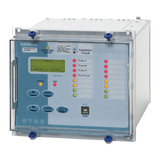
7SR242 Duobias
Multi-Function 2-Winding Transformer Protection Relay
Document Release History
This document is issue 2010/06. The list of revisions up to and including this issue is:
2010/06
Additional Comms modules option of (RS485 + IRIG-B) and (RS232 + IRIG-B) and typographical
revisions
2010/02
Document reformat due to rebrand
2010/02
Third issue. Software revision 2662H80001 R4c-3
2008/07
Second issue. Software revision 2662H80001R3d-2c.
2008/05
First issue
Software Revision History
2010/02
2662H80001 R4c-3
2008/07
2662H80001R3d-2c.
2008/05
2662H80001R3-2b
The copyright and other intellectual property rights in this document, and in any model or article produced from it
(and including any registered or unregistered design rights) are the property of Siemens Protection Devices
Limited. No part of this document shall be reproduced or modified or stored in another form, in any data retrieval
system, without the permission of Siemens Protection Devices Limited, nor shall any model or article be
reproduced from this document unless Siemens Protection Devices Limited consent.
While the information and guidance given in this document is believed to be correct, no liability shall be accepted
for any loss or damage caused by any error or omission, whether such error or omission is the result of
negligence or any other cause. Any and all such liability is disclaimed.
©2010 Siemens Protection Devices Limited
7SR242 Duobias Description Of Operation
Revisions to: VT ratio settings, 87BD 1
increments, CB fail function, LED CONFIG menu, DATA
STORAGE menu.
Added: Open circuit detection (46BC), CONTROL MODE
menu, Close circuit supervision (74CCS), Measured earth fault
undercurrent (37G), Pulsed output contacts.
Demand metering. Optional DNP3.0 data comms.
First Release
st
bias slope limit setting
Advertisement
Table of Contents

Related Manuals for Siemens 7SR242


Summary of Contents for Siemens 7SR242
- Page 1 Limited. No part of this document shall be reproduced or modified or stored in another form, in any data retrieval system, without the permission of Siemens Protection Devices Limited, nor shall any model or article be reproduced from this document unless Siemens Protection Devices Limited consent.
-
Page 2: Table Of Contents
7SR242 Duobias Description Of Operation Contents Section 1: Introduction ..........................6 Current Transformer Circuits ......................6 External Resistors..........................6 Fibre Optic Communication ......................6 Front Cover............................6 Section 2: Hardware Description ......................13 2.1 General ...........................13 2.2 Case............................13 2.3 Front Cover ..........................13 2.4 Power Supply Unit (PSU)......................14 2.5 Operator Interface/ Fascia ......................14... - Page 3 7SR242 Duobias Description Of Operation 5.4 OverFluxing Detector (81HBL5)....................46 5.5 Demand...........................47 Section 6: Other Features........................48 6.1 Data Communications......................48 6.2 Maintenance..........................48 6.2.1 Output Matrix Test......................48 6.2.2 CB Counters.......................48 6.2.3 t CB Wear ........................48 6.3 Data Storage ...........................49 6.3.1 General........................49 6.3.2 Event Records......................49 6.3.3...
- Page 4 7SR242 Duobias Description Of Operation Figure 5-2 Logic Diagram: Trip Circuit Supervision Feature (74TCS) ..........45 Figure 5-3 Logic Diagram: Close Circuit Supervision Feature (74CCS)..........45 Figure 5-4 Logic Diagram: Inrush Detector Feature (81HBL2) ............46 Figure 5-5 Logic Diagram: Overfluxing Detector Feature (81HBL5)...........46 List of Tables Table 1-1: 7SR242 Ordering Options....................7...
- Page 5 7SR242 Duobias Description Of Operation Symbols and Nomenclature The following notational and formatting conventions are used within the remainder of this document: • Setting Menu Location MAIN MENU>SUB-MENU • Setting: Elem name -Setting • Setting value: value • Alternatives: [1st] [2nd] [3rd]...
-
Page 6: Section 1: Introduction
This manual is applicable to the following relays: • 7SR242 Multi-Function 2-Winding Transformer Protection Relay The 7SR242 relay integrates the protection and control elements required to provide a complete transformer protection. The ‘Ordering Options’ Tables summarise the features available in each model. -
Page 7: Table 1-1: 7Sr242 Ordering Options
7SR242 Duobias Description Of Operation Table 1-1: 7SR242 Ordering Options □ □ □ □ □ DUOBIAS-M 7 S R 2 4 2 ▲ ▲ ▲ ▲ ▲ ▲ ▲ ▲ ▲ | | | Multifunctional 2 winding | | |... - Page 8 7SR242 Duobias Description Of Operation □ □ □ □ □ DUOBIAS-M 7 S R 2 4 2 ▲ Option C: Standard version - plus (continued from previous page) - 24 Overfluxing - 27/59 Under/overvoltage - 59N Neutral voltage displacement - 81...
-
Page 9: Figure 1-1 Functional Diagram: 7Sr242N-2Aann-0Aa0 Relay
7SR242 Duobias Description Of Operation 7SR242n-2aAnn-0AA0 W1-I BF-1 W1-I BF-1 W1-I BF-1 BF-1 87HS 87BD BF-2 (x6) (x6) W2-I BF-2 W2-I BF-2 W2-I BF-2 Figure 1-1 Functional Diagram: 7SR242n-2aAnn-0AA0 Relay ©2010 Siemens Protection Devices Limited Chapter 1 Page 9 of 52... -
Page 10: Figure 1-2 Functional Diagram: 7Sr242N-2Aann-0Ba0 Relay
7SR242 Duobias Description Of Operation 7SR242n-2aAnn-0BA0 W1-I (x2) BF-1 (x2) (x2) HBL2 HBL5 W1-I (x2) BF-1 (x2) (x2) HBL2 HBL5 W1-I (x2) BF-1 (x2) (x2) HBL2 HBL5 (x2) (x2) (x2) (x4) BF-1 (x2) (x2) (x4) Each function element can be assigned to W1 or W2 CT inputs. -
Page 11: Figure 1-3 Functional Diagram: 7Sr242N-2Aann-0Ca0 Relay
7SR242 Duobias Description Of Operation 7SR242n-2aAnn-0CA0 W1-I (x2) BF-1 (x2) (x2) HBL2 HBL5 W1-I (x2) BF-1 (x2) (x2) HBL2 HBL5 W1-I (x2) BF-1 (x2) (x2) HBL2 HBL5 (x2) (x2) (x2) (x4) BF-1 (x2) (x2) (x4) Each function element can be assigned to W1 or W2 CT inputs. -
Page 12: Figure 1-4 Connection Diagram: 7Sr242 Relay
7SR242 Duobias Description Of Operation 7SR242 BI 10 BO 7 BI 11 BO 8 Data Comms Optional CT/VT (Optional) BI 12 BO 9 BI 13 BO 10 BO 11 Rear View BI 14 BO 12 Arrangement of terminals and modules... -
Page 13: Section 2: Hardware Description
7SR242 Duobias Description Of Operation Section 2: Hardware Description General The structure of the relay is based upon the Multi-function hardware platform. The relays are supplied in either size E8 or size E10 cases (where 1 x E = width of approx. 26mm). The hardware design provides commonality between products and components across the Multi-function range of relays. -
Page 14: Power Supply Unit (Psu)
7SR242 Duobias Description Of Operation Power Supply Unit (PSU) The relay PSU can be directly connected to any substation dc system rated from 30V dc to 220V dc. In the event of the station battery voltage level falling below the relay minimum operate level the PSU will automatically switch itself off and latch out –... - Page 15 7SR242 Duobias Description Of Operation The warning and information labels on the relay fascia provide the following information: Liquid Crystal Display (LCD) A 4 line by 20-character liquid crystal display indicates settings, instrumentation, fault data and control commands. To conserve power the display backlighting is extinguished when no buttons are pressed for a user defined period.
-
Page 16: Current Inputs
7SR242 Duobias Description Of Operation initiates operation. The LED illumination colour is assigned in the OUTPUT CONFIG>LED CONFIG menu for both Pickup and Operate initiation. Functions are assigned to the LEDs in the OUTPUT CONFIG>OUTPUT MATRIX menu. Each LED can be labelled by withdrawing the relay and inserting a label strip into the pocket behind the front fascia. -
Page 17: Binary Inputs
7SR242 Duobias Description Of Operation Binary inputs The binary inputs are opto-couplers operated from a suitably rated dc supply. Relays are fitted with 9 or 19 binary inputs (BI). The user can assign any binary input to any of the available functions (INPUT CONFIG >... -
Page 18: Binary Outputs (Output Relays)
7SR242 Duobias Description Of Operation Binary outputs (Output Relays) Relays are fitted with 6 or 14 binary outputs. All outputs are fully user configurable and can be programmed to operate from any or all of the available functions. The Power Supply module includes the relay basic I/O. The module includes six binary outputs each fitted with 1 contact –... -
Page 19: Virtual Input/Outputs
7SR242 Duobias Description Of Operation Logic signals, e.g. '51-1' Reset LEDs & Outputs (TEST/RESET key, Binary Input, Data Comms) BO 1 Output 1 Event Hand Reset & & BO 1 hand reset Min Operate Time & OUTPUT CONFIG> OUTPUT MATRIX... -
Page 20: Section 3: Protection Functions
7SR242 Duobias Description Of Operation Section 3: Protection Functions Current Protection: Differential Protection Comprises both biased differential and high-set differential elements. The fundamental frequency current is measured with the line CT inputs. These line currents are both multiplied and vector corrected before being applied to the current differential elements. -
Page 21: Overall Biased Differential (87Bd)
7SR242 Duobias Description Of Operation 3.1.2 Overall Biased Differential (87BD) 2nd Bias Slope Type 87BD Initial Setting Bias (Restraint) Current Bias Slope Limit Figure 3-1 Biased Differential Characteristic Figure 3.1-1 illustrates the biased differential characteristic. Within the relay the fundamental frequency RMS line currents are modified by the ICT Multiplier and ICT Connection settings (see 3.1.1) before being applied to the... -
Page 22: Figure 3-2 Functional Diagram For Biased Current Differential Protection
7SR242 Duobias Description Of Operation 87BD Element 87BD Initial 87BD 1 Bias Slope Disabled 87BD 1 Bias Slope Limit Enabled & 87BD 2 Bias Slope Type Inhibit 87BD 87BD 2 Bias Slope 87BD ‘A’ Pickup Inhibit General Pickup W1 ICT Multiplier... -
Page 23: 87Hs
7SR242 Duobias Description Of Operation 3.1.3 87HS Figure 3-3 Differential Highset Characteristic Figure 3.1-3 illustrates the differential highset characteristic. Within the relay the fundamental frequency RMS line currents are modified by the ICT Multiplier and ICT Connection settings (see 3.1.1) before being applied to the differential highset elements. -
Page 24: Figure 3-4 Logic Diagram: High Set Current Differential Protection
7SR242 Duobias Description Of Operation 87HS Element Disabled Enabled & 87HS Setting Inhibit 87HS 87HS ‘A’ Pickup Inhibit & General Pickup trip W1 ICT Multiplier 87HS ‘B’ W1 ICT Connection Pickup Inhibit W1-IL1 trip W1-IL2 87HS Delay W1-IL3 87HS ‘C’... -
Page 25: Current Protection: Phase Overcurrent (51, 50)
7SR242 Duobias Description Of Operation Current Protection: Phase Overcurrent (51, 50) The optional phase overcurrent elements have a common setting to measure either fundamental frequency RMS or True RMS current: True RMS current: 51/50 Measurement = RMS Fundamental Frequency RMS current: 51/50 Measurement = Fundamental 3.2.1 Instantaneous Overcurrent Protection (50) -
Page 26: Time Delayed Overcurrent Protection (51)
7SR242 Duobias Description Of Operation 3.2.2 Time Delayed Overcurrent Protection (51) Optionally two time delayed overcurrent elements are provided, each can be selected to either winding 1 or winding 2. 51-n Setting sets the pick-up current level. A number of shaped characteristics are provided. An inverse definite minimum time (IDMT) characteristic is selected from IEC, ANSI or user defined curves using 51-n Char. -
Page 27: Current Protection: Derived Earth Fault (50N, 51N)
7SR242 Duobias Description Of Operation Current Protection: Derived Earth Fault (50N, 51N) The earth current is derived by calculating the sum of the measured line currents. These optional elements utilise RMS current values of the fundamental frequency (50 or 60Hz). -
Page 28: Time Delayed Derived Earth Fault Protection (51N)
7SR242 Duobias Description Of Operation 3.3.2 Time Delayed Derived Earth Fault Protection (51N) Optionally two time delayed derived earth fault elements are provided, each can be selected to either winding 1 or winding 2. 51N-n Setting sets the pick-up current level. -
Page 29: Current Protection: Measured Earth Fault (50G, 51G)
7SR242 Duobias Description Of Operation Current Protection: Measured Earth Fault (50G, 51G) The earth current is measured directly via dedicated current analogue inputs. These optional elements utilise either RMS or Fundamental current values as defined by the 51G/50G Measurement setting (MEASURED E/F menu). -
Page 30: Time Delayed Measured Earth Fault Protection (51G)
7SR242 Duobias Description Of Operation 3.4.2 Time Delayed Measured Earth Fault Protection (51G) Optionally two time delayed measured earth fault elements are provided, each can be selected to either winding 1 or winding 2. 51G-n Setting sets the pick-up current level. -
Page 31: Current Protection: High Impedance Restricted Earth Fault (64H)
7SR242 Duobias Description Of Operation Current Protection: High Impedance Restricted Earth Fault (64H) Two high impedance restricted earth fault elements are provided, one for each transformer winding The relay utilises fundamental current measurement values for this function. The single phase current input is derived from the residual output of line/neutral CTs connected in parallel. An external stabilising resistor must be connected in series with this input to ensure that this element provides a high impedance path. -
Page 32: Open Circuit (46Bc)
7SR242 Duobias Description Of Operation Open Circuit (46BC) Optionally two open circuit elements are provided, each can be selected to either winding 1 or winding 2. The element calculates the ratio of NPS to PPS currents. Where the NPS:PPS current ratio is above 46BC Setting an output is given after the 46BC Delay. -
Page 33: Current Protection: Negative Phase Sequence Overcurrent (46Nps)
7SR242 Duobias Description Of Operation Current Protection: Negative Phase Sequence Overcurrent (46NPS) Optionally four NPS current elements are provided – 2 x 46IT and 2 x 46DT. Each element can be selected to either winding 1 or winding 2. The 46IT elements can be configured to be either definite time lag (DTL) or inverse definite minimum time (IDMT), 46IT Setting sets the pick-up current level for the element. -
Page 34: Current Protection: Under-Current (37, 37G)
7SR242 Duobias Description Of Operation Current Protection: Under-Current (37, 37G) Optionally two under-current elements are provided for both line and measured earth current, each can be selected to either winding 1 or winding 2. Each phase has an independent level detector and current-timing element. 37-n Setting sets the pick-up current. -
Page 35: Current Protection: Thermal Overload (49)
7SR242 Duobias Description Of Operation Current Protection: Thermal Overload (49) Optionally a phase segregated thermal overload element is provided, this can be selected to either winding 1 or winding 2. The thermal state is calculated using the measured True RMS current. -
Page 36: Figure 3-15 Logic Diagram: Thermal Overload Protection (49)
7SR242 Duobias Description Of Operation 49 Thermal 49 Overload Setting Overload 49 Time Constant Disabled 49 Capacity Alarm Enabled & Inhibit 49 cap alarm Wn-IL1 trip 49 Alarm cap alarm Wn-IL2 trip 49 Trip cap alarm Wn-IL3 trip Figure 3-15 Logic Diagram: Thermal Overload Protection (49) ©2010 Siemens Protection Devices Limited... -
Page 37: Voltage Protection: Over Fluxing (24)
7SR242 Duobias Description Of Operation 3.10 Voltage Protection: Over Fluxing (24) Optionally, three over fluxing elements are provided – 2 x 24DT and 1 x 24IT Char elements. The 24DT Elements have a DTL characteristic. 24DT Setting sets the pick-up level and 24DT Delay the follower time delay. -
Page 38: Figure 3-17 Logic Diagram: Overfluxing Elements (24)
7SR242 Duobias Description Of Operation Figure 3-17 Logic Diagram: Overfluxing Elements (24) ©2010 Siemens Protection Devices Limited Chapter 1 Page 38 of 52... -
Page 39: Voltage Protection: Under/Over Voltage (27/59)
7SR242 Duobias Description Of Operation 3.11 Voltage Protection: Under/Over Voltage (27/59) Optionally four under/over voltage elements are provided. The relay utilises fundamental voltage measurement values for this function. 27/59-n Setting sets the pick-up voltage level for the element. The sense of the element (undervoltage or overvoltage) is set by the 27/59-n Operation setting. -
Page 40: Voltage Protection: Neutral Overvoltage (59N)
7SR242 Duobias Description Of Operation 3.12 Voltage Protection: Neutral Overvoltage (59N) Optionally two Neutral Overvoltage (or Neutral Voltage Displacement) elements are provided. One of the elements can be configured to be either definite time lag (DTL) or inverse definite minimum time... -
Page 41: Voltage Protection: Under/Over Frequency (81)
7SR242 Duobias Description Of Operation 3.13 Voltage Protection: Under/Over Frequency (81) Optionally six under/over frequency elements are provided. Frequency elements are blocked if the measured voltage falls below the 81 U/V Guard setting. The sense of the element (under-frequency or over-frequency) is set by the 81-n Operation setting. -
Page 42: Section 4: Control & Logic Functions
7SR242 Duobias Description Of Operation Section 4: Control & Logic Functions Quick Logic The ‘Quick Logic’ feature allows the user to input up to 16 logic equations (E1 to E16) in text format. Equations can be entered using Reydisp or at the relay fascia. -
Page 43: Figure 4-1 Sequence Diagram Showing Pu/Do Timers In Quick Logic (Counter Reset Mode Off)
7SR242 Duobias Description Of Operation Figure 4-1 Sequence Diagram showing PU/DO Timers in Quick Logic (Counter Reset Mode Off) When the count value = En Counter Target the output of the counter (En) = 1 and this value is held until the initiating conditions are removed when En is instantaneously reset. -
Page 44: Section 5: Supervision Functions
7SR242 Duobias Description Of Operation Section 5: Supervision Functions Circuit Breaker Failure (50BF) Two CB Fail elements are provided – one element per winding. Each circuit breaker fail function has two time delayed outputs that can be used for combinations of re-tripping or back-tripping. -
Page 45: Trip/Close Circuit Supervision (74Tcs/74Ccs)
7SR242 Duobias Description Of Operation Trip/Close Circuit Supervision (74TCS/74CCS) The relay provides six trip and six close circuit supervision elements, all elements are identical in operation and independent from each other allowing 6 trip and 6 close circuits to be monitored. -
Page 46: Inrush Detector (81Hbl2)
7SR242 Duobias Description Of Operation Inrush Detector (81HBL2) Inrush detector elements monitor the line currents. The inrush detector can be used to block the operation of selected elements during transformer magnetising inrush conditions. The 81HBL2 Bias setting allows the user to select between Phase, Sum and Cross methods of measurement: Each phase is inhibited separately. -
Page 47: Demand
7SR242 Duobias Description Of Operation Demand Maximum, minimum and mean values of line currents and voltage (where applicable) are available as instruments which can be read in the relay INSTRUMENTS MENU or via Reydisp. The DATA STORAGE > DEMAND DATA LOG > Data Log Period setting is used to define the time/duration after which the instrument is updated. -
Page 48: Section 6: Other Features
7SR242 Duobias Description Of Operation Section 6: Other Features Data Communications Two communication ports, COM1 and COM2 are provided as standard. RS485 connections are available on the terminal blocks at the rear of the relay (COM1). A USB port, COM 2, is provided at the front of the relay for local access using a PC. -
Page 49: Data Storage
7SR242 Duobias Description Of Operation the time of trip is added to the previously stored value and an alarm is given when any one of the three phase running counts exceeds the set Alarm limit . The t value is the time between CB contacts separation when an arc is formed, Separation Time, and the CB Clearance time. -
Page 50: Fault Records
7SR242 Duobias Description Of Operation In total the relay provides 10 seconds of waveform storage, this is user selectable to 1 x 10second, 2 x 5 second, 5 x 2 second or 10 x 1 second records. When the waveform recorder buffer is full any new waveform record will over-write the oldest. -
Page 51: Operating Mode
7SR242 Duobias Description Of Operation Operating Mode The relay has three operating modes, Local, Remote and Out of Service. The following table identifies the functions operation in each mode. The modes can be selected by the following methods: SYSTEM CONFIG>RELAY MODE setting, a Binary Input or Command... -
Page 52: Time Synchronisation - Data Comms
The password validation screen also displays a numerical code. If the password is lost or forgotten, this code should be communicated to Siemens Protection Devices Ltd. and the password can be retrieved. ©2010 Siemens Protection Devices Limited Chapter 1 Page 52 of 52...