Table of Contents
Advertisement
Quick Links
SERVICE MANUAL
LCD INTEGRATED DIGITAL TV
8
2005
YA299
1
PRECAUTION. . . . . . . . . . . . . . . . . . . . . . . . . . . . . . . . . . . . . . . . . . . . . . . . . . . . . . . . . . . . . . . . . . . . . . . . . 1-3
2
SPECIFIC SERVICE INSTRUCTIONS . . . . . . . . . . . . . . . . . . . . . . . . . . . . . . . . . . . . . . . . . . . . . . . . . . . . . . 1-6
3
DISASSEMBLY . . . . . . . . . . . . . . . . . . . . . . . . . . . . . . . . . . . . . . . . . . . . . . . . . . . . . . . . . . . . . . . . . . . . . . 1-11
4
ADJUSTMENT . . . . . . . . . . . . . . . . . . . . . . . . . . . . . . . . . . . . . . . . . . . . . . . . . . . . . . . . . . . . . . . . . . . . . . . 1-18
5
TROUBLESHOOTING . . . . . . . . . . . . . . . . . . . . . . . . . . . . . . . . . . . . . . . . . . . . . . . . . . . . . . . . . . . . . . . . . 1-25
LT-37DS6FJ
TABLE OF CONTENTS
COPYRIGHT © 2005 Victor Company of Japan, Limited
/P
BASIC CHASSIS
FL2
2005/8
Advertisement
Chapters
Table of Contents
Troubleshooting

Related Manuals for JVC LT-37DS6FJ/p


Summary of Contents for JVC LT-37DS6FJ/p
-
Page 1: Table Of Contents
SERVICE MANUAL LCD INTEGRATED DIGITAL TV YA299 2005 LT-37DS6FJ BASIC CHASSIS TABLE OF CONTENTS PRECAUTION............... . . 1-3 SPECIFIC SERVICE INSTRUCTIONS . - Page 2 SPECIFICATION Items Contents Dimensions ( W × H × D ) 92.6 cm × 113.0 cm × 56.5 cm [Included stand] 92.6 cm × 63.1 cm × 10.8 cm [TV only] Mass 39.4 kg [Included stand] 20.9 kg [TV only] Power Input AC110V - AC240 V, 50 Hz / 60 Hz Power Consumption...
-
Page 3: Precaution
SECTION 1 PRECAUTION SAFETY PRECAUTIONS (1) The design of this product contains special hardware and many circuits and components specially for safety purposes. For continued protection, no changes should be made to the original design unless authorized in writing by the manufacturer. Replacement parts must be identical to those used in the original circuits. - Page 4 INSTALLATION 1.2.1 HEAT DISSIPATION 1.2.3 INSTALLATION REQUIREMENTS If the heat dissipation vent behind this unit is blocked, cooling To ensure safety in an emergency such as an earthquake, and efficiency may deteriorate and temperature inside the unit will to prevent accidents, ensure that measures are taken to prevent rise.
- Page 5 HANDLING LCD PANEL 1.3.1 PRECAUTIONS FOR TRANSPORTATION 1.3.2 OPTICAL FILTER (ON THE FRONT OF THE LCD PANEL) When transporting the unit, pressure exerted on the internal LCD (1) Avoid placing the unit under direct sunlight over a panel due to improper handling (such as tossing and dropping) prolonged period of time.
-
Page 6: Specific Service Instructions
SECTION 2 SPECIFIC SERVICE INSTRUCTIONS SYSTEM SETTEING Be sure to carry out the following operation at the end of MAIN MENU SCREEN the procedure. SERVICE MENU SERVICE MENU (1) Press the [INFORMATION] key and [MUTING] key 1.ADJUST 1.ADJUST 2.SELF_CHK 2.SELF_CHK simultaneously, then enter the SERVICE MODE. - Page 7 21-PIN EURO CONNECTOR (SCART) : EXT-1 / EXT-2 Pin No. Signal designation Matching value EXT-1 EXT-2 AUDIO R output 500mV(rms) (Nominal), Low impedance Used (TV OUT) Used (LINE OUT) AUDIO R input 500mV(rms) (Nominal), High impedance Used (R1) Used (R2) AUDIO L output 500mV(rms) (Nominal), Low impedance Used (TV OUT)
- Page 8 TECHNICAL INFORMATION 2.4.1 LCD PANEL This unit uses the flat type panel LCD (Liquid Crystal Display) panel that occupies as little space as possible, instead of the conventional CRT (Cathode Ray Tube), as a display unit. Since the unit has the two polarizing filter that are at right angles to each other, the unit adopts "normally black" mode, where light does not pass through the polarizing filter and the screen is black when no voltage is applied to the liquid crystals.
- Page 9 2.4.2 MAIN CPU PIN FUNCTION [IC7501 : DIGITAL SIGNAL PWB] Pin name Function Pin name Function Test purpose I/O Program ROM data for main CPU Test purpose I/O Program ROM data for main CPU Test purpose I/O Program ROM data for main CPU Test purpose VSS33 P2.8...
- Page 10 2.4.3 SUB (CHASSIS) CPU PIN FUNCTION [IC7001 : DIGITAL SIGNAL PWB] Pin name Function Pin name Function LB_PRO Not used BS_TXD Data transmission for digital tuner communication P_MU Picture muting [Muting = H] BS_RXD Data receive for digital tuner communication JP_CSB Not used (NC) Not used (NC)
-
Page 11: Disassembly
SECTION 3 DISASSEMBLY DISASSEMBLY PROCEDURE CAUTION AT DISASSEMBLY: • Be sure to perform the SYSTEM SETTEING, at the end of the procedure. • Make sure that the power cord is disconnected from the outlet. • Pay special attention not to break or damage the parts. •... - Page 12 JACK COVER STAND COVER JACK COVER STAND TUNER BASE REAR COVER FAN BRACKET SHIELD COVER REGULATOR PWB RECEIVER PWB POWER PWB DIGITAL TUNER UNIT POWER CORD RECEIVER PWB BRACKET SIDE SHIELD CASE POWER CORD HOLDER TOP SHIELD CASE ANALOG SIGNAL PWB DIGITAL BRACKET CONNECTOR DIGITAL SIGNAL PWB...
- Page 13 3.1.11 REMOVING THE SPEAKER (Fig.2) • Remove the STAND. • Remove the REAR COVER. (1) Remove the 6 screws [A], then remove the SPEAKER (L /R). NOTE: • Since the speaker is attached in a certain direction, attach the speaker in the same correct direction as it has been attached.
- Page 14 MAIN BASE BOTTOM FRAME TOP FRAME SPEAKER FRONT LED PWB SPEAKER LED LENS FRONT PANEL FRONT Fig.2 1-14 (No.YA299)
- Page 15 MEMORY IC REPLACEMENT • This model uses the memory IC. • This memory IC stores data for proper operation of the video and drive circuits. • When replacing, be sure to use an IC containing this (initial value) data. 3.2.1 MEMORY IC REPLACEMENT PROCEDURE 1.
- Page 16 3.2.3 SETTINGS OF FACTORY SHIPMENT 3.2.3.1 BUTTON OPERATION 3.2.3.2 REMOTE CONTROL DIRECT OPERATION Setting item Setting position Setting item Setting position POWER CHANNEL CHANNEL VOLUME VOLUME ZOOM PANORAMIC TV/AV 3D SOUND 3.2.3.3 REMOTE CONTROL MENU OPERATION (1) PICTURE (4) FEATURES Setting item Setting position Setting item...
- Page 17 REPLACEMENT OF CHIP COMPONENT 3.3.1 CAUTIONS (1) Avoid heating for more than 3 seconds. (2) Do not rub the electrodes and the resist parts of the pattern. (3) When removing a chip part, melt the solder adequately. (4) Do not reuse a chip part after removing it. 3.3.2 SOLDERING IRON (1) Use a high insulation soldering iron with a thin pointed end of it.
-
Page 18: Adjustment
SECTION 4 ADJUSTMENT ADJUSTMENT PREPARATION ADJUSTMENT ITEMS (1) The adjustment using the REMOTE CONTROL UNIT is VIDEO CIRCUIT made on the basis of the initial setting values. The set- • 625i A-D OFFSET adjustment ting values which adjust the screen to the optimum •... - Page 19 4.5.3 DESCRIPTION OF STATUS DISPLAY (5) SETTING ITEM NAME Setting item name are displayed. The setting item numbers to SETTINGITEM No. SETTING ITEM SETTING VALUE (DATA) be displayed are listed below. Item No. Setting item S001 to S039 Video system setting S001 PREPARE S001 PREPARE PAL50...
- Page 20 INITIAL SETTING VALUES IN THE SERVICE MODE • Perform fine-tuning based on the "initial values" using the remote control when in the Service mode. • The "initial values" serve only as an indication rough standard and therefore the values with which optimal display can be achieved may be different from the default values.
- Page 21 Item No. Item name Variable range Setting value Item No. Item name Variable range Setting value D020 SYH CON 00 - 3F D070 (Not display) 00 - FF D021 SYH CONF 00 - 01 D071 (Not display) 00 - FF D022 SC CON 00 - 3F...
- Page 22 Item No. Item name Variable range Setting value Item No. Item name Variable range Setting value D120 (Not display) 00 - FF D170 (Not display) 00 - FF D121 (Not display) 00 - FF D171 (Not display) 00 - FF D122 (Not display) 00 - FF...
- Page 23 ADJUSTMENT PROCEDURE 4.7.1 VIDEO CIRCUIT Measuring Item Test point Adjustment part Description instrument 625i Remote [1.ADJUST] (1) Receive a 625i component ramp pattern signal. A-D OFFSET control unit S001: PREPARE (2) Set PICTURE MODE to "STANDARD". (Adjustment setting mode change) (3) Set ZOOM to "FULL".
- Page 24 Measuring Item Test point Adjustment part Description instrument SUB SCREEN Remote [1.ADJUST] (1) Set PICTURE MODE to "STANDARD". A-D OFFSET control unit S001: PREPARE (2) Set ZOOM" to "FULL". (Adjustment setting mode change) (3) Set COLOUR TEMP. to "NORMAL". Signal (4) Set MULTI SCREEN to "2 pictures".
-
Page 25: Troubleshooting
SECTION 5 TROUBLESHOOTING SELF CHECK FEATURE 5.1.5 POINTS TO NOTE WHEN USING THE SELF CHECK FEATURE 5.1.1 OUTLINE In addition to circuit failures (abnormal operation), the following This unit comes with the "Self check" feature, which checks the cases may also be iagnosed as "Abnormal" and displayed and operational state of the circuit and displays/saves it during counted as "NG". -
Page 26: No.ya299
5.1.6 DETAILS Self check is performed for the following items: < Page 1 of screen > Diagnosis Detection item Display Detection content Detection timing signal (line) Low bias line short Confirmation of operation of the low bais LB_PRO Detection starts 3 seconds after the protection (2.5V / 3.3V / 5V / 9V) protection circuit. - Page 27 < Page 2 of screen > Diagnosis Detection item Display Detection content Detection timing signal (line) Fan lock Not used. Abnormal of operation of Not used. PANEL Abnormal rise of Not used. temperature in PANEL Abnormal rise of Not used. temperature in audio circuit Short circuit detection of...
- Page 28 Victor Company of Japan, Limited AV & MULTIMEDIA COMPANY DISPLAY CATEGORY 12, 3-chome, Moriya-cho, Kanagawa-ku, Yokohama-city, Kanagawa-prefecture, 221-8528, Japan (No.YA299) Printed in Japan...
-
Page 29: Parts List
PARTS LIST CAUTION The parts identified by the symbol are important for the safety . Whenever replacing these parts, be sure to use specified ones to secure the safety. The parts not indicated in this Parts List and those which are filled with lines --- in the Parts No. columns will not be supplied. P.W. - Page 30 CONTENTS USING P.W. BOARD & REMOTE CONTROL UNIT ....................3-2 EXPLODED VIEW PARTS LIST -1 ..........................3-3 EXPLODED VIEW -1 ..............................3-4 EXPLODED VIEW PARTS LIST -2 ..........................3-5 EXPLODED VIEW -2 ..............................3-6 PRINTED WIRING BOARD PARTS LIST ........................3-7 ANALOG SIGNAL P.W.
-
Page 31: Exploded View Parts List -1
EXPLODED VIEW PARTS LIST -1 Ref.No. Part No. Part Name Description Local LC21923-001A-U JACK COVER (x2) LC21990-002A-U RATING LABEL LC32749-005A-H OPERATION SHEET GA10137-001A-U STAND ASSY 104A GA20108-001A-U STAND COVER 104B GA10145-001A-U GLASS SHELF 104C GA10144-001A-U GLASS BASE QYSPSPD5014MA SCREW M5 x 14mm(x4) LC12450-001A-U REAR COVER... -
Page 32: Exploded View -1
EXPLODED VIEW -1 104A 104B 104C FAN BRACKET SHIELD COVER RECEIVER PWB BRACKET SIDE SHIELD CASE TOP SHIELD CASE DIGITAL BRACKET 3-4(No.YA299) -
Page 33: Exploded View Parts List -2
EXPLODED VIEW PARTS LIST -2 Ref.No. Part No. Part Name Description Local 150 QLD0375-001-JUK LCD PANEL UNIT WJW0021-002A-E DIGITAL(LVDS) CABLE QQR0490-001 NOISE FILTER LC41913-004A-C SPEAKER ASSY LC40226-005A-H SPACER (x6) LC41913-003A-C SPEAKER ASSY LC12449-001A-U FRONT PANEL ASSY QQR0490-001 NOISE FILTER LC33125-001B-HK LED LENS ... -
Page 34: Exploded View -2
EXPLODED VIEW -2 MAIN BASE BOTTOM FRAME TOP FRAME FRONT 3-6(No.YA299) -
Page 35: Printed Wiring Board Parts List
PRINTED WIRING BOARD PARTS LIST ANALOG SIGNAL P.W. BOARD ASS'Y (SFL-1113A-U2) Ref No. Part No. Part Name Description Local Ref No. Part No. Part Name Description Local D901 NRSA02J-0R0X MG RESISTOR 0Ω 1/10W J D902 1SS355-X SI DIODE IC201 TB1305FG D903 PTZ11B-X Z DIODE... - Page 36 Ref No. Part No. Part Name Description Local Ref No. Part No. Part Name Description Local C313 NCB31HK-103X C CAPACITOR 0.01uF 50V K C852 NDC31HJ-560X C CAPACITOR 56pF 50V J C314 NCB31HK-103X C CAPACITOR 0.01uF 50V K C853 NEHL1CM-476X E CAPACITOR 47uF 16V M C315 NCB31HK-103X...
- Page 37 Ref No. Part No. Part Name Description Local Ref No. Part No. Part Name Description Local C2402 NCB31HK-103X C CAPACITOR 0.01uF 50V K C6664 QETN1HM-226Z E CAPACITOR 22uF 50V M C2451 NCB11CK-225X C CAPACITOR 2.2uF 16V K C6665 NCB31HK-104X C CAPACITOR 0.1uF 50V K C2452 NCB11CK-225X...
- Page 38 Ref No. Part No. Part Name Description Local Ref No. Part No. Part Name Description Local R540 NRSA63J-183X MG RESISTOR 18kΩ 1/16W J R853 NRSA63J-183X MG RESISTOR 18kΩ 1/16W J R541 NRSA63J-0R0X MG RESISTOR 0Ω 1/16W J R854 NRSA63J-822X MG RESISTOR 8.2kΩ...
-
Page 39: Connector P.w. Board Ass'y (Sfl-4111A-U2)
Ref No. Part No. Part Name Description Local Ref No. Part No. Part Name Description Local R2603 NRSA63J-750X MG RESISTOR 75Ω 1/16W J R6623 NRSA63J-392X MG RESISTOR 3.9kΩ 1/16W J R2604 NRSA63J-331X MG RESISTOR 330Ω 1/16W J R6624 QRJ146J-102X UNF C RESISTOR 1kΩ... -
Page 40: Front Control P.w. Board Ass'y (Sfl-7111A-U2)
Ref No. Part No. Part Name Description Local Ref No. Part No. Part Name Description Local D4904 MA111-X SI DIODE R7013 NRSA63J-101X MG RESISTOR 100Ω 1/16W J R7014 NRSA63J-101X MG RESISTOR 100Ω 1/16W J C4210 QETN0JM-228Z E CAPACITOR 2200uF 6.3V M R7015 NRSA63J-103X MG RESISTOR... - Page 41 Ref No. Part No. Part Name Description Local Ref No. Part No. Part Name Description Local D9021 MA111-X SI DIODE C9553 QEHR1EM-477Z E CAPACITOR 470uF 25V M D9111 S1WB/A/60-4101 BRIDGE DIODE C9606 NCB11CK-475X C CAPACITOR 4.7uF 16V K D9201 D25XB60 BRIDGE DIODE C9608 QEHR1EM-107Z...
-
Page 42: Regulator P.w. Board Ass'y (Sfl-9133A-U2)
REGULATOR P.W. BOARD ASS'Y (SFL-9133A-U2) Ref No. Part No. Part Name Description Local Ref No. Part No. Part Name Description Local R9546 NRSA63J-182X MG RESISTOR 1.8kΩ 1/16W J R9548 NRSA63D-392X MG RESISTOR 3.9kΩ 1/16W D IC9801 MP1593DN-X R9549 NRSA63J-0R0X MG RESISTOR 0Ω... -
Page 43: Digital Signal P.w. Board Ass'y (Lca10557-70A) (Sfl-0D237A)
Ref No. Part No. Part Name Description Local Ref No. Part No. Part Name Description Local R9864 NRSA63J-680X MG RESISTOR 68Ω 1/16W J Q0310 HN1C01F/Y/-X PAIR TRANSISTOR R9865 NRSA63J-103X MG RESISTOR 10kΩ 1/16W J Q0311 2SC3928A/QR/-X TRANSISTOR R9866 NRSA63D-153X MG RESISTOR 15kΩ... - Page 44 Ref No. Part No. Part Name Description Local Ref No. Part No. Part Name Description Local C0401 NCB31CK-104X C CAPACITOR 0.1uF 16V K C1405 NCF11CZ-475X C CAPACITOR 4.7uF 16V Z C0519 NDC31HJ-560X C CAPACITOR 56pF 50V J C1406 NCB31CK-104X C CAPACITOR 0.1uF 16V K C1001 NCB31HK-103X...
- Page 45 Ref No. Part No. Part Name Description Local Ref No. Part No. Part Name Description Local C4003 NCB31CK-104X C CAPACITOR 0.1uF 16V K C7517 NDC31HJ-270X C CAPACITOR 27pF 50V J C4005 NCB31AK-105X C CAPACITOR 1uF 10V K C7518 NRSA63J-0R0X MG RESISTOR 0Ω...
- Page 46 Ref No. Part No. Part Name Description Local Ref No. Part No. Part Name Description Local R0242 NRSA63J-472X MG RESISTOR 4.7kΩ 1/16W J R1306 NRSA63J-471X MG RESISTOR 470Ω 1/16W J R0243 NRSA63J-103X MG RESISTOR 10kΩ 1/16W J R1307 NRSA63J-561X MG RESISTOR 560Ω...
- Page 47 Ref No. Part No. Part Name Description Local Ref No. Part No. Part Name Description Local R3165 NRSA63J-0R0X MG RESISTOR 0Ω 1/16W J R6532 NRSA63J-102X MG RESISTOR 1kΩ 1/16W J R3166 NRSA63J-0R0X MG RESISTOR 0Ω 1/16W J R6533 NRSA63J-0R0X MG RESISTOR 0Ω...
- Page 48 Ref No. Part No. Part Name Description Local Ref No. Part No. Part Name Description Local R7144 NCB30JK-105X C CAPACITOR 1uF 6.3V K R9206 NRSA63J-472X MG RESISTOR 4.7kΩ 1/16W J R7145 NCB30JK-105X C CAPACITOR 1uF 6.3V K R9207 NRSA02J-0R0X MG RESISTOR 0Ω...
-
Page 49: Receiver P.w. Board Ass'y (Sfl0F203A-U2)
Ref No. Part No. Part Name Description Local Ref No. Part No. Part Name Description Local L3011 NRSA02J-0R0X MG RESISTOR 0Ω 1/10W J C3008 NCB31HK-103X C CAPACITOR 0.01uF 50V K L3012 NRSA02J-0R0X MG RESISTOR 0Ω 1/10W J C3009 NEHL1HM-106X E CAPACITOR 10uF 50V M L3013 NQL093K-R10X... -
Page 50: Remote Control Unit Parts List (Rm-C1813H-1C)
Ref No. Part No. Part Name Description Local Ref No. Part No. Part Name Description Local R3516 NRSA63J-101X MG RESISTOR 100Ω 1/16W J R3576 NRSA63J-101X MG RESISTOR 100Ω 1/16W J R3517 NRSA63J-103X MG RESISTOR 10kΩ 1/16W J R3577 NRSA63J-101X MG RESISTOR 100Ω... -
Page 51: Packing
PACKING Please refer to RK-C37FS1 service manual (No.YA341). PACKING PARTS LIST Ref.No. Part No. Part Name Description Local GA10002-071A-U PACKING CASE (For SET) GA10027-026A-U EURO LABEL GA10133-001A-U CUSHION ASSY 4pcs in 1set (For SET) GA10026-003A-U FORM BAG RM-C1813H-1C REMOCON UNIT GA30007-001A-U DOCUMENT BAGS ... - Page 52 SCHEMATIC DIAGRAMS LCD INTEGRATED DIGITAL TV YA299 2005 LT-37DS6FJ BASIC CHASSIS CD-ROM No.SML200508 No.YA299 COPYRIGHT © 2005 Victor Company of Japan, Limited 2005/8...
-
Page 53: Standard Circuit Diagram
LT-37DS6FJ STANDARD CIRCUIT DIAGRAM NOTE ON USING CIRCUIT DIAGRAMS 1.SAFETY Type The components identified by the symbol and shading are No indication : Ceramic capacitor critical for safety. For continued safety replace safety ciritical : Metalized mylar capacitor : Polypropylene capacitor components only with manufactures recommended parts. - Page 54 REGULATOR PWB PATTERN ........................2-67 FRONT CONTROL PWB PATTERN ......................2-69 FRONT LED PWB PATTERN ........................2-69 VOLTAGE CHATRS................... 2-71 WAVEFORMS .................... 2-74 USING P.W. BOARD P.W.B ASS’Y name LT-37DS6FJ/P ANALOG SIGNAL P.W. BOARD SFL-1113A-U2 CONNECTOR P.W. BOARD SFL-4111A-U2 FRONT CONTROL P.W. BOARD SFL-7111A-U2 SFL-8113A-U2 FRONT LED P.W.
-
Page 55: Wiring Diagram
WIRING DIAGRAM CONNECTOR PWB CN1011 TU3001 ANALOG TUNER ANALOG SIGNAL PWB CN1012 CN011 RECEIVER PWB CN0002 CN0001 CN012 LCD PANEL UNIT CN003 CN002 CN001 CN0ID CN000W CN003 CN0LV2 CN0006 CN0007 CN9806 DIGITAL SIGNAL PWB F9001 POWER PWB 250V/6.3A CN9807 PL107 PL207 PL200 POWER CORD... -
Page 56: Block Diagram
BLOCK DIAGRAM FRONT CONTROL PWB IC3501 ANALOG SIGNAL PWB RECEIVER PWB IC6521 IC3503 MULTI SOUND PROCESS SPEAKER(L) BBE/SURROUND/AUDIO CONTROL HEADPHONE IC6621 J7001 LIPL LIPL IC6001 IC6661 COMPARAT TU3002 LIPR LIPR SIF_OUT BASS VOLUME SURROUND IC6551 DEMOD. IC6552 DIGITAL SPLIT U/V FRONTEND VOL1 TONE VOL2... -
Page 57: Circuit Diagrams
CIRCUIT DIAGRAMS RECEIVER PWB CIRCUIT DIAGRAM SHEET 1 SFL- SFL- SFP- 0F203A 0F204A 0F205A OLLC08303 OLLC08303 OLLC08116 RECEIVER PWB ASS'Y QGA2001C6 CNF00A OPEN OPEN -03X QGA2001F6 QGA2001F6 SFL0F203A-U2 CNF01A OPEN -03X -03X QAU0428 TU3001 OPEN OPEN -001 QAU0428 QAU0428 TU3002 OPEN -001 -001... -
Page 58: Analog Signal Pwb Circuit Diagram
ANALOG SIGNAL PWB CIRCUIT DIAGRAM (1/5) SHEET 2 DIGITAL TUNER DIGITAL TUNER UNIT SHEET4 SHEET3 UNIT CN00UA J2007 CN00UV QNZ0561-001 PC_HS PC_VS C511 C512 OPEN OPEN C2601 PC_DET C513 C514 PC_R C591 C592 C593 C594 C595 R596 C2602 PC_G R597 C_DIG C2603 PC IN... - Page 59 ANALOG SIGNAL PWB CIRCUIT DIAGRAM (2/5) SHEET 3 FRONT LED PWB ASSS'Y CN100U (SHEET20) SHEET4 SHEET5 CN000U SHEET4 SHEET2 GQA1501C5-09W SHEET2 SHEET4 SHEET2 STB_5V BS_A3V BS_A5V CN0011 CN0011 CN0012 QGF0508F1-50X QGF0508F1-50X SSM3K17FU-X R402 BS_A9V QGF0508F1-50X Q402 SCL3B BS_A5V LIP_R SDA3B BS_A9V TEXT_FB1 R406...
- Page 60 ANALOG SIGNAL PWB CIRCUIT DIAGRAM (3/5) SHEET 4 PC_VS SHEET2 PC_HS Y204 Y203 NRSA02J-0R0X NOTE Y202 NRSA02J-0R0X NPN: 2SC3928A/GR/-X PNP: 2SA1530A/QR/-X Y201 This sheet difference list. R336 5.6k C349 YUVSWY1 R219 SYNC1_IN R220 R334 2.2k Q307 C223 R335 2.2k C338 OPEN R208 C211...
- Page 61 ANALOG SIGNAL PWB CIRCUIT DIAGRAM (4/5) SHEET 5 IC6201 ANALOG SIGNAL PWB ASS'Y (4/5) PQ20WZ11-X SFL-1113A-U2 AU_+VCC VCC12V Y6202 Y6201 D6201 1SS355-X C6204 C6621 R6201 R6621 R6622 R6203 3300p 5.6K AU_+VCC R6624 C6202 C6201 R6205 C6205 R6623 0.01 0.01 QRJ146J-102X 3.9k R6625 Q6523...
- Page 62 ANALOG SIGNAL PWB CIRCUIT DIAGRAM (5/5) SHEET 6 RECEIVER PWB ASS'Y CNF01A (SHEET1) CN000A QGA2001C2-03V Y909 OPEN Y910 OPEN Y921 OPEN DIFFERENCE LIST Y922 OPEN GND_S5 GND2 26/32DS6 26/32S60 37DS6 37S60 ASS'Y LCA90494 LCA90494 LCA90494 LCA90494 -04* -01* -02* -03* SFL-1111A SFL-1112A SFL-1113A...
-
Page 63: Digital Signal Pwb Circuit Diagram
DIGITAL SIGNAL PWB CIRCUIT DIAGRAM (1/11) SHEET 7 BS_9V L1531 OPEN L1532 OPEN C1531 C1532 OPEN OPEN R1540 R1541 R1532 OPEN OPEN OPEN Q1531 MAIN_VY OPEN C1533 SHEET17 OPEN Q1532 R1535 YUVSW_Y1 OPEN OPEN R1551 OPEN C1536 R1536 OPEN Q1534 OPEN OPEN RA1532... - Page 64 DIGITAL SIGNAL PWB CIRCUIT DIAGRAM (2/11) SHEET 8 L0104 OPEN R0131 4.7k L0204 C0115 C0116 OPEN R0132 0.1/16 10/10 C0110 4.7k R0133 L0304 OPEN Q0109 C0119 HN1C01F/Y/-X OPEN BS_9V C0111 AGND DGND R0101 AGND OPEN R0136 OPEN C0112 LC0102 EFP5 NQR0483-005X R0138 CmpAY...
- Page 65 DIGITAL SIGNAL PWB CIRCUIT DIAGRAM (3/11) SHEET 9 - NOTE - 0 : NRSA63J-0R0X NPN : 2SC3928A/QR/-X VCC3D PNP : 2SA1530A/QR/-X NRZ : NRZ0040-0R0X L1010 NRSA02J-0R0X CORE2 : NQR0489-002X L1R5 : NQL092K-1R5X IC1002 MM1572FN-X D1001 L2R2 : NQL092K-2R2X EC30HA03L-X L1011 C1065 D1002 C1076...
- Page 66 DIGITAL SIGNAL PWB CIRCUIT DIAGRAM (4/11) SHEET 10 SHEET16 VFORMSel SYNCSEL RB2004 RB2004 OPEN OPEN RB2005 RB2005 OPEN OPEN RB2006 RB2006 OPEN OPEN PLDR_UV7 PLDR_UV7 PLDR_UV6 PLDR_UV6 PLDR_UV5 PLDR_UV5 SHEET11 PLDR_UV4 PLDR_UV4 RB2001 RB2001 OPEN OPEN PLDR_UV3 PLDR_UV3 PLDR_UV2 PLDR_UV2 PLDR_UV1 PLDR_UV1 PLDR_UV0...
- Page 67 DIGITAL SIGNAL PWB CIRCUIT DIAGRAM (5/11) SHEET 11 SD_DQS0 SD_DQS1 RA3516 RA3540 RA3542 RA3518 C3506 2.2/6.3 C3507 C3530 C3532 0.47/16 2.2/6.3 C3125 C3124 OPEN DIGITAL SIGNAL PWB ASS'Y (5/11) DQ28 DQ28 C3508 C3531 C3533 0.47/16 VDDQ VDDQ C3509 VDDQ VDDQ 2.2/6.3 2.2/6.3 DQ27...
- Page 68 DIGITAL SIGNAL PWB CIRCUIT DIAGRAM (6/11) SHEET 12 # DIFFRENCE LIST - NOTE - NOTE 32,26 32,26 32,26 0 : NRSA63J-0R0X Selling ASIA VCC3D Country ASSY SFL-0D232A SFL-0D237A SFL-0D235A SFL-0D238A SFL-0D332A SFL-0D233A SFL-0D236A SFL-0D333A RA4016 RA4016 OLLC07697 OLLC07697 OLLC07697 OLLC07697 OLLC07697 OPEN OPEN...
- Page 69 DIGITAL SIGNAL PWB CIRCUIT DIAGRAM (7/11) SHEET 13 LV_HS TUNNER SEPARATE TYPE : NO MOUNT IN LVDS OUT BLOCK SHEET12 # DIFFRENCE LIST LV_VS LV_BLK NOTE 32,26 32,26 32,26 Selling ASIA PL_SDA Country PL_SCL ASSY SHEET14 SFL-0D232A SFL-0D237A SFL-0D235A SFL-0D238A SFL-0D332A SFL-0D233A SFL-0D236A...
- Page 70 DIGITAL SIGNAL PWB CIRCUIT DIAGRAM (8/11) SHEET 14 CN0FC OPEN K6001 OPEN DIGITAL SIGNAL PWB ASS'Y (8/11) AUDIO_R- K6002 OPEN AUDIO_R+ K6003 OPEN AUDIO_L- LCA10557-70A (SFL-0D237A) K6004 OPEN AUDIO_L+ K6005 OPEN MECA K6006 OPEN KEY1 K6007 OPEN KEY2 K6008 OPEN REMCON K6021 OPEN...
- Page 71 DIGITAL SIGNAL PWB CIRCUIT DIAGRAM (9/11) SHEET 15 DIGITAL SIGNAL PWB ASS'Y (9/11) NOTE : Refer to the part list for the part number of IC7602. LCA10557-70A (SFL-0D237A) SHEET16,17 WAKE SHEET11 OSDB5 CARD_DET OSDB5 SHEET10,12,17 STB3.3V OSDB4 OSDB4 R7681 OPEN DD_OSDVS OSDB3 IC7602...
- Page 72 DIGITAL SIGNAL PWB CIRCUIT DIAGRAM (10/11) SHEET 16 DIGITAL INPUT BLOCK # DIFFRENCE LIST NOTE 32,26 32,26 32,26 Selling ASIA STB3.3V Country ASSY DIGITAL SIGNAL PWB ASS'Y (10/11) SFL-0D232A SFL-0D237A SFL-0D235A SFL-0D238A SFL-0D332A SFL-0D233A SFL-0D236A SFL-0D333A SN74LVC2G241T-X OLLC07697 OLLC07697 OLLC07697 OLLC07697 OLLC07697 ( etc)
- Page 73 DIGITAL SIGNAL PWB CIRCUIT DIAGRAM (11/11) SHEET 17 DIGITAL TUNER UNIT SHEET12 SHEET10 OPEN # DIFFRENCE LIST CN0ID CN0MI C7554 C7555 QGA1501F2-07V STB3.3V VCC1.5D TVLINKOUT SHEET16 C4919 C4958 C4960 C4962 C4964 C4921 C4936 C4913 C4916 C4955 DGND 0.01 OPEN OPEN OPEN OPEN 0.01...
-
Page 74: Connector Pwb Circuit Diagram
CONNECTOR PWB CIRCUIT DIAGRAM SHEET 18 TO DIGITAL PB CN0001 CN0001 QGF0508F1-50X CN1011 CN1011 QGF0508F1-50X QGF0508C1-50W SCL3B SCL3B SDA3B SDA3B LCA90495-01* TEXT_FB1 MOUNTING TEXT_FB1 TEXT_FB1 SFL-4111A TEXT_FG1 TEXT_FG1 TEXT_FG1 LCA90495-02* TEXT_FR1 TEXT_FR1 TEXT_FR1 OPEN REC_RSV SFL-4112A ANALOG SIGNAL SUB_CCD SUB_CCD DIN_PHOTO PWB ASS'Y(5/5) SCL_3A... -
Page 75: Front Control Pwb Circuit Diagram
FRONT CONTROL PWB CIRCUIT DIAGRAM SHEET 19 FRONT LED PWB CIRCUIT DIAGRAM SHEET 20 R8714 R8716 R8715 R8713 R8712 R8717 R8711 CN100U QGA1501C5-09W POWER_LED Q8708 Q8707 CN100R QGA1501C5-10W DIMMED_LED R8725 STB5V KEY1 S7707 C7701 QSW1131-001Z FUNC D8712 Q8704 Q8702 KEY2 Q8701 OPEN REC_LED... - Page 76 POWER PWB CIRCUIT DIAGRAM (1/2) SHEET 21 POWER PWB ASS'Y (1/2) SFL-9033A-U2 OPEN CN000D QGA7901C1-02 Y9013 OPEN C9002 Y9014 QFZ9072-105 F9001 OPEN QMF5AD2-6R3-J1 R9001 R9202 QRZ9046-105Z OPEN CN00PW LF9001 LF9002 LF9003 QQR1514-001 QQR1514-001 QGA7901C1-02 POWER VA9001 R9201 QAF0060-621 QRZ9055-8R2 L9201 CORD H9211 LC32819-001B...
- Page 77 POWER PWB CIRCUIT DIAGRAM (2/2) SHEET 22 OPEN LCD PANEL UNIT CN000Q CN000P QGA2001C6-10X CN0CV3 OPEN K9505 NQR0499-002X OPEN GND5 Q9608 CN000Y GND6 GND4 OPEN OPEN OLLC08326 OLLC08326-02 OLLC08494 OLLC08494-02 D9301 OPEN CP9301 FME-220A R9604 C9608 QEHR1EM-107Z QEHR1EM-107Z OPEN OPEN QMFZ034-5R0Z-J1 OPEN C9910...
- Page 78 REGULATOR PWB CIRCUIT DIAGRAM SHEET 23 D9801 OPEN R9801 C9807 OPEN 0.0033 R9802 NCB31HK-332X C9801 OPEN OPEN R9804 5.6k R9810 GND2 GND2 C9802 C9805 OPEN 0.0022 NCB31HK-222X GND2 GND2 Q9801 L9802 R9803 IC9801 2SC3928A/QR/-X D9805 NQL98EM-150X MP1593DN-X PTZ6.8B-X D9803 MA111-X L9801 R9812 D9802...
-
Page 79: Pattern Diagrams
PATTERN DIAGRAMS RECEIVER PWB PATTERN [SOLDER SIDE] RECEIVER PWB PATTERN [PARTS SIDE] R3043 R3014 R3015 C3574 IC3506 IC3507 R3573 R3582 R3578 R3040 IC3510 C3113 R3574 R3039 R3583 IC3508 IC3104 C3571 R3516 C3114 R3575 R3584 R3038 R3579 IC3509 R3577 R3585 C3115 R3576 D3104 R3037... -
Page 80: Analog Signal Pwb Pattern
ANALOG SIGNAL PWB PATTERN [SOLDER SIDE] R2058 R2057 C2053 R2056 R2171 J2003 J2005 R2054 R2172 C2052 R2055 J2007 R2053 R2052 R2051 J2001 J2002 R2603 J2004 R2606 C2452 R2602 R2454 D2606 D2603 D2601 R2455 R2456 D2602 Q2453 Q2452 C2453 R2457 R2458 C6545 R6534 C2451... - Page 81 ANALOG SIGNAL PWB PATTERN [PARTS SIDE] J2004 D2204 J2002 J2001 J2007 J2003 C2206 R2201 R2101 D2001 C2153 C2201 C2109 C2108 C2107 D2105 D2106 D2103 D2102 R2106 R2151 C2011 C2010 C2009 C2008 D2004 D2107 D2005 D2002 D2003 C2401 C2402 C2306 C2308 C2304 C2303 C2305...
-
Page 82: Digital Signal Pwb Pattern
DIGITAL SIGNAL PWB PATTERN [SOLDER SIDE] CN0MDR J7002 J7001 CN0C1 CN0MM D8002 J001 Q8003 C7531 D8010 D8009 D8005 CN0DVI C4923 C7506 L7512 C7505 C7504 C6022 Q7203 Q7204 C4982 R7124 Q8002 C7530 D8008 D8007 D8004 D8003 D8022 D8001 D7502 Q7205 C6119 R3177 R7225 R7521... - Page 83 DIGITAL SIGNAL PWB PATTERN [PARTS SIDE] J7001 J7002 CN0MI CN0C2 CN0DVI CN0MDR D6110 D6109 D6106 D6105 D6102 Q6102 R7710 C6021 LC7502 C8054 R7569 R7019 R6127 Q8005 R7046 IC7003 R6050 R7161 RA7503 RA7502 IC8003 R7083 IC6003 C6023 D6107 D6104 D6103 D6101 Q6001 C7014 Q6101...
-
Page 84: Connector Pwb Pattern
CONNECTOR PWB PATTERN [SOLDER SIDE] Y4003 C4210 C4211 CONNECTOR PWB PATTERN [PARTS SIDE] Y4001 R4810 R4909 R4912 L4803 D4805 R4911 D4904 D4802 R4403 R4402 C4807 C4406 R4804 C4419 C4803 1CV1 R4805 R4806 R4922 IC4801 C4808 IC4402 IC4401 R4401 C4805 C4914 R4801 R4506 R4501... -
Page 85: Power Pwb Pattern
POWER PWB PATTERN [SOLDER SIDE] R9002 R9151 C9911 C9151 R9153 R9156 R9154 R9633 R9155 R9660 R9640 R9658 R9635 CN0006 D9609 R9641 CN0007 R9631 R9158 C9606 Q9606 R9001 R9629 Q9153 Q9603 K9503 D9152 F9001 R9619 D9606 R9917 R9933 K9509 R9659 D9601 R9915 R9934 R9642... - Page 86 POWER PWB PATTERN [PARTS SIDE] R9002 C9151 C9911 L9903 R9001 F9001 VA9001 CN0007 CN0006 R9302 C9608 FC9001 FC9002 L9901 C9143 C9550 C9014 R9301 IC9931 C9545 Y9012 IC9901 C9901 C9142 R9142 R9141 K9001 C9553 L9541 L9904 Y9011 C9012 L9902 C9912 C9302 D9542 D9543 D9546...
-
Page 87: Regulator Pwb Pattern
REGULATOR PWB PATTERN [SOLDER SIDE] R9849 C9848 R9828 R9808 C9866 R9809 R9829 R9869 C9826 C9831 C9846 D9802 D9863 C9883 Q9821 Q9801 R9883 C9804 FRONT C9841 R9882 R9812 R9842 R9884 D9882 R9844 C9884 R9824 R9831 C9867 C9882 C9847 C9844 C9825 R9886 C9823 D9804 D9881... -
Page 88: Front Control Pwb Pattern
FRONT CONTROL PWB PATTERN [SOLDER SIDE] R7017 R7018 S7704 S7703 S7702 S7701 S7705 S7706 S7707 C7701 R7704 C7702 R7701 R7702 R7703 J7001 L7001 C7703 C7012 C7011 FRONT CONTROL PWB PATTERN [PARTS SIDE] S7707 S7706 S7705 S7701 S7702 S7703 S7704 CN100R FRONT LED PWB PATTERN [SOLDER SIDE] Q8711 D8705... - Page 89 VOLTAGE CHARTS <RECIEVER PWB> [P.2-7 - P.2-8] [P.2-21 - P.2-22] [P.2-37 - P.2-38] MODE MODE MODE MODE MODE MODE MODE MODE MODE MODE MODE MODE MODE MODE MODE MODE MODE MODE MODE MODE MODE MODE MODE DC (V) DC (V) DC (V) DC (V) DC (V)
-
Page 90: Waveforms
WAVEFORMS <CONNECTOR PWB> <POWER PWB> <REGULATOR PWB> [P.2-41 - P.2-42] [P.2-45 - P.2-46] [P.2-49 - P.2-50] MODE MODE MODE MODE DC (V) DC (V) DC (V) DC (V) RECEIVER PWB ANALOG SIGNAL PWB (1/5) PIN NO. PIN NO. PIN NO. PIN NO. - Page 91 Victor Company of Japan, Limited AV & MULTIMEDIA COMPANY DISPLAY CATEGORY 12, 3-chome, Moriya-cho, Kanagawa-ku, Yokohama-city, Kanagawa-prefecture, 221-8528, Japan (No.YA299) Printed in Japan...
- Page 92 LT-37DS6FJ WIDE LCD PANEL TV INSTRUCTIONS Trade Mark of the DVB Digital Video Broadcasting Project (1991 to 1996) Number : 3615 LCT1939-001A-U...
- Page 93 Expanding the world of...
-
Page 94: Getting Started
Contents Enjoy rich multi-media with JVC *In this manual, ATV : analogue terrestrial broadcasting (VHF/UHF) DTV : digital terrestrial broadcasting (DVB-T) First things fi rst! VHF / UHF / DVB-T broadcasting Warning Digital camera Video camera Getting started... -
Page 95: Warning
Warning Please follow all the guidelines below Never cut or damage Never place anything the power cord! on the TV! If the AC plug is not the right shape, Placing liquids, naked or the power cord is not long enough, fl... - Page 96 JVC wall mounting unit! Consult a qualifi ed technician. See the included manual on mounting procedures. JVC assumes no responsibility for damage due to improper mounting. Never dismantle the rear panel! Never listen to It may cause an electric shock.
-
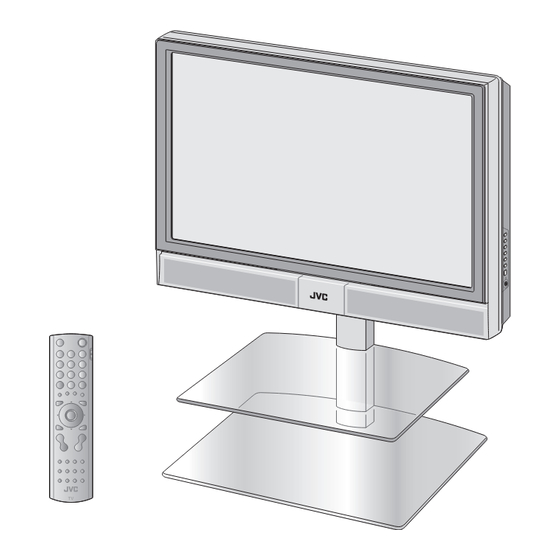
Page 97: Names Of All The Parts
Names of all the parts Switch between TV/AV TV / AV devices MENU Display on-screen menu / set Change channel / page Volume Remote control Illumination lamp Power On/Off sensor Illumination lamp lights Power lamp while the TV is on. To headphones (P. - Page 98 View in multi-picture mode (P. 28) Insert the batteries Use two AA/R6 dry cell batteries. Insert the batteries from the - end, making sure the polarities are correct. When choosing a favourite channel (P. 29) When operating a JVC VCR or DVD (P. 26)
-
Page 99: Basic Connections
When attaching the TV to the wall, use the 200mm optional JVC wall mounting unit Consult a qualifi ed technician. See the included manual on mounting procedures. JVC assumes no responsibility for damage due to improper mounting. 150mm 150mm 50mm... - Page 100 Connect a VCR / DVD recorder AERIAL Left side of Right side of back surface back surface EXT-1 EXT-2 VCR / DVD recorder After all the connections have been made, insert the plug into an AC outlet. Connect T-V LINK compatible recording device to EXT-2. T-V LINK "What is T-V LINK?"...
-
Page 101: Connecting External Devices
Connecting external devices You can connect many different devices to the rear panel of the TV. Please read the user manuals of each device before setting up. (Connecting cables are not supplied with this TV.) To EXT-3 R/L (PC IN) Check for PC compatibility "Technical information"... - Page 102 VCR / DVD / other devices Connect DVI devices : signal direction (P. 46) T-V LINK (P. 12) EXT-1 Watching videos Output Input · Composite · Composite signal / signal RGB / S-VIDEO · Sound L / R · Sound L / R Use S-VIDEO "S-IN"...
-
Page 103: Initial Settings
(In this manual, digital broadcasting is indicated as DTV, and analogue broadcasting as ATV.) (Set to "TV".) To the previous screen Exit If the "JVC" logo does not appear or TV/DTV MENU if you wish to make changes later DTV : "Automatic Seach" (P. 38) ATV : "AUTO PROGRAM"(P. - Page 104 Begin Shown only when powering on for the fi rst time. The power button on the remote control can also be used. Automatically register DTV channels Installation > Automatic Search Channels: BBC ONE BBC TWO BBC THREE BBC NEWS 24 BBCi CBBC Channel CH:68...
-
Page 105: Editing Dtv Channels
Editing DTV channels Edit the channels registered with "Automatic search" in "Initial settings" (P. 12). When coming from "Initial settings" (P. 12), skip to Confi rm Select DTV the channel picture Select Display the menu bar Delete a channel Delete Select "DTV"... - Page 106 Select "Select" EDIT PR LIST EDIT PR LIST BBC ONE BBC THREE select 1. BBC ONE 1. BBC ONE 2. BBC TWO 2. BBC TWO 7. BBC THREE 7. BBC THREE 30. CBBC Channel 30. CBBC Channel 40. BBC NEWS 24 40.
-
Page 107: Editing Atv Channels
Editing ATV channels Edit the channels registered with "AUTO PROGRAM" in "Initial settings" (P. 12). When coming from "Initial settings" (P. 12), skip to Move a Select ATV channel's position MOVE Display the menu bar Select "SET UP" Edit a select channel name... - Page 108 Begin Select a destination Finish >EDIT >EDIT select BBC1 BBC1 BBC2 BBC2 move out move in Begin Enter a channel name When selecting a preset name from the ID LIST >EDIT select >EDIT enter ID LIST (red) (blue) BBC1 the fi rst BBC1 BBC2 BBC2...
-
Page 109: Enjoying Your New Tv
Enjoying your new TV! Watching TV PAGE View channel information Change the aspect ratio Enjoy 3D sound Take snapshots of the screen Viewing teletext PAGE Enlarge the text To the index page Hold the current page Switch briefl y between teletext and TV Bookmark your favourite pages TV and Text tmode Using EPG... -
Page 110: Personal Preferences
Watching PAGE videos / DVDs Watch high quality video (S-VIDEO) Name connected devices Dub videos PAGE Personal preferences Adjust the picture Adjust the sound Use DTV (timer-record / confi guration / channel settings, etc.) Basic settings (channel settings, etc.) Advanced settings (sleep-timer / child lock, etc.) -
Page 111: Watching Tv
Watching TV Power on The green power lamp on the TV lights. Press again to turn the screen off and put the TV into standby mode. Channel Select ATV/DTV information and clock INFORMATION DTV : Digital broadcasting ATV : Analogue broadcasting Select a channel View subtitles Move up or down a channel... - Page 112 When DTV is selected Name of station Reception level Current ITV News CH61 programme Now: 13:00-14:00 Steve Scott 13:19 Next: 14:00-14:30 Steve Scott Time Following programme Channel When ATV is selected PR LIST PR LIST BBC1 Channel information Channels registered in "Initial settings"...
-
Page 113: Using Epg
Using EPG (Electronic Programme Guide) You can fi nd a programme from an eight-day programme guide, check its information, and make a reservation. Select DTV Display EPG Electronic Programme Guide 05:27 20/10/2004 GENRE 20/10 2. BBC TWO 04:00- History: Britain 1750-1900 21/10 7. - Page 114 Reservations After Reserve a At the start time, the Electronic Programme Guide 06:06 20/10/2004 GENRE programme channel will 20/10 2. BBC TWO 06:00- Big Cook Little Cook 21/10 7. BBC THREE 06:20- Tots TV 22/10 30. CBBC Channel 06:30- Bobinogs automatically change.
-
Page 115: Viewing Teletext
Viewing teletext This TV can display TV broadcasts and teletext on the same channel in two windows. Select ATV/DTV When ATV is selected When watching TV TEXT When DTV is selected Operate according to the screen indications When ATV is selected Enter a teletext page TEXT Move up or down a page... - Page 116 Hold the current page Hold the current page HOLD (ATV) Release Press again Display hidden information (answers to quizzes, etc) Reveal hidden pages REVEAL (ATV) Double the size of the displayed text Enlarge the text SIZE (ATV) To the Returns to page "100" index page or a previously designated page INDEX...
-
Page 117: Watching Videos / Dvds
VCRs and DVD recorders Turn on the device Select a channel (VCR mode) Rewind/Playback/Fast-forward Operate the VCR (DVD) To TV Stop/Pause Record/Display DVD top menu Select a chapter (DVD mode) Some models of JVC devices cannot be operated with this remote control. - Page 118 Advanced functions Display the menu bar Select "SET UP" Select "EXT SETTING" select select SET UP AUTO PROGRAM EDIT/MANUAL DECODER(EXT-2) COMPONENT AUTO SELECT EXT SETTING HDMI SETTING ATTENUATOR next next Select the EXT connected to S-VIDEO Set S-VIDEO input Switch The device >...
-
Page 119: Useful Functions
Useful functions Select the number of screens select Selecting " " returns to normal viewing mode Not available in PC mode. Watch in dual-picture mode E.g. You can watch TV and video at the same time. (For wide aspect ratio signals) Main Main Switch between... - Page 120 While the channel Press the number is displayed to register it on 1 - 4? (For 3 seconds) "NOT AVAILABLE" is displayed: Already registered Disappears after PROGRAMMED! a few seconds Recall the favourite channel Press the number you registered FAVOURITE 1 - 4? Register a channel to Customisations (P.
-
Page 121: Sleep Timer / Child Lock
Useful functions FEATURES FEATURES select "FEATURES" next Set a time FEATURES select for the TV to SLEEP TIMER CHILD LOCK "SLEEP TIMER" APPEARANCE TYPE A turn itself off BLUE BACK FAVOURITE SETTING ILLUMINATION BRIGHT SLEEP TIMER next > SLEEP TIMER select a time in minutes Cancel... - Page 122 FEATURES FEATURES select "FEATURES" next FEATURES Stop select SLEEP TIMER CHILD LOCK "CHILD LOCK" children from APPEARANCE TYPE A BLUE BACK FAVOURITE SETTING watching ILLUMINATION BRIGHT specifi c channels >> SET ID NO. CHILD LOCK enter an "ID NO." (a secret number of your choice) (ATV) to the next column >...
-
Page 123: Customising Your Tv
Customising your TV Display the menu bar PICTURE SOUND FEATURES SET UP DTV (P. 34) Select a menu select PICTURE next Selected menu's title Select an item PICTURE select STANDARD PICTURE MODE BRIGHT-1 CONTRAST BRIGHT-2 SHARP COLOUR COOL COLOUR TEMP. FEATURES To the previous screen... - Page 124 Menu Item Adjustments / Confi gurations PICTURE MODE Picture mode (BRIGHT / STANDARD / SOFT) BRIGHT-1 Backlight brightness (Darker Brighter) CONTRAST Contrast (LOWER HIGHER) BRIGHT-2 Brightness (DARKER BRIGHTER) SHARP Sharpness (SOFTER SHARPER) COLOUR Colour (LIGHTER DEEPER) Tint (REDDISH GREENISH) COLOUR TEMP. Colour temperature (WARM / NORMAL / COOL) FEATURES Finer picture adjustments (P.
-
Page 125: Using Dtv
Using DTV Timer-record setting DTV original function and setting, such as a recorder-linked timer-record setting, can be selected from the DTV menu. Select DTV Display the menu bar Select "DTV" select next Select an item select Rec Timer Configuration Edit PR List Recording Installation Common Interface... - Page 126 Select an "Inactive" column select Settings can be overwritten. REC TIMER 06:02 20/10/2004 Name Start Date Mode BBC ONE 00:00 00:00 01/01/2000 Inactive BBC ONE 00:00 00:00 01/01/2000 Inactive BBC ONE 00:00 00:00 01/01/2000 Inactive BBC ONE 00:00 00:00 01/01/2000 Inactive BBC ONE 00:00...
- Page 127 Using DTV AV setting Available for changing subtitle languages for DTV, favourite channel selection, changing PIN code, and upgrading the tuner software. Also, you can upgrade the tuner software as newer versions become available. Select DTV Display the menu bar Select "DTV"...
-
Page 128: Change Settings
Select a confi guration item select CONFIGURATION Audio Language English Subtitle English Favourite Mode Receiver Upgrade V.3.3 Enter PIN code Change settings : Change language Audio Language Subtitle : Channel selection method Favourite Mode Audio Language Switch languages (English / Welsh / Gaelic) Subtitle Select only DTV channels registered by using Favourite Mode... - Page 129 Using DTV Registration and setting Available for registration of DTV channels, initialisation of all DTV settings, and downloading software to use pay-per-view. Select DTV Display the menu bar Reset channel Select "DTV" registration select Register a new channel Initialise the next DTV settings Select an item...
- Page 130 Select an installation item select Installation Automatic Search Manual Search Factory Settings next Change setting : Reset channel registration Automatic Search Select "Yes" select Displays "Edit PR List" Installation > Automatic Search Channels: (P. 14) after registering BBC ONE BBC TWO BBC THREE channels.
-
Page 131: Advanced Picture Adjustment
Advanced picture adjustment By default, the TV automatically adjusts itself for the best picture. DIGITAL Display the menu bar Select "PICTURE" Super DigiPure select PICTURE next MOVIE Select "FEATURES" THEATRE select PICTURE PICTURE MODE STANDARD BRIGHT-1 CONTRAST BRIGHT-2 SHARP COLOUR COLOUR TEMP. - Page 132 level AUTO ( LOW ) AUTO To reduce AUTO(LOW) AUTO(HIGH) AUTO noise : When : When noise the picture appears loses sharpness AUTO ( LOW ) level AUTO natural-looking AUTO AUTO : Function is : When : When the picture outlines turned off noise appears...
-
Page 133: Troubleshooting
Troubleshooting Severe noise or snow Is the TV connected correctly to the aerial? Change the direction of the aerial. Is the aerial or its cable damaged? Consult your retailer Patterns, stripes or noise I can't turn it on! Is the power cord connected to the AC outlet correctly? Is the aerial receiving interference from high-voltage power lines or... - Page 134 Problem Actions page Is the ATV reception poor, too? Following the instructions in "Severe noise or snow" can solve this problem. Is there a DTV transmission tower nearby? Not displayed Turn "ATTENUATOR" to "ON", since the radio waves (black screen) are too strong.
- Page 135 Troubleshooting (continued) Problem Actions page Wrong screen size Switch SIZE in HDMI SETTING to "1" or "2". No sound Switch AUDIO in HDMI SETTING to ANALOGUE or DIGITAL. Green and Wait a little for the signal to stabilize when switching the signal format for an HDMI device.
-
Page 136: Ch/Cc List
Problem Actions page Deleting a DTV channel may cause an error message to An error message appear while other channels displayed. does not disappear Register channels again in "Automatic Search" CH/CC List To use the INSERT function (P. 16), fi nd the CH/CC number corresponding to the TV's channel number from this table. -
Page 137: Technical Information
Technical information What is T-V LINK? T-V LINK allows the TV to share information easily with a connected T-V LINK compatible device. By using T-V LINK : You can send the ATV channel information programmed on the TV to the T-V LINK compatible device, so that both the TV and the external device have the same channel settings. -
Page 138: Specifi Cations
Specifi cations Main unit Model LT-37DS6FJ Broadcasting systems CCIR, I Colour systems ·The EXT terminals also support the NTSC 3.58/4.43 MHz system. Analogue : E21-E69 (UNITED KINGDOM) Channels and frequencies IR A-J, E2-E12, E21-E69 (IRELAND) Digital : 474 MHz-850MHz (channel 21-68) Sound-multiplex systems NICAM (I) system. - Page 139 For users in the UK : If you have any problems setting up your new TV, please call the Helpline on 0870 330 5000. For users in the Republic of Ireland : If you have any problems setting up your new TV, please call the Helpline on 1890-582500.