Table of Contents
Advertisement
Advertisement
Table of Contents

Summary of Contents for Toyota 7FBEF 15
- Page 1 Index < Tillbaka till Servicemanual 7FBEF 15-20...
- Page 2 This manual has been edited for the vehicles launched into the market in May 2003. Any later change shall be informed through Toyota Industrial Equipment Parts & Service News. Please refer to the repair manual and parts catalog for the matters necessary for servicing.
-
Page 3: Table Of Contents
SECTION INDEX NAME SECTION GENERAL DEVELOPMENT OBJECTIVE ELECTRICAL SYSTEM POWER TRAIN TRAVELING, STEERING AND BRAKE SYSTEMS INSTRUMENTS FRAME AND AUXILIARY EQUIPMENT MATERIAL HANDLING AND HYDRAULIC SYSTEM SAS CONTROL SYSTEM OUTLINE OF MAJOR OPTIONS APPENDIX... -
Page 4: General
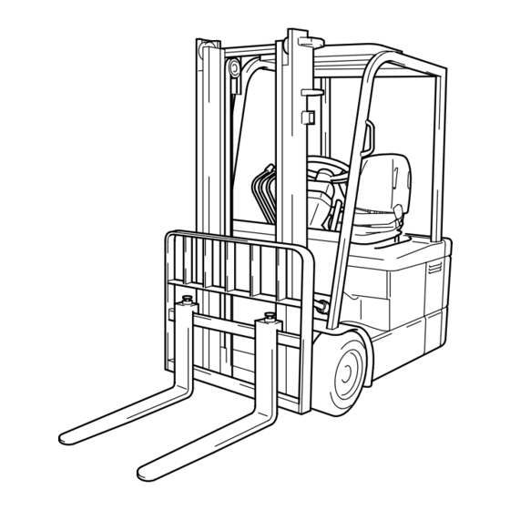
GENERAL Page VEHICLE EXTERIOR VIEWS ........0-2 MODEL LINEUP .............. 0-3... - Page 5 VEHICLE EXTERIOR VIEWS Vehicle exterior views Front View Rear View...
- Page 6 MODEL LINEUP Vehicle model lineup Payload New model Previous model Voltage (L.C. 500 mm) 1.5 ton 7FBEF15 5FBE15 − 1.6 ton 7FBEF16 1.8 ton 7FBEF18 5FBE18 − 2.0 ton 7FBEF20 L.C.: Load center...
- Page 8 DEVELOPMENT OBJECTIVE Page DEVELOPMENT OBJECTIVE ........1-2 FEATURES (SELLING POINTS) ........ 1-3 MAJOR DIFFERENCES BETWEEN NEW AND PREVIOUS MODELS ..........1-9...
-
Page 9: Development Objective
DEVELOPMENT OBJECTIVE I Development objective Toyota 5FBE series, 1,500-kg to 1,800-kg three-wheel, counter battery type forklift have favorably been accepted by a large number of customers thanks to their ease of use and reliability since the model change in 1993. - Page 10 FEATURES (SELLING POINTS) I Major selling points The greatest feature of the new models is adoption of the AC motor drive system. New features of the 7FB series have also been adopted in many places. 1. Adoption of AC Motor Drive System What is AC motor drive system? The conventional DC motor drive system uses a controller for battery current chopping (ON and OFF) to control the motor power by changing the chopping ratio to realize from inching at the time of starting...
- Page 11 Features of AC motor drive system The table below shows three major features of the AC motor drive system. The AC motor drive system has already been adopted in the industrial world by making the most of these features. System feature Product feature Realization of higher performance in the same Simple, compact motor structure...
- Page 12 H mode P mode S mode 5FBE15 STILL R20 Cycle time Operation time (TOYOTA 30m operation cycles) (DIN 4PzS 440L, TOYOTA 30m operation cycles) sec/cycle 11%UP H mode P mode S mode 5FBE15 H mode P mode S mode 5FBE15...
- Page 13 3. Improved Efficient Operation Hour The accelerator-off regeneration system is added to the AC drive system for longer operation compared to the previous models. The power up function is also adopted for longer efficiency operation hours. Power keep function (Setting to the P mode at the Efficiency-preference and the S mode for Operation-hour-preference) The power keep function has been developed as the new control in new models for maintaining the discharged battery performance by making use of the wider motor control range of the AC motor drive system.
- Page 14 4. Easy Ingress/Egress and Dwelling Ability Easy Ingress/Egress An open step is provided for easy ingress/egress. The tilt steering is also provided with a memory as on the 7FB series to allow full forward tilting of the steering column to ensure smoother ingress/egress. Step height Step height 545mm...
- Page 15 6. Safety Functions The new models are installed with the SAS safety functions adopted on the 7FB series to ensure equivalent safety. Though the safety functions are summarized below, refer to the SAS Control Equipment section for further details. Safety Function List Safety control Functional outline Decreases the front tilt angle at a high fork height...
- Page 16 MAJOR DIFFERENCES BETWEEN NEW AND PREVIOUS MODELS −:Not applicable New models Previous models Item Applicable Applicable models models 1385 mm 1.5 ton 1295 mm All models Wheel base 1490 mm 1.6 to 2.0 ton − − General 1070 mm 1.5 to 1.8 ton 1075 mm All models Overall width...
- Page 17 1-10...
- Page 18 ELECTRICAL SYSTEM Page BATTERY ................2-2 MOTORS ................2-4 MAIN CONTROLLER ............ 2-10...
- Page 19 BATTERY I General 1. Battery Compartment and Necessary Weight When purchasing the battery locally, always adjust the weight to satisfy the minimum weight shown in the table below. Minimum required battery Compartment dimensions mm (in) Vehicle model Remarks weight (with case) Kg (lb) Length X Width Y Height Z...
- Page 20 2. Battery Specifications No batteries are provided. Please use the batteries conforming to DIN 43 531A. Use 320A connectors. RIGHT LEFT (7.1) FRONT 320A CONNECTOR 3. Battery List The table below shows recommended batteries. Refer to the general description for batteries with regard to the minimum required weight. DIN 43 531A Installed battery Battery case...
- Page 21 MOTORS Drive motor I General 1. A compact, high-performance, maintenance-free AC induction motor optimum for battery forklift trucks has been newly developed as the drive motor. 2. The motor is maintenance-free because it has no brush. I Specifications Rated output Size Voltage Mass...
- Page 22 I Structure and principle of AC induction motor The AC induction motor has no brush and commutator unlike the conventional DC motor, so there is no sliding part. It, therefore, has the following features: 1. The motor size can be reduced by dimension L for the brush and commutator if the output is the same. 2.
- Page 23 I Motor operation principle Right-hand screw rule and Fleming's rule are to be explained here before explanation on the motor operation principle. 1. Right-hand screw rule Raise the thumb of the right hand with other fingers Direction of folded. When the thumb is placed in the current current flowing direction in this state, the magnetic field is Magnetic...
- Page 24 Operation principle 1. When a current flows in a fixed direction in the field winding as shown below, magnetic field is generated around the field winding as illustrated according to the right-hand screw rule and magnetic poles (N and S poles) are generated. 2.
- Page 25 7. The rotational magnetic field is as explained below. (1) Assume that three coils are placed on the outer side the rotor. When these three coils (a1-a2, b1-b2 and c1-c2) are connected and a three phase alternate current flows, the magnetic flux varies as shown in the figure below to generate a 2-pole rotational magnetic field.
- Page 26 Pump motor I General 1. An AC induction motor most suitable for compact, high-performance, maintenance-free battery forklift trucks is adopted newly as the pump motor just like the drive motor. 2. The motor output is increased by making use of the induction motor to improve the performance both in loaded and unloaded states.
- Page 27 2-10 MAIN CONTROLLER I General AC System This controller is multi-functional making use of most advanced electronic technologies such as inverter control using a microcomputer, the function for CAN communication between the main controller and the drive/pump motor driver, and the function for communication with multi-screen display. The power select and power keep functions have been realized by making use of the AC motor drive system features.
- Page 28 2-11 I Controller configuration Traveling/Material Handling Controller System Configuration Drive motor thermo-sensor Drive Traveling Drive rpm sensor AC driver motor Drive motor thermo-sensor Drive Traveling Drive motor rpm sensor AC driver motor Direction switch Traveling accelerator potentiometer Battery Brake switch Main Tire angle sensor controller...
- Page 29 2-12 Internal Configuration of Traveling/Material Handling Controller Battery Traveling/material handling controller Main controller Power supply CPU board contactor Cooling fan Drive Sensors and Traveling AC driver switches motor Drive Traveling AC driver motor EEPROM Material handling Pump AC driver AC motor Solenoid Display drive...
- Page 30 2-13 I Major controller functions 1. Two traveling motor control Two independent AC drive systems are adopted for controlling the motors for front wheels LH and RH. The outputs from motors LH and RH are controlled according to the steering angle for smooth operation.
- Page 31 2-14 17. Return-to-neutral function When the direction lever is in the forward or reverse position or when the key switch is turned on while the accelerator pedal is depressed, traveling is disabled unless the direction lever and accelerator pedal are returned to their neutral positions. 18.
-
Page 32: Power Train
POWER TRAIN Page DRIVE UNIT ..............3-2... - Page 33 DRIVE UNIT I Difference from previous models The drive unit size has been reduced by changing the train of gears from that on previous models, and the motors LH and RH are arranged transversely on the same axis. I General 1.
- Page 34 TRAVELING, STEERING AND BRAKE SYSTEMS Page ACCELERATOR .............. 4-2 REAR AXLE ..............4-3 TIRES ................. 4-4 STEERING ................ 4-6 BRAKE ................4-10...
- Page 35 ACCELERATOR I Standard Pedal The accelerator is mounted on the front protector bracket. A plastic pedal is adopted as on the conventional models for smooth start in depression. The pedal effort is decreased from 1.5 kg to 0.7 kg by revising the accelerator structure. I D2 pedal (option) The accelerator pedal and the direction switch are integrated.
- Page 36 REAR AXLE I General Double tires are installed as the standard feature for rear wheels of all vehicle models for longer tire life.
- Page 37 TIRES I General 1. Pneumatic shaped cushion (PSC) tires are adopted as standard tires. The table below shows standard tires. 2. Pneumatic tires are adopted optionally for the 1.5- to 1.8-ton models. 3. See the OPTION LIST for details of the optional tires. Standard Tire Setting List Front tire Vehicle...
- Page 38 I Option list Front Tire Model Tire Tire name Tire Wheel Wheel brand Tire size 7FBEF15 7FBEF16 7FBEF18 7FBEF20 specification specification size U-LUG 18×7−8/4.33 Sidering 4.33R-8 WATTS Tire U-LUG 200/50-10/ Sidering 6.50F-10 WATTS Tire 6.50 Pneumatic shaped cushion J-LUG 18×7−8/4.33 Sidering 4.33R-8 F01B...
- Page 39 STEERING Steering system I General Power Steering System Full hydraulic steering system is adopted as the standard as on the previous models. The power steering system on the previous models has used an exclusive motor pump to supply hydraulic oil to the power steering system. On the new models, the hydraulic oil from the oil pump is shunted by the priority valve to supply hydraulic oil at an appropriate pressure to each power system.
- Page 40 Priority valve I Operation When the key switch is OFF The spool in the priority valve is located to the left of the control spring. P (Oil pump) Spool Control spring When no steering operation is performed Hydraulic oil flows from the pump through the spool to PP and LS pilot line. As the CF line in the steering valve is shut and the pilot line is drained, internal pressure of CF goes through inside the spool to PP and to the LH chamber, pushing the spool to the right side of the figure.
- Page 41 As the spool is pushed to the right side, the EF line circuit opens, allowing almost all the pump discharge to flow from the EF line to the control valve. When steering operation is performed Turning the steering wheel opens the control orifice in the steering valve and opens the CF line. The lower side pressure of the control orifice goes through the LS pilot line to the RH chamber, generating the pressure difference with the LH chamber in which the pressure is equal to that of the upper control orifice.
- Page 42 Steering system I General The rack and pinion of the turning drive portion in the full hydraulic power steering system are made compact with integration. Removal and installation of the rear axle including the rack and pinion have become easier. Previous Pinion PS cylinder...
- Page 43 4-10 BRAKE Brake pedal I General 1. The brake structure is changed from the hydraulic to the mechanical type on all models. 2. The pendant pedal link structure is adopted as on the previous models. I The regenerative brake The regenerative brake sensor use a limit switch not only to improve the sensor system reliability but also to facilitate maintenance when readjustment of the regenerative brake becomes necessary.
- Page 44 4-11 Front brake I General Hydraulic parts such as the master cylinder are discontinued by adoption of mechanical disc brake that has excellent maintainability. I Brake specifocations Foot brake Mechanical disc brake Type Parking brake Mechanical disc brake Brake disc outside diameter mm (in) 203 (8.0) Brake effective diameter mm (in) 165 (6.5)
-
Page 45: Parking Brake
4-12 Parking brake I General The lever type (ratchet type) is adopted as on previous models. The grip portion is shaped for easy gripping. Previous model New model I Structure When the brake lever is pulled from position A to position B in the figure below, the disc brake is mechanically applied through a wire cable. -
Page 46: Instruments
INSTRUMENTS Page MULTIPLE DISPLAY ............5-2 GENERAL FUNCTIONS ..........5-10 DIAGNOSIS ..............5-15 MASK FUNCTIONS ............5-21... - Page 47 MULTIPLE DISPLAY I General The multiple display indicates various types of vehicle information by switching the screen according to need. Display and Buttons Initial screen upon key switch on Y O T A U I P P E S P H S P H MENU (1) (2)
- Page 48 (1) Parking brake ON indicator This indicator comes on when the parking brake is activated. If the accelerator pedal is depressed with the direction lever in the forward or reverse position, beeps sound to warn the operator. (2) 2-speed travel speed set indicator Each time the button is pressed, the indicator comes on or goes out.
- Page 49 Description of control Overheat Specifica- Mode section tion Primary control Secondary control Tertiary control 1. Character indication 1. Character indication and indicator blink and indicator blink − 2. Buzzer for 5 2. Buzzer continues seconds 3. Change to half 3. Change to S mode throttle 1.
- Page 50 (5) Battery charge indicator This indicator indicates the remaining battery charge in 10 stages. A: Low remaining battery charge warning The battery charge indicator blinks when the remaining battery charge drops to the set level or below. When the key switch is turned from OFF to ON in this state, a buzzer sounds for 5 seconds to warn the operator.
- Page 51 (11) Low temperature warning indicator Warn the low temperature of the traveling and material handling AC drivers. When the material handling AC driver temperature becomes low, a buzzer sounds to warn the operator for 5 seconds. At the same time, it restricts the material handling output. The low temperature section indication blinks.
- Page 52 I Display indication list GENERAL screen To be selected by the user 2-speed travel speed ON/OFF ON or OFF setting of 2-speed travel speed Switching to hour meter display Checking traveling or material handling system operation time Power select Power mode selection To be set by the user Traveling speed level Setting of 2-speed travel speed level...
- Page 53 I Abbreviations display on the screen Abbreviation Meaning Abbreviation Meaning Attachment switch 1 SSD2 Drive motor 2 rpm sensor Attachment switch 2 Pump motor rpm sensor Controller Steering angle sensor Traveling AC driver STS1 Steering angle sensor 1 Drive motor STS2 Steering angle sensor 2 Steering angle sensor for straight...
- Page 54 I General functions 1. General functions can generally been used or seen by the user. 2. Two types of multiple displays are available: the easy model (the standard specification), and the all- round model (OPT). The display contents vary as follows: :Not provided : General function Model...
- Page 55 5-10 GENERAL FUNCTIONS I Changing Display Button (1) Button (2) 2-speed travel speed ON/OFF setting Hour meter display 3 0 / GENERAL screen selection S P H S P H Power control selection MENU Button (3) Press button (3) for 2 seconds or more. 2-SPEED TRAVEL SPEED S P E E D L E V E L...
- Page 56 5-11 I Operating procedure of function setting GENERAL screen 1. 2-speed travel speed on/off selection Press button (1) for 2-speed travel speed control on/ 2-speed travel speed indicator off. The 2-speed travel speed is on if the indicator comes on. Button (1) 3 0 / S P H...
- Page 57 5-12 Model Easy All-round Description model model Function Key ON hour meter Indicates the total key ON time Traveling hour meter Traveling operation time C Material handling hour meter Material handling operation time Total time of traveling and material handling Traveling/material handling operation (when both operations occur at the ...
- Page 58 5-13 POWER CONTROL FUNCTION SELECTION screen The travel and material handling power control levels can be set independently using this screen. 1. Press button (1) on the POWER CONTROL Button (1) Button (2) FUNCTION SELECTION screen, select “YES” and press button (3) to display the TRAVEL POWER CONTROL LEVEL SETTING screen.
- Page 59 5-14 CLOCK SET FUNCTION SELECTION screen The year, month, day, day of week, time and 12/24-hour display can be set independently. Press button (2) on the POWER CONTROL FUNCTION SELECTION screen, select “NO”, and press button (3), or press button (3) on the MATERIAL HANDLING POWER CONTROL LEVEL SETTING screen to display the CLOCK SET FUNCTION SELECTION screen.
- Page 60 5-15 DIAGNOSIS 1. When diagnosis is activated, the diagnosis ON Wrench symbol indicator comes on and blinks on the screen and a beep sounds to warn the operator that some abnormality has occurred on the vehicle. 2. Also, up to three diagnosis error codes are displayed 1 2 3 4 5 on the screen.
- Page 61 5-16 Diag Displayed Detection memory Faulty Phenomenon on vehicle code controller code Forward and backward tilt SWs: 63-1 63-1 simultaneously on ·No forward tilt restriction Forward tilt SW: Short circuit for more than 2 63-2 63-2 ·No automatic leveling minutes (Forward tilt disabled) Backward tilt SW: Short circuit for more than 63-3...
- Page 62 5-17 Diag Displayed Detection memory Faulty Phenomenon on vehicle code controller code Restricted traveling out- A2-1 CPU board overheat Restricted traveling out- DCR_LH, A2-2 DCR_LH or DCR_RH board overheat DCR_RH Restricted material han- A2-3 PCR board overheat dling output ·Traveling disabled ·Material handling and Incorrect battery connection power steering disabled...
- Page 63 5-18 Diag Displayed Detection memory Faulty Phenomenon on vehicle code controller code AF-1 AF-1 CPU abnormality (1) ·Traveling disabled AF-2 AF-2 CPU abnormality (2) ·Material handling dis- abled AF-3 AF-3 CPU abnormality (3) ·Power steering disabled AF-4 AF-4 CPU abnormality (4) C1-1 C1-1 DCR_LH current sensor offset abnormality...
- Page 64 5-19 Diag Displayed Detection memory Faulty Phenomenon on vehicle code controller code EF-1 EF-1 EEPROM abnormality (1) Operate under the default EF-2 EF-2 EEPROM abnormality (2) Operate under the default EF-3 EF-3 CPU abnormality Display only EF-4 EF-1 EEPROM abnormality (3) Operate under the default Communication abnormality from C/R to dis- F1-1...
- Page 65 5-20 Diag Displayed Detection memory Faulty Phenomenon on vehicle code controller code H6-1 *1 H6-1 Tilt a2 (FRONT) solenoid abnormality (1) Tilt operation stop Material handling dis- H6-2 *1 H6-2 Tilt a2 (FRONT) solenoid abnormality (2) abled H6-3 *1 H6-3 Tilt b2 (REAR) solenoid abnormality (1) Tilt operation stop Material handling dis-...
- Page 66 5-21 MASK FUNCTIONS I General In addition to the functions described in the instruction manual for use by general users, the multiple display provides the following mask functions for use by the service staff for vehicle maintenance and specification setting. The mask functions are protected by password to prevent damage of the data by unintentional operation by users.
- Page 67 5-22 Preparation for the MASK MENU screen Caution: When going to the MASK MENU screen from the general screen, always jack up the vehicle until the drive wheels (front tires) leave the ground, and support the vehicle with wooden blocks under the front frames.
- Page 68 5-23 I Password Notes on password input 1. Be sure to operate buttons for the display with your finger. If a sharp-edged tool is used, the button may be damaged. 2. If a mistake is made part of the way through, turn the key switch to OFF and begin again. If the MASK MENU screen does not appear after several attempts, the system may be faulty.
- Page 69 5-24 Operation on MASK MENU screen Caution: Unlike the analyzer function selection on of previous models, display of test screen does not prohibit the vehicle’s ordinary operation. 1. Input the password on the general screen (see page 5-23) to display the MASK MENU screen. 2.
- Page 70 5-25 I Analyzer General 1. The analyzer supports inspection and troubleshooting of the control system using the communication function between the traveling/material handling controller and the display. 2. Setting the display into the ANALYZER screen makes it possible to inspect and detect abnormality in functions of the operating system and sensors, such as main traveling, material handling, EHPS, SAS circuits and the accelerator.
- Page 71 5-26 Analyzer menu screen list *Values shown in the 2nd column are display examples and not the standard values. Display ANALYZER MENU Meaning screen 1st column 2nd column DIAG-1 to Error code and DIAG MEMORY Error display DIAG-10 detection time Main drive circuit 1 temperature (heat sink): °C I/O 1-1 THCD: +25/+25...
- Page 72 5-27 Display ANALYZER MENU Meaning screen 1st column 2nd column L: −.−− −.−− 1− Lift switch: 0 (OFF), 1 (ON) Lift lever angle 1 sensor voltage: V I/O 3-1 Lift lever angle 2 sensor voltage: V L:0.90 3.50 10 Lift raise switch: 0 (OFF), 1 (ON) Lift lower switch: 0 (OFF), 1 (ON) L (SOL):−.−−...
- Page 73 5-28 Display ANALYZER MENU Meaning screen 1st column 2nd column I/O 4-1 STS:001 Steering angle sensor pulse: 0 (OFF), 1 (ON) K-POS:159 I/O 4-2 Steering angle knob position: Actual (target) (150) I/O MONITOR4 (Steering Deviation of steering angle knob position K-DIFF:100 control) I/O 4-3...
- Page 74 5-29 Operation procedure 1. Input the password on the GENERAL screen (see page 5-23) to display the MASK MENU screen. 2. Check that “1. ANALYZER” is displayed on the MASK MENU screen and press button (3) (enter) to display the ANALYZER MENU screen. 3.
- Page 75 5-30 Diagnosis Memory Function (DIAG MEMORY) The controller stores up to 10 of the most recent errors. The DIAG MEMORY screen displays these diagnosis error codes together with their detection time (as key ON hour meter reading). The most recent diagnosis error code is displayed as DIAG-1, followed by DIAG-2, DIAG-3 and so on to DIAG-10.
- Page 76 5-31 Vehicle Abnormalities Not Stored in Diagnosis Memory Some abnormalities are not stored in diag memory even when the controller detects it and warn the operator. Warning indicators Warning method Displayed code • Indication Parking brake ON warning: Parking brake ON Warns if the direction switch is turned to the for- warning indicator ward or reverse position and the vehicle travels...
- Page 77 5-32 monitor This function displays the analog input voltage from each Detected error code Activated of traveling, material handling and SAS sensors. at present function No Monitoring the displayed values enables the quality of each circuit/sensor to be judged. When any abnormality is detected, it is displayed as an error code on the screen.
- Page 78 5-33 (3) I/O 1-3 screen I/O 1-2 screen TD: Drive motor (1) (2) temperature (°C) Temperatures of the drive motor (1) (2) is displayed. Button (2) • Checks if the temperature measurement function is Button (1) (3) I/O 1-3 screen functioning properly.
- Page 79 5-34 (9) I/O 1-9 screen VBKS: Key start voltage (V) I/O 1-8 screen Power source voltage of traveling and material Button (2) handling AC drivers are displayed. Button (1) Standard: 48 V (9) I/O 1-9 screen (10) I/O 1-10 screen VBSOL: Solenoid power supply voltage (V) Solenoid power source voltage is displayed.
- Page 80 5-35 I/O monitor 2 Displays each switch ON/OFF state and analog input voltages from sensors for traveling and swing control. Operation procedure 1. Display the ANALYZER MENU screen. 2. Press button (2) twice. 3. Check that “3. I/O MONITOR2” is displayed and press button (3) (enter).
- Page 81 5-36 (2) I/O 2-2 screen Direction switch inspection. I/O 2-1screen DSF: Forward traveling switch DSR: Reverse traveling switch Button (2) Indication Button (1) Operation (2) I/O 2-2 screen Forward traveling 1 (=ON) 0 (=OFF) Neutral 0 (=OFF) 0 (=OFF) < I / 0 2 2 >...
- Page 82 5-37 I/O monitor 3 This function displays the ON/OFF status of material handling and mast control switches and analog input voltages from sensors. Operation procedure 1. Display the ANALYZER MENU screen. 2. Press button (3) three times. 3. Check that “4. I/O MONITOR3” is displayed and press Button (1) button (3) (enter).
- Page 83 5-38 (3) I/O 3-3 screen I/O 3-2 screen Standard models T: Forward and backward tilt switch inspection Button (2) (3) I/O 3-3 screen Forward Backward Button (1) Operation Display Standard models tilt switch tilt switch T: −.−− −.−− 10 Forward tilt 1 (=ON) 0 (=OFF) Neutral...
- Page 84 5-39 (6) I/O 3-6 screen I/O 3-5 screen Standard models A1(SOL): Unused Button (2) (6) I/O 3-6 screen 3-way and 4-way mini lever models (OPT) Button (1) Standard models A1 (SOL): Attachment 1 proportional valve solenoid current (A) Judge the output quality to attachment (1) proportional <...
- Page 85 5-40 (9) I/O 3-9 screen SWTK: Automatic fork leveling cancel switch inspection I/O 3-8 screen 0 = OFF Button (2) 1 = ON Button (1) Operate the tilt knob switch to judge ON/OFF quality. (9) I/O 3-9 screen (10) I/O 3-10 screen SSP: Pump motor rpm [target rpm] 9 >...
- Page 86 5-41 I/O monitor 4 ON/OFF state of knob steering synchronizer and other switches and the analog input value from each sensor are indicated. Operation procedure 1. Display the ANALYZER MENU screen. Button (1) 2. Press button (2) four times. Button (2) ANALYZER MENU screen 3.
- Page 87 5-42 (2) I/O 4-2 screen K-POS: Actual value of knob position (target) I/O 4-1 screen Actual value: Button (2) Knob position computed by the controller from the Button (1) steering angle sensor signal. (2) I/O 4-2 screen Target value: Knob position computed by the controller from the tire angle sensor signal.
- Page 88 5-43 Active test This function outputs ON/OFF signals to each switch related to the electrical system and compares controller input signals with those signals. Operating Procedure 1. Display the ANALYZER MENU screen. 2. Press button (2) five twice. 3. Check that “6. ACTIVE TEST” is displayed and press Button (1) button (3) (enter).
- Page 89 5-44 (3) ACT-3 screen Standard models ACT-2 screen PSOL: Unused Mini lever models (OPT) Button (1) PSOL: Unload valve solenoid (3) ACT-3 screen Button (2) 1: Signal check line ON (error) Standard models 0: Signal check line OFF (normal) • Turn the key switch to ON and operate the material handling lever.
- Page 90 5-45 I Tuning General This function performs fine adjustment of traveling and material handling controls. When the use requests to limit the maximum speed or weaken the regenerative braking force, each setting can be performed on the TUNING screen in the procedures same as power control level setting. 59 tuning items are prepared including spares.
- Page 91 5-46 Level ( : Initial setting position) Tuning Item Lift lowering adjustment (1): Adjusts solenoid output current at the beginning Small Large of lift lowering operation. Lift lowering adjustment (2): Slow Fast Adjusts inching speed during lift lowering operation. Lift lowering adjustment (3): Adjusts the maximum solenoid output current during Small Large...
- Page 92 5-47 Level ( : Initial setting position) Tuning Item Backward tilt adjustment (2): Slow Fast Adjusts inching speed during backward tilt operation. Backward tilt adjustment (3): Adjusts the maximum solenoid output current during Small Large backward tilt operation. Backward tilt adjustment (4): Weak Strong Adjusts acceleration during backward tilt operation.
- Page 93 5-48 Level ( : Initial setting position) Tuning Item Attachment 2 lowering adjustment (3): Adjusts the maximum solenoid output current during Small Large lowering operation of attachment 2. Attachment 2 lowering adjustment (4): Adjusts acceleration during lowering operation of Weak Strong attachment 2.
- Page 94 5-49 TUNING Screen Operating Procedure 1. Input the password on the GENERAL screen (see page 5-23) to display the MASK MENU screen. 2. Press button (2) to display “2. TUNING” and press button (3) (enter) to display the TUNING MENU screen.
- Page 95 5-50 TUNING 1 Button (1) Button (2) This function sets the tuning level of the standard TUNING MENU screen functions. Operation procedure = T U N M E N U = 1. Display the TUNING MENU screen. T U N I N G 1 S P H 2.
- Page 96 5-51 TUNING 2 LIFTV This function changes the tuning level of the lift lever. Operation procedure 1. Display the TUNING MENU screen. 2. Press button (1) or (2) to display “2.TUNING2 LIFTV” Button (1) Button (2) and press button (3) (enter) to display TUNING level TUNING MENU screen setting screen.
- Page 97 5-52 TUNING 3 TILTV This function changes the tuning level of the tilt lever. Operation procedure 1. Display the TUNING MENU screen. 2. Press button (1) or (2) to display “3.TUNING3 TILTV” Button (1) Button (2) and press button (3) (enter) to display TUNING level TUNING MENU screen setting screen.
- Page 98 5-53 TUNING 4 ATT1V This function changes the tuning level of the attachment 1 lever. Operation procedure 1. Display the TUNING MENU screen. 2. Press button (1) or (2) to display “4.TUNING4 ATT1V” Button (1) and press button (3) (enter) to display TUNING level Button (2) TUNING MENU screen setting screen.
- Page 99 5-54 TUNING 5 ATT2V This function changes the tuning level of the attachment 2 lever. Operation procedure 1. Display the TUNING MENU screen. 2. Press button (1) or (2) to display “5.TUNING5 ATT2V” Button (1) Button (2) and press button (3) (enter) to display TUNING level TUNING MENU screen setting screen.
- Page 100 5-55 I Option set Option set menu list Selection Indication Description Indi- Indi- Meaning Meaning cation cation Enables simultaneous operation of OPT-1 DEMO MODE traveling and material handling before Enable Disable starting the hour meter. OPT-2 H/M START Starts hour meter count. Counting counting Disables level setting of traveling/material...
- Page 101 5-56 Caution: • These functions are used to adjust the controller and display control according to the options installed on the vehicle; they do not enable or disable the actual function of the options. O F F • When the controller board is replaced, it is S P H S P H necessary to reset it according to the vehicle...
- Page 102 5-57 OPT-3 screen OPT-16 screen Button (1) Button (2) Press b utton < > < > T Y P E 1 / 2 D E S T I J / I S P H S P H S P H S P H MENU MENU...
- Page 103 5-58 OPT-15 screen Button (2) Button (1) Not used < > 3 6 V Y / N S P H S P H MENU Button (3) Press button (3) < > W A Y L V E Y / N S P H S P H MENU...
- Page 104 5-59 I Matching General Of the sensors used for SAS, the signal voltage values of the tilt angle, load and tire angle sensors in the mast vertical position, no load state, and tire straight travel position respectively are stored in the controller at the time of vehicle shipment to be used as the bases for control.
- Page 105 5-60 Before matching Vehicle should be in the “Standard state” for matching. “Standard state” means the vehicle satisfies the following conditions: 1. Tire pressure check Make sure that the tire pressure is at the specified V mast level. Low pressure and deviation of tire pressure among the tires may hinder accurate matching.
- Page 106 5-61 *: Press button (3) on the ATT2 matching set screen to display the MASK MENU screen. OK on the display is indicated only after matching (by pressing button (2)). The value in parentheses is the one stored at present. The value outside parentheses is the one under the present vehicle condition.
- Page 107 5-62 I Tire constant set General In order to optimize the speed meter, tire constant that matches the tire outside diameter needs to be input in the controller. Although the tire constant is set on a new vehicle at shipment from the factory, adjust it whenever the tire size is changed or the tires are worn excessively to a degree affecting the speedometer function.
- Page 108 FRAME AND AUXILIARY EQUIPMENT Page BODY FRAME ..............6-2 INSTRUMENT PANEL AND ADJACENT PORTION ..........6-8 AUXILIARY EQUIPMENT ..........6-10 FUSES ................6-13...
- Page 109 BODY FRAME Frame I General Round-type front stay Cautions for jacking up Side cover Cautions for hoisting the vehicle 1. Round-type front stay • The newly adopted round-type front stay facilitates ingress/egress. 2. Elimination of side covers • Side covers on previous vehicles are eliminated and replaced with structural members to strengthen the lower portion of the frame.
- Page 110 3. Cautions for jacking up • A jack-up point is provided at the bottom of the frame to the rear of the front tire. • The jack-up point is provided within a range of 150 mm (5.9 in) from the fender. Jack up the vehicle at the specified jack-up point.
- Page 111 Battery hood I General 1. A press-integrated hood wholly covers the top of the battery. This hood opens up fully for the ease of battery maintenance and replacement. 2. Use the notch of the head guard to replace the battery from the right-hand side of the vehicle. I Battery hood opening/closing procedure Caution: When opening/closing the battery hood, hold the handle on the right-hand side of the hood.
- Page 112 I Battery hood locking device • To fix the battery hood securely for operation, a locking device and a catch are provided on the front end of the hood. • The locking device automatically locks the hood when closed as a fail safe locking mechanism. The catch prevents looseness of the hood by means of cushion rubber.
- Page 113 Step 1. An open step is adopted for the new model. The step height is much reduced compared to previous models for easier ingress/egress. 2. The top surface of the step is designed for both slip-resistance and easier cleaning. Step height mm (in) Previous model 545 (21.5)
- Page 114 Floor mat The new model is provided with a floor mat on top of the toe board. Seat I General A seat switch function is added to the Grammar seat favorably accepted on the 7FGF25 series. A fabric seat (Grammar) is adopted optionally. I Major Features 1.
- Page 115 INSTRUMENT PANEL AND ADJACENT PORTION I Layout near operator’s seat (9) (10) (11) (12) (13) (14) Pattern of shift (17) Layout of Pedal (16) (18) (15) D2 Pedal (OPT) Name Name Parking lever (10) Control lever (for tilting) Horn SW (11) Control lever (for attachment) Direction lever (12) Control lever (for attachment) (optional)
- Page 116 Instrument panel I General 1. Novel design is realized with resin molding. 2. The instrument panel consists of 2 halves using sturdy and environmentally friendly polypropylene as the material. 3. The downsized instrument panel improves the ease of ingress/egress. LH Instrument panel RH Instrument panel...
- Page 117 6-10 AUXILIARY EQUIPMENT I Direction switch 1. Difference from previous models The direction switch is the same as that installed on the 7FGF25 series. 2. Direction lever (1) The direction switch is of the lever type easily operable with fingers as on the 7FGF25 series. (2) The direction switch is positioned on the left-hand side as a standard component.
- Page 118 6-11 I Lights 1. List of lights Type of light Specifications Bulb Head light OPT Same as on the previous model 10W(Clearance, upper) Front combination light OPT Same as on the previous model 25W(Flasher, lower) High-mount, transverse rear combi- 25W(Flasher, outer) nation lights are installed as stan- 25W/10W Rear combination light...
- Page 119 6-12 2. Light switch Light switch is positioned on the right-hand side of the steering column for improved operability. Two-stage light switch turns the side clearance lights and taillights ON and OFF in the first stage and the headlights, side clearance lights and tail lights ON and OFF, in the second stage. Turn signal switch Light switch Switch for rear working...
- Page 120 6-13 FUSES I Installed positions Fuses F1 and F4 to F6 are installed in the controller box located under the rear right-hand section of the vehicle. F1 is of the module type while F4 to F6 are of the blade type. Previously independent F1 for traveling and F2 for material handling are integrated as F1 fuse for traveling and material handling.
- Page 121 6-14...
-
Page 122: Material Handling And Hydraulic System
MATERIAL HANDLING AND HYDRAULIC SYSTEM Page V MAST ................7-2 FV MAST ................7-3 FSV MAST ................ 7-4 MATERIAL HANDLING SPEED ........7-5 LOAD BACKREST & FORK ........7-6 TILT CYLINDER .............. 7-7 OIL PUMP ................. 7-8 OIL TANK ................7-9 OIL CONTROL VALVE .......... - Page 123 V MAST I General 1. The vehicle is installed with the V mast as the standard component. The mast installation method is changed from that for the previous models to reduce the lost load center (distance from the front axle center to the fork front). 3.
- Page 124 FV MAST I General 1. The FV mast is optionally available. 2. The mast installation method is changed from that on previous models to reduce the lost load center (distance from the front axle center to the fork front). 3. A mast for 2.0 tons is not provided. I Major improvements 1.
- Page 125 FSV MAST I General 1. The FSV mast is optionally available. 2. The mast installation method is changed from that for the previous model to reduce the lost load center (distance from the front axle center to the fork front). 3.
- Page 126 MATERIAL HANDLING SPEED List of material handling speeds mm/s (fpm) V-mast FSV-mast FV-mast Vehicle model No load Load No load Load No load Load 610 (120) 430 (85) 560 (110) 400 (79) 560 (110) 400 (79) Lift 540 (106) 350 (69) 490 (96) 330 (65) 490 (96)
- Page 127 LOAD BACKREST & FORK LOAD BACKREST I General 1. The backrest is installed as standard equipment. 2. The same flat steel type backrest as on the 7FBMF25 series is adopted. 3. The backrest-less option is selectable for all masts. 7FBEF15 to 18 Outside width of load backrest mm (in) 970 (42.1)
- Page 128 TILT CYLINDER General 1. The tilt cylinder is newly provided for the 7FBEF series. 2. The screw type front joint is changed to a welded rod type. 3. The front pin for fixing the mast to the tilt cylinder is changed to an eccentric pin. It allows fine adjustment of the backward tilt angle and uneven lifting.
- Page 129 OIL PUMP I General 1. The external gear pump is the same in basic structure as that on previous models. 2. The conventional double gear pump is replaced with a single gear pump for noise reduction. 3. To improve the lifting speed, the pump capacity has been increased. Vehicle model 7FBEF15 to 20 Oil pump name...
- Page 130 OIL TANK I General 1. An independent resin tank is separately bolted on to the frame. 2. It is installed on the front frame. 3. The oil injection and level can be checked easily by removing the toe board. 4. The return filter is located under the front toe board. Breather Level gauge &...
- Page 131 7-10 OIL CONTROL VALVE I General Mast control valves are provided anew. They are as follows: • A check valve and a solenoid valve are installed in the tilt circuit to control mast tilting operation. • A check valve and a solenoid valve are installed in the lift circuit, and a key-lift interlock function is added to prevent the fork from lowering when the lift lever is erroneously moved to the down side while the key is in the OFF position.
- Page 132 7-11 I Functional description General 1. This vehicle is equipped with the key-off lift lock function using a solenoid valve provided in the lift circuit similarly as on the 7FB10-J35 series. 2. Since tilt lock is electrically controlled by the solenoid valve installed in the forward tilt circuit, the conventional tilt lock valve has been discontinued.
- Page 133 7-12 2. During lowering (lift solenoid valve: ON) (1) When the key switch is turned ON, the lift solenoid valve is turned on. The poppet moves to the right side in the figure to open the check valve. Then the hydraulic oil at the lower portion of the lift cylinder flows through the C1 port to the lower side of the logic valve and the solenoid valve, and to the upper side of the logic valve and the lift spool.
- Page 134 7-13 (4) From the result of (2), differential pressure relations stand as follows when the lift lever is operated: C1 pressure > Logic valve upper side pressure = Logic valve lower side pressure. (5) Then the C1 port pressure acts on the logic valve to move it downward in the figure because of the difference in area between a and b of logic valve part A.
- Page 135 7-14 3. Lowering operation with key-OFF (key-off lift lock) Operating the lift lever to the lowering side when the key is turned OFF, the lift spool moves to the right side. Since the solenoid valve is OFF then, the hydraulic oil in the lower part of the logic valve does not flow to the tank port because of the check valve in the solenoid valve.
- Page 136 7-15 4. Emergency circuit (emergency lowering circuit) (1) The emergency circuit is provided in consideration of a circumstance where for some electrical reason the solenoid valve fails to function. This refers to bypassing the hydraulic circuit that links the lift logic valve lower side to the lift spool. This bypass circuit is provided with a needle valve, which is normally shut off with the needle pushed in with a bolt.
- Page 137 7-16 Tilt circuit 1. Mast backward tilting (Solenoid valve: OFF) (1) When the key switch is turned ON and the tilt lever is operated to the backward tilting direction, the tilt spool is pulled and moves to the left side in the figure. (2) Then the hydraulic oil in the pump port flows through the spool and compresses the tilt logic valve spring to open the valve.
- Page 138 7-17 2. Mast forward tilting (solenoid valve: ON) (1) When the key switch is turned ON and the tilt lever is operated in the forward tilting direction, the tilt spool is pushed and moves to the right side in the figure. (2) Then, the circuit connecting the pump port to the C2 port opens.
- Page 139 7-18 (5) As the result of (4) above, differential pressure relations stand as follows when the tilt lever is operated for forward tilting: C3 pressure > Logic valve left side pressure = Logic valve right side pressure. (6) Here, because of the difference in area between a and b of the logic valve, the pressure at the C3 port generates a greater force that pushes the tilt logic valve to the right side in the figure.
- Page 140 7-19 MATERIAL HANDLING LEVER I Differences from previous models 1. To improve serviceability, cotter pins are replaced with β pins for installing the control valve lever rods, control levers and the control valve spool. 2. Tilt knob switch is arranged on the knob of the tilt lever. Automatic fork leveling switch Tilt Lift...
- Page 141 7-20 HYDRAULIC CIRCUIT I Hydraulic circuit 1. Resin tank is adopted to reduce contamination, and the standard adoption of the return filter promotes protection of hydraulic devices. 2. The return filter is arranged under the front toe board. 3. The following figure shows the function of the hydraulic circuit:...
- Page 142 7-21 MAST INTERCHANGEABILITY I Mast interchangeability by vehicle model 1. Interchangeability within new model series Mast type Vehicle model ❍ ❍ ❍ 7FBEF15 to 18 ❍ ❍ × 7FBEF20 ❍: Mast interchangeable between respective model groups ×: Not available 2. Interchangeability with previous models No interchangeability 3.
- Page 143 7-22 A4 PIPING I A4 Piping setting list Mast Type of Oil control valve Piping number 7FBEF15 to 18 7FBEF20 piping ❍ ❍ ❍ ❍ ❍ A405 Four valves ❍ ❍ ❍ ❍ ❍ A410 Three valves ❍ ❍ ❍ ❍...
-
Page 144: Sas Control System
SAS CONTROL SYSTEM Page SAS CONFIGURATION ..........8-2 MAST CONTROL ............8-5 STEERING SYNCHRONIZER FHPS ......8-8... - Page 145 SAS CONFIGURATION I General The SAS (System of Active Stability) has been developed with the following concepts: (1) To develop forklift trucks that can be clearly distinguished by customers from other makes in respect to both “safety” and “engineering”. (2) To pursue “carefree material handling”. I Targets of sas control Active Mast Function Controller (1) Longitudinal stability is improved by adopting...
- Page 146 I Names and functions of respective parts 1. Names of parts (10) (3) • (4) (11) (12) (13) Lifting height switch Tire angle sensor Tilt angle sensor Integral control valve LCD display Forward tilt switch (10) • diagnosis Backward tilt switch (11) Steering angle sensor Tilt knob switch...
- Page 147 2. Functions of respective parts Input side (to the controller) Name Functions Detects whether the signal is for low or high lifting height. The limit Lifting height switch switch provided on the outer mast side detects the height of inner mast.
- Page 148 MAST CONTROL I General Mast control includes the following functions: 1. Mast forward tilt angle control Mast forward tilt angle control automatically controls the possible forward tilt angle of the mast according to the state of the load and lifting height. It reduces the hazards of falling cargo or vehicle tip- over if the tilt lever is carelessly operated for forward tilting.
- Page 149 I Descriptions of activation Mast forward tilt control (forward tilt angle control) (1) Possible forward tilting angle varies as shown in the figure below according to the lifting height and load: Light load (no load) Intermediate load Heavy load No restriction for High lift height forward tilt angle Low lift height...
- Page 150 Automatic fork leveling control Operating the fork for forward tilting from the backward tilt position with the tilt lever knob switch pressed stops the fork automatically in level position (with the mast in vertical position). The conditions vary as follows depending on the lifting height and the load. Actuation will be as indicated below when the mast is operated for forward tilting from the backward tilted position with the tilt lever knob switch pressed: Not loaded...
- Page 151 STEERING SYNCHRONIZER FHPS I General 1. The steering angle sensor located at the lower side of the steering wheel and the tire angle sensor provided to the upper part of the center shaft turning detect the steering angle and the tire angle respectively and correct offset relation, if any, of both angles by opening the solenoid valve.
-
Page 152: Outline Of Major Options
OUTLINE OF MAJOR OPTIONS Page FISHERMAN SPECIFICATION ........9-2 MASTLESS ..............9-3 ATTACHMENT LIST ............9-4 DRIVE-IN RACK SPECIFICATION ......9-8 MINI LEVERS ..............9-9 BATTERY ROLL-OUT SPECIFICATION ....9-23... - Page 153 FISHERMAN SPECIFICATION I General 1. The fisherman specification improved in rust prevention as compared with standard vehicles is provided anew. Please recommend it for such cases shown below. • For use in marine product industry • For frequent use on wet ground •...
- Page 154 • A spare nameplate punched with the model, frame No., manufacturing year, voltage, battery weight and rated load is supplied with the vehicle. Note: • Always install the 7FBEF series mast for SAS manufactured by Toyota as described on the repair manual. • SAS matching is a must after mast installation.
- Page 155 ATTACHMENT LIST SIDESHIFTER E811 E811A E811B E911 E911A E911B NAME D910 D911 D912 D900 D902 D903 CODE INTEGRATED INTEGRATED HOOKED ON HOOKED ON MODEL INTEGRATED HOOKED ON +A430 +A450 +A430 +A450 7FBEF15 7FBEF16 7FBEF18 7FBEF20 G: Provided Note: The sideshifter includes center termination. Hooked on sideshifter (CASCADE) I General •...
- Page 156 I Specifications STD: Standard G: Available as option 7FBEF15 to 18 Fork bar width mm (in) 920 (36.2) Catalog No. 55F-SS-A890 Assembly weight kg (lb) 50.3 (111) Effective thickness mm (in) 59.0 (2.32) Max. sideshift mm (in) 200 (7.87) Series STD: Standard G: Available as option 7FBEF20 Fork bar width...
- Page 157 Integral sideshifter I General • The sideshifter integrated with the lift bracket is provided. • The basic structure remains unchanged from that for previous models. • It can be installed on V, FSV and FV (1-t series) masts. • The allowable load and load center are the same as those on standard vehicles. Rear view of integral sideshifter Stroke Stroke...
- Page 158 I Others 1. Fork & Backrest The fork and backrest are the same as those of the standard vehicles. Series options can be used as they are. 2. A4 Piping The E8 attachment includes the A4 piping as shown in the table below. E8-code A4-type E811...
- Page 159 DRIVE-IN RACK SPECIFICATION I Structure (Differences from Standard Model) The head guard, front stay and rear pillar shapes are different, and the seat position is moved by 36 mm toward the center of the vehicle. LOAD mm (in) 780 (30.7) 1156 (45.5) 1883 (74.1) 780 (30.7)
- Page 160 MINI LEVERS I General The electromagnetic oil control valves for mast control with mini levers are newly provided as options. They are as follows: • A check valve and an electromagnetic proportional valve are installed in the tilt circuit to control the mast tilting operation.
- Page 161 9-10 I Explanation of Operation Material handling valve 1. Pressure compensation mechanism When pressure compensation mechanism is ON When solenoid C1 is euergized and non-leak valve is closed, the pressure compensation mechanism operates as follows: Pressure oil flowing from port P flows from chamber (a) through orifice A to chamber (b), then flows through orifice B to chamber (c).
- Page 162 9-11 When pressure compensation mechanism OFF When solenoid C1 is not energized and the non-leak valve is open, the pressure oil from chamber (c) flows through orifice Q, then returns to the tank via chamber (g). Now chamber (c) has the same pressure as the tank, so all the pressure oil from port P returns to the tank via part E.
- Page 163 9-12 2. When material handling is not operated (spool in the neutral position) When a pressure is applied from the port P The pressure compensating mechanism is inactive because solenoid c1 is not activated. When the pressure compensating mechanism is inactive (sectional view of inlet section) Main flow/excess flow Pilot flow Port T1...
- Page 164 9-13 Backpressure leak reduction mechanism Port C1 of the lift cylinder is connected to the bottom of the lift cylinder, and port C3 of the tilt cylinder is connected to the rod side of the tilt cylinder. When load pressure from port C1 and port C3 is applied, leakage to chamber (i) and chamber (j) is controlled by H and I on the seat.
- Page 165 9-14 3. Hydraulic pressure mechanism for solenoid proportional valve The pressure oil that has had its pressure reduced by the pressure reducing valve flows to chamber (h), then flows through passage 4 and the filter to become the pilot pressure to each solenoid. The pressure of the oil is determined by the set load on spring 4.
- Page 166 9-15 4. Load sensing mechanism The pressure compensation valve, unload valve and sensing circuit are part of pressure compensation operation. When the spool strokes, chamber 7 connects to each cylinder port. Sensing pressure is the cylinder pressure, which gives feedback to the pressure compensation valve. When sensing pressure + pressure of spring (2) = pressure of chamber (d) and chamber (c), the pressure compensation valve moves to the equilibrium position.
- Page 167 9-16 5. Lift UP operation When the lift lever is pushed to the UP side, solenoid b1 is energized and the solenoid proportional valve moves to the right. Then the pressure oil controlled by the pressure reducing valve flows to chamber (k) on the left side, and the lift spool moves to the right side.
- Page 168 9-17 6. Lift DOWN operation When the lift lever is pushed to the DOWN side, solenoid a1 is energized and the solenoid proportional valve moves to the left. Then the pressure oil controlled by the pressure reducing valve flows to chamber (m) on the right side, and the lift spool moves to the left side.
- Page 169 9-18 7. FORWARD tilt operation When the tilt lever is pushed to the FORWARD side, solenoid a2 is energized and the solenoid proportional valve moves to the left. Then the pressure oil controlled by the pressure reducing valve flows to chamber (p) on the right side, and the tilt spool moves to the left side. The volume of oil that flows to chamber (p) is proportional to the distance the lever is operated.
- Page 170 9-19 8. REAR tilt operation When the tilt lever is pushed to the REAR side, solenoid b2 is energized and the solenoid proportional valve moves to the right. Then the pressure oil controlled by the pressure reducing valve flows to chamber (w) on the left side, and the tilt spool moves to the right side.
- Page 171 9-20 9. Attachment operation When you operate the attachment lever, solenoid b3 is energized and the solenoid proportional valve moves to the left. Then the pressure oil controlled by the pressure reduction valve flows to chamber (r) on the left side and the spool moves to the right side. Now the oil from chamber (s) drains out from 10 via the solenoid proportional valve.
- Page 172 9-21 I Mini Lever Structure Mini levers strongly desired in the US market are provided as options. • The material handling levers positioned above the instrument panel on previous models are installed on the right front side of the seat and the lever stroke and operating force are decreased for easier operation with less fatigue.
- Page 173 9-22 I Armrest Structure • An armrest is provided for alleviating the right arm fatigue during traveling and material handling lever operation. • The arm pad to be in contact with the arm and palm are made of soft urethane foam to fit the arm and palm softly.
- Page 174 9-23 BATTERY ROLL-OUT SPECIFICATION I General • Provided for all models. I Structure Battery roll-out vehicles have different frame structure from the standard vehicle as they replace battery from the RH side. The batteries are the same as those for standard vehicles. The following indicate main structure: Battery stopper Part A...
- Page 175 9-24 I Battery replacement procedure Follow the steps below when removing the battery: (1) Open the battery hood. (2) Raise the battery stopper to unlock. (3) Turn the battery stopper. Slide the battery to remove it. Installation procedure is the reverse of the removal procedure. Open/close the battery hood following the same steps as the standard vehicle.
-
Page 176: Appendix
10-1 APPENDIX Page CAUTIONS FOR RECEIVING ORDERS ....10-2 MAJOR SPECIFICATIONS .......... 10-3 FRAME NUMBER ............10-5 TWO-PLANE DRAWING OF THE VEHICLE ... 10-6 ELECTRIC WIRING DIAGRAM (VEHICLE INSTALLED WITH OPTIONAL PARTS) ....10-9... -
Page 177: Battery
10-2 CAUTIONS FOR RECEIVING ORDERS I Cautions for selling forklifts to customers in the marine product industry 1. Selling the standard vehicles to customers who handle fresh fish, pickles or tanned hides involving possible salt water splashing onto vehicles may result in troubles of electrical parts such as motors. Please sell the fisherman specification vehicles to a customer whose working conditions apply to any of the following: Conditions... -
Page 178: Motors
10-3 MAJOR SPECIFICATIONS 7FBEF15, 7FBEF16 Vehicle model Item 7FBEF15 7FBEF16 mm (in) Standard lifting height 3000 (118) 3000 (118) mm (in) Free lift 150 (5.9) 150 (5.9) Mast tilt angle Forward / Backward 5 / 6.5 5 / 6.5 mm (in) Overall length 2695 (106.1) 2795 (110.0) - Page 179 10-4 7FBEF18, 7FBEF20 Vehicle model Item 7FBEF18 7FBEF20 mm (in) Standard lifting height 3000 (118) 3000 (119.5) mm (in) Free lift 150 (5.9) 125 (4.9) Mast tilt angle Forward / Backward 5 / 6.5 5 / 6.5 mm (in) Overall length 2800 (110.2) 3080 (121.3) mm (in)
- Page 180 10-5 FRAME NUMBER I Frame number punching location Frame No. punching position I Frame number punching format Vehicle Model Punching format Vehicle Model Punching format 7FBEF15 7FBEF16 to 20 7FBEF15 10011 7FBEF20 10011...
- Page 181 10-6 TWO-PLANE DRAWING OF THE VEHICLE...
- Page 182 10-7 mm (in) Vehicle model Position 7FBEF15 7FBEF16 7FBEF18 7FBEF20 1070 (42.1) 1070 (42.1) 1070 (42.1) 1125 (44.3) 900 (35.4) 900 (35.4) 900 (35.4) 990 (39.0) 915 (36.0) 915 (36.0) 915 (36.0) 915 (36.0) 180 (7.1) 180 (7.1) 180 (7.1) 225 (8.9) 80 (3.1) 80 (3.1)
- Page 183 10-8...
-
Page 184: Steering
10-9 ELECTRIC WIRING DIAGRAM (VEHICLE INSTALLED WITH OPTIONAL PARTS) (P2,G) ACCEL VRAD LIFT TILT ATT1 ATT2 TILT LEVER LEVER LEVER LEVER VRAT VRAL1 VRAL2 VRAT1 VRAT2 VRAAT11 VRAAT12 VRAAT21 VRAAT22 (P1,B) (41,BR) (101,Y) (116,LG) (115,P) BATT VRAH TIRE ANGLE ATa3 ATb3 ATa4 ATb4... - Page 185 Published by TOYOTA Material Handling Company A Division of TOYOTA INDUSTRIES CORPORATION 1st Printing: May 2003 Pub. No. CE335-CD Printed in JAPAN...