Pentair Pool Products 200K BTU/HR Installation And User Manual
Pool and spa heater 120/240 vac natural gas/lp gas
Hide thumbs
Also See for 200K BTU/HR:
- Installation and user manual (76 pages) ,
- Operation & installation manual (56 pages)
Table of Contents
Advertisement
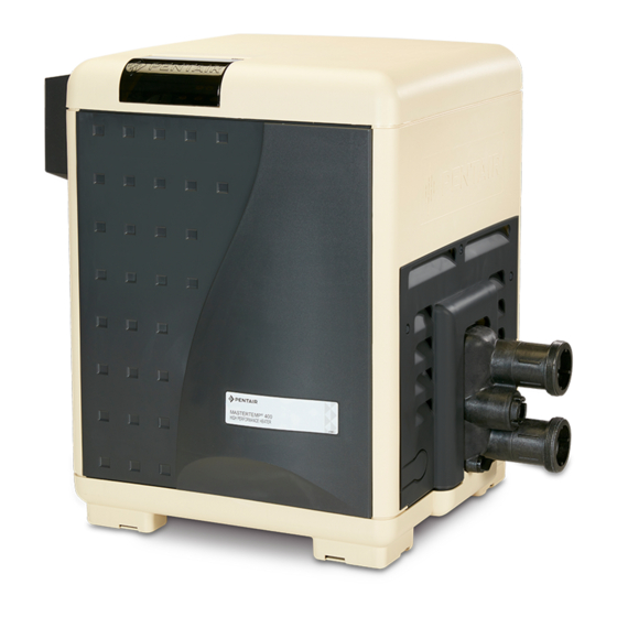
MasterTemp
POOL AND SPA HEATER
120/240 VAC NATURAL
GAS/LP GAS
I N S T A L L A T I O N
a n d
U S E R ' S G U I D E
MODELS
200K BTU/HR
250K BTU/HR
300K BTU/HR
400K BTU/HR
SPECIAL INSTRUCTIONS TO OWNER
Retain this manual for future reference.
This manual supplies information for the installation, operation,
and servicing of the appliance. READ AND REVIEW THIS
MANUAL COMPLETELY before proceeding with an installation.
Its use will reduce service calls and chance of injury and will
lengthen product life.
If the information in these instructions is not followed exactly, a fire
or explosion may result causing property damage, personal injury or death.
Call (800) 831-7133 for additional free copies of these instructions.
FOR YOUR SAFETY
Do not store or use gasoline or other flammable vapors and liquids in the vicinity of this or
any other appliance.
WHAT TO DO IF YOU SMELL GAS
• Do not try to light any appliance.
• Do not touch any electrical switch; do not use any phone in your building.
• Immediately call your gas supplier from a neighbor's phone. Follow the gas supplier's
instructions.
• If you cannot reach your gas supplier, call the fire department.
Installation and service must be performed by a qualified installer, service agency or the gas
supplier.
472592 Rev. A (04/04/06)
Natural
Propane
460730
460731
460732
460733
460734
460735
460736
460737
IMPORTANT SAFETY INSTRUCTIONS
READ AND FOLLOW ALL INSTRUCTIONS
SAVE THESE INSTRUCTIONS
WARNING
TM
®
C E R T I F I E D
®
Advertisement
Table of Contents
Troubleshooting

Related Manuals for Pentair Pool Products 200K BTU/HR


Summary of Contents for Pentair Pool Products 200K BTU/HR
- Page 1 GAS/LP GAS I N S T A L L A T I O N a n d U S E R ’ S G U I D E MODELS Natural 200K BTU/HR 460730 250K BTU/HR 460732 300K BTU/HR 460734 400K BTU/HR...
-
Page 2: Table Of Contents
INSTALLATION, OPERATION AND SERVICE MANUAL TO INSTALLER: Affix these instructions adjacent to the heater. TO CONSUMER: Retain these instructions for future reference. FOR YOUR SAFETY - This product must be installed and serviced by a professional service technician, qualified in pool heater installation. Improper installation and/or operation could create carbon monoxide gas and flue gases which could cause serious injury or death. -
Page 3: General Specifications, Requirements
Any additions, changes, or conversions required in order for the appliance to satisfactorily meet the application needs must be made by a Pentair dealer or other qualified agency using factory specified and approved parts. The heater is available for use with natural gas or LP (propane) gas only. -
Page 4: Description Of The Heater
The heater may not be installed within five feet of the inside surface of a pool or spa unless it is separated by a solid fence, wall or other permanent barrier. A Propane (LPG) fired heater must not be installed in a garage in Massachusetts, by order of the Massachusetts State Fire Marshall. -
Page 5: Spa Temperature Caution
C. Use only your hand to turn the gas control on or off. Never use tools. If you cannot change the ON/OFF setting by hand, don’t try to repair it, call a qualified service technician. Force or attempted repair may result in fire or explosion. -
Page 6: To Switch Off Gas To The Appliance
8. Push the toggle switch away from you to switch the gas on. 9. Replace the Door Access Panels. All panels must be in place when operating the heater. 10. Set 3-way valves on inlet and outlet to pool or spa, as appropriate. -
Page 7: After Start-Up
The SERVICE SYSTEM light indicates that there is insufficient water flow to the heater. If the pump is oper- ating, this usually indicates that the filter and/or skim- mers should be cleaned (some filters may require back- washing). If the light remains on after the filter/skimmers have been serviced, the system should be checked by a qualified service technician. -
Page 8: Care/Maintenance/Winterizing
CARE AND MAINTENANCE MAINTENANCE INSTRUCTIONS Risk of fire or explosion from flammable WARNING vapors. Do not store gasoline, cleaning fluids, varnishes, paints, or other volatile flammable liquids near heater or in the same room with heater. The following maintenance is recommended every six months and at the start of every swimming season: 1. -
Page 9: Outdoor Installation
OUTDOOR INSTALLATION INSTRUCTIONS For heaters located outdoors, using the built-in stackless venting system. Risk of explosion if a unit burning propane WARNING gas is installed in a pit or other low spot. Propane is heav- ier than air. Do not install the heater using propane in pits or other locations where gas might collect. -
Page 10: Outdoor Shelter/Indoor Installation
CONTROL PANEL INDEXING The exhaust discharges vertically from outside the vent cover. The heater control panel assembly located on the top panel can be rotated to any of three positions for convenient access to the panel as follows: 1. Remove the bolts from the door panels. Remove both door panels. - Page 11 NOTICE: Combustion air contaminated by corrosive chemical fumes can damage the heater and will void the warranty (See Table 1 below). HEATER CLEARANCES – OUTDOOR SHELTER (Canada) or INDOOR (U.S.) The following clearances must be maintained from com- bustible surfaces: TOP...3 ft.
- Page 12 OUTSIDE VENT COVER REMOVAL The heater is supplied from the factory with a built-in stackless outside vent for outdoor installation. Remove the outside vent cover for outdoor shelter installation. VERTICAL VENTING - NEGATIVE PRESSURE (See Figures 11 and 12) Vent the heater vertically in a negative pressure (positive draft) system in accordance with the National Fuel Gas Code, ANSI Z223.1/NFPA 54 and/or CSA B149.1, Natural Gas and Propane Installation Codes,...
- Page 13 5. Use Listed firestop for floor and ceiling penetrations. Use Listed thimble for wall penetrations. Use a Listed roof flashing, roof jack, or roof thimble for all roof penetrations. Do not fill the space around the vent (that is, the clear air space in the thimble or firestop) with insulation.
- Page 14 Table 4: Vent Termination Height vs. Roof Pitch – U.S. Roof Pitch Flat to 6/12 6/12 to 7/12 >7/12 to 8/12 >8/12 to 9/12 >9/12 to 10/12 >10/12 to 11/12 >11/12 to 12/12 >12/12 to 14/12 >14/12 to 16/12 >16/12 to 18/12 >18/12 to 20/12 >20/12 to 21/12 * Vent must be at least eight (8) feet away from nearest vertical...
-
Page 15: Water Connections
4' Min. 4' Min. Vent Vent Termination Termination 4' Min. 4' Min. 1' Minimum Gas Meter above snow or Forced Air finished grade Inlet 3' Minimum clearance if (whichever is horizontal distance to higher) exhaust opening is less than 10 feet. FIGURE 13: U.S. - Page 16 Install a check valve to prevent back-siphoning through the heater when the pump is off. NOTICE: Improper operation of chemical feeders can cause severe damage to the heater which is not covered by the warranty. Install the chemical feeder downstream of the heater (see “Water Chemistry,”...
- Page 17 Warm water out 1. Set Manual Bypass Valve 2. Remove handle FIGURE 16: Manual bypass valve Verify proper operation of the water pressure switch at the start of every season and every six months thereafter by the following steps: 1. Lower the thermostat setting to turn off the heater. 2.
-
Page 18: Pressure Relief Valve
PRESSURE RELIEF VALVE Canadian code requires and some U.S. local codes may require installation of a pressure relief valve. Purchase separately and install a 3/4" pressure relief valve comply- ing with the ANSI/ASME Boiler and Pressure Vessel Code, having a capacity equal to the Btu/hr rating of the heater. The relief pressure of the valve MUST NOT EXCEED 50 PSI. -
Page 19: Checking Combination Gas Control Valve
Instructions For Checking the Gas Pressure Through the Combination Gas Control Valve WARNING Risk of fire and explosion. Improper installation, adjustment, alteration, service, or main- tenance of the Combination Gas Control Valve can lead to fire or explosion, causing loss of life, per- sonal injury, or property damage. -
Page 20: Gas Connections
GAS CONNECTIONS The heater requires a gas supply of not less than 4" (10.2cm) wc and not more than 14" (35.6cm) wc. Gas supply pressures outside of this range may result in improper burner operation. A minimum flowing or dynamic inlet pressure of 4" (10.2cm) wc is required to maintain input rating. - Page 21 Connect the L1 of the power supply to the black wire, the L2 or neutral lead to the red wire, and the ground wire to the green wire. A time clock controlling the filter pump should have a low-voltage Fireman’s Switch that switches off the heater at least 15 minutes before shutting off the pump.
- Page 22 6. Reinstall the access door panels. The fuse for the Fireman’s Switch is a 1.25 amp 1-1/4x1/4" fast blow fuse, available locally. MAXIMUM TEMPERATURE SET POINT 1. Unbolt and remove the Door Panels (see Figure 3, Page 5). 2. Access the control panel board on the underside of the top cover.
-
Page 23: Troubleshooting
Initial Troubleshooting Only qualified, trained service technicians with appropriate test equipment should service the heater. Remember that all parts of the system affect heater operation. Before starting this troubleshooting procedure, make sure that the pump is running correctly, that there are no blockages in the system, that the valves are correctly set and that the time clock is correctly set and is running. - Page 24 Heater Will Not Fire - A Start Is green “SPA” or “POOL” LED “on” Check that correct 12-pin plug is installed (red is 240V, black is 120V) If plug is not installed: Install correct plug. 240V plug in 120V circuit: Replace with correct plug.
- Page 25 Heater Will Not Fire - B Start Is red “SERVICE HEATER” LED “on” CONTINUE Is red “SERVICE SYSTEM” LED on? Verify that pump is on, filter is not blocked, and the water flow is above the minimum requirement. With pump running, adjust Water Pressure Switch to lower pressure until ‘SER- VICE SYSTEM”...
-
Page 26: Troubleshooting
Heater Will Not Fire - C Start Is “SERVICE HEATER” LED “on”? If any red diagnostic LED’s (AGS, AFS, SFS, HLS, PS, or THERMISTOR) come “on”, go to to Pages 28 and 29. CONTINUE Did burner fire at all? Go to “BURNER TROUBLESHOOTING”... - Page 27 Heater Will Not Fire - D IMPORTANT! READ ME FIRST!! IMPORTANT! READ ME FIRST!! If your heater is correctly connected to 240 Volts AC, The Ignition Control Module (ICM) will convert the 240VAC to an intermittent pulse to the ignitor. Digital meters don’t read this type of signal well.
-
Page 28: Diagnostic Led’s
Diagnostic LED’s: AGS, AFS, HLS, PS, THERMISTOR AGS or HLS “on” Replace High Limit Switch (HLS) or Automatic Gas Shutoff (AGS) CONTINUE If problem persists, verify proper operation of Internal Bypass Valve and Thermal Governor, and check for Heat Exchanger blockage. PS “on”... -
Page 29: Sfs Diagnostic Led’s
Diagnostic LED’s: SFS SFS “on” Heater starts and runs OK, but temperature of exhaust climbs to 450º–500º in 3–5 minutes. Heater starts after several tries, exhaust temperature stays below 250º. Heater doesn’t start at all (exhaust stays cold). Check pressure and volume of fuel supply Disconnect the sensor and check continuity across its... - Page 30 Burner Troubleshooting SYMPTOM Loud, high-pitched whine Flame is “fluttery.” Exhaust may have acrid smell or burner may fail to stay lit. Burner pulsates or surges, especially on ignition. Combustion appears normal, but flame does not stay lit. Heat Exchanger Troubleshooting SYMPTOM Boiling in heat exchanger.
-
Page 31: Repair Parts
For complete Water System parts breakdown (Key Nos. 10 through 13), see Page 34 Repair Parts are available from your Pentair dealer. If your dealer cannot supply you, call Customer Support at 1-800-831-7133. For complete Burner System parts breakdown (Key Nos. 5 through 9),... - Page 32 For Heater mounting bolts and clamps, purchase separately Bolt Down Bracket Kit, Part No. 460738.
- Page 33 REPAIR PARTS – BURNER SYSTEM Part Description Combination Gas Control Valve Kit 3/4" Union Gas Orifice • Gas Orifice Kit – NG (Incl. Key Nos. 3 and 4)† • Gas Orifice Kit – Propane (Incl. Key Nos. 3 and 4)† •...
- Page 34 REPAIR PARTS – WATER SYSTEM Part Description Tube Sheet Coil Assembly Kit (NA, LP Series) (Includes Key No.3) Manifold Kit (Includes Key Nos. 3-14, 21, and Key Nos. 7-9 in “Electrical System”, Page 35 Coil/Tubesheet Sealing O-Ring Kit Manifold Bottom Plate Manifold O-Ring •...
-
Page 35: Repair Parts
REPAIR PARTS – ELECTRICAL SYSTEM Part Description Heater Display Cover Igniter Bracket Igniter/Igniter Gasket Kit Incl. Key Nos. 4 and 5) Igniter Gasket Automatic Gas Shutoff Switch (AGS) High Limit Switch Thermistor Terminal Board Fireman’s Switch Fuse (1.25A, 1-1/4") Ignition Control Module Transformer, 115/230V Air Flow Switch Control Board Kit (NA, LP Series) -
Page 36: Wiring Diagrams/External Control Interface
Pool Heater Wiring Connection Diagram AGS Switch Stack Flue Sensor Gas Valve External Control Interface Circuit Disabled, Heater Membrane Pad Enabled External Control Interface External Control Interface Circuit Enabled, "Pool On" and "Spa On" Keys Disabled. "OFF" Key on Membrane Pad Remains Functional. Plug –12 pin 120V –... - Page 37 Pool Heater Electrical Schematic Ladder Diagram 24 VAC COM NO SWITCH THERMISTOR SENSOR NOTES: ARE CONNECTED ON THE IGNITION MODULE. 2. ) PIN AND SOCKET CONNECTOR. 3. ) IF ANY OF THE ORIGINAL WIRES AS SUPPLIED WITH THE APPLIANCE MUST BE REPLACED, THEY MUST BE REPLACED WITH TYPE 105C OR ITS EQUIVALENT.
-
Page 38: Save These Instructions
Trademarks and disclaimers: MasterTemp and the Pentair Pool Products and Pentair Water Pool and Spa logos are trade- marks of Pentair Water Pool and Spa, Inc. Other trademarks and trade names may be used in this document to refer to either the entities claiming the marks and names or their products.