Makita 6936FD Technical Information
Hide thumbs
Also See for 6936FD:
- Instruction manual (49 pages) ,
- Parts breakdown (2 pages) ,
- Instruction manual (12 pages)
Advertisement
Quick Links
Download this manual
See also:
Instruction Manual
T
ECHNICAL INFORMATION
Models No.
Description
C
ONCEPT AND MAIN APPLICATIONS
Model 6936FD has been developed as an 18V version tool of the
current 14.4V Model 6935FD.
Uses 18V cluster type batteries as power source, and features the following
same benefits as Model 6935FD.
With built-in LED job light
Hammer case of new design without screw hole protrusions
for increased maneuverability
Phosphorescent (glow-in-the-dark) bumper
Max. fastening torque: 140 N.m
This new product will be available in the following variations.
Model No.
6936FDWAE
6936FDWDE*
6936FDWFE
6936FDZ
*Offered as Model 6936FD to USA, Canada, Mexico, and Panama
S
pecification
Voltage: V
Battery
Capacity: Ah
Cell
Max output: W
Driving shank
Capacities
Impacts per min.: min.-1=bpm
No load speed: min.-
Max. fastening torque: N.m (kgf.cm/in.lbs)
Electric brake
Variable speed (electric)
Reversing switch
Net weight*: kg (lbs)
*Net weight includes battery.
S
tandard equipment
Battery cover ......................... 2 pcs
Plastic carrying case ............. 1 pc
Hook ..................................... 1 pc
Note: The standard equipment for the tool shown may differ by country.
O
ptional accessories
Assorted socket bits
Assorted Phillips bits
Stopper for impact driver
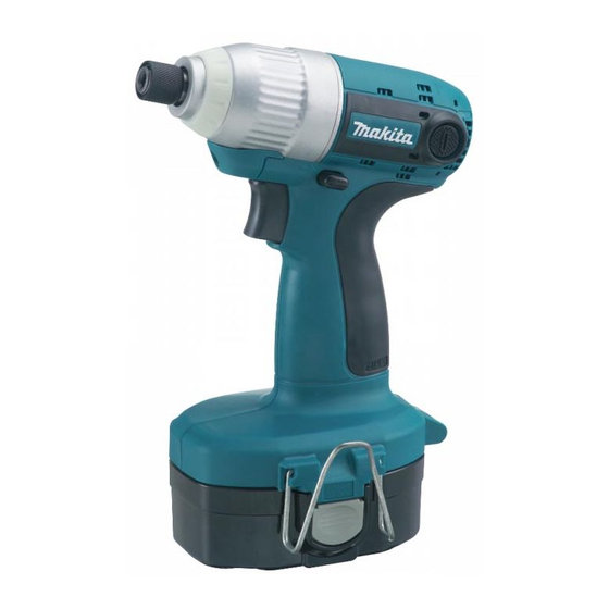
6936FD
Cordless Impact Driver
Battery
type
1822 (2.0Ah/ Ni-Cd)
1834 (2.6Ah/ Ni-MH)
1835 (3.0Ah/ Ni-MH)
No
Machine screw
Standard bolt
High tensile bolt
Coarse thread screw
=rpm
1
Battery 1822 (2.0Ah/ Ni-Cd)
Battery 1834 (2.6Ah/ Ni-MH)
Battery 1835 (3.0Ah/ Ni-MH)
Battery PA18 (1.3Ah/ Ni-Cd)
Charger
quantity
carrying case
2
DC1804
No
2.0/ 2.6/ 3.0
Ni-Cd/ Ni-MH
6.35mm (1/4") Hex
M4 - M8 (5/32 - 5/16")
M5 - M14 (3/16 - 9/16")
M5 - M12 (3/16 - 15/32")
22 - 125mm (7/8 - 4-7/8")
0 - 3,200
0 - 2,600
140 (1,430/ 1,240)
1.9 (4.2)
Charger DC1804
Automotive charger DC1822
W
Plastic
Dimensions: mm ( " )
Length ( L )
Width ( W )
Yes
Height ( H )
No
18
250
Yes
Yes
Yes
PRODUCT
P 1 / 8
L
H
163 (6-3/8)
94 (3-11/16)
243 (9-9/16)
Advertisement

Related Manuals for Makita 6936FD


Summary of Contents for Makita 6936FD
- Page 1 Description Cordless Impact Driver ONCEPT AND MAIN APPLICATIONS Model 6936FD has been developed as an 18V version tool of the current 14.4V Model 6935FD. Uses 18V cluster type batteries as power source, and features the following same benefits as Model 6935FD.
-
Page 2: Necessary Repairing Tools
Modular use with No.1R045 134847-1 Socket 30-78 Modular use with No.1R223 [2] LUBRICATION Apply Makita grease N. No.2 to the following portions designated with the black triangle to protect parts and product from unusual abrasion. Item No. Description Portion to lubricate... - Page 3 P 3 / 8 epair [3] DISASSEMBLY/ASSEMBLY [3] -1. Bit Holder Section Fig. 2 DISASSEMBLING See Fig. 2. Ring spring 11 Steel ball 3.5 (2pcs) 1) Remove Ring spring 11 from the groove on Anvil M using Retaining ring S and R pliers (No.1R291). groove Flat washer 12 2) Now the following parts can be removed from Anvil M:...
- Page 4 P 4 / 8 epair [3] -2. Hammer Case Complete (cont.) ASSEMBLING Do the reverse of the disassembling steps. Note 1: Do not forget to put O ring 46 in the groove on Internal gear case. (Fig. 5) Note 2: When fastening Gear case complete to Internal gear case, turning Gear case complete counterclockwise to the recommended torque of 30 - 40N.m.
- Page 5 P 5 / 8 epair [3] -3. Housing L/Housing R and Motor Section (cont.) DISASSEMBLING 5) Remove the Motor section from Housing L. Then remove Endbell complete from Armature. (Fig. 10) 6) Put the Motor section on a work bench so that the drive end of Armature touches the work bench. Then separate yoke unit from armature by pulling it down towards the work bench.
- Page 6 P 6 / 8 epair [3] -3. Housing L/Housing R and Motor Section (cont.) ASSEMBLING 4) Assemble F/R Change lever to switch unit with the projection Fig. 16 on Switch unit fit in the loop portion of F/R Change lever. loop portion (Fig.
- Page 7 P 7 / 8 epair [3] -4. Hammer Mechanism and Spindle Section (cont.) DISASSEMBLING 5) Now Hammer mechanism can be disassembled as illustrated in Fig. 19. 6) After removal of Flat washer 24, twenty-four 3.5 Steel balls can be removed from Hammer. (Fig. 20) Fig.
-
Page 8: Circuit Diagram
P 8 / 8 ircuit diagram Endbell Color index of lead wires' sheath Black White (Field Effect Transistor) LED circuit section of Switch Switch iring diagram 1) Before Installation of Internal Electric Parts Place the slack of LED lead wires here. LED circuit section of Switch Boss...