Table of Contents
Advertisement
Quick Links
Advertisement
Table of Contents

Related Manuals for Leica mojo3D


Summary of Contents for Leica mojo3D
-
Page 1: User Manual
Leica mojo3D User Manual Version 1.1 English... - Page 2 The type and serial number of your product are indicated on the type plate. Enter the tion type and serial number in your manual and always refer to this information when you need to contact your agency or Leica Geosystems authorised service workshop. Type: _______________ Serial No.:...
- Page 3 Important paragraphs which must be adhered to in practice as they enable the product to be used in a technically correct and efficient manner. Trademarks All other trademarks are the property of their respective owners. Leica mojo3D, Introduction...
-
Page 4: Table Of Contents
Hardware 1.3.2 mojo3D Software 1.3.3 mojo3D Positioning 1.3.4 mojo3D Guidance 1.3.5 mojo3D Section Control and Mapping System Installation Before Installation mojo3D Installation Antenna Installation SIM Card Installation Running the mojo3D for the First Time Starting Up Setting the Screen Calibration... - Page 5 Setting Guidance Types AB Parallel Guidance A+ Heading Guidance Fixed Contour Guidance Pivot Guidance Guidance Management 4.5.1 Saving a Wayline 4.5.2 Changing the Name of a Wayline 4.5.3 Deleting an Individual Wayline 4.5.4 Deleting All Waylines Leica mojo3D, Table of Contents...
-
Page 6: Leica Mojo3D, Table Of Contents
Leica mojo3D, Table of Contents 4.5.5 Exporting Guidelines 4.5.6 Importing Guidelines Field Offset Nudge Auto-Steer Engage Auto-Steer Tuning Auto-Steer Performance 5.2.1 Tuning Procedure 5.2.2 Sensitivity 5.2.3 Aggressiveness 5.2.4 Overshoot 5.2.5 Speed Adjust 5.2.6 Tuning Tips Treatments Starting a New Treatment 6.1.1... - Page 7 Virtual Wrench™ Remote Service Virtual Wrench™ Making a Service Request Upgrading Software from Virtual Wrench™ Upgrading Software via USB Flash Drive Restoring Previous Software Version Backing Up Current Software Serial Numbers and Other System Information Leica mojo3D, Table of Contents...
-
Page 8: Leica Mojo3D, Table Of Contents
Leica mojo3D, Table of Contents 10 Care and Transport 10.1 Transport 10.2 Storage 10.3 Cleaning and Drying 11 Safety Directions 11.1 General Introduction 11.2 Intended Use 11.3 Limits of Use 11.4 Responsibilities 11.5 Hazards of Use 11.6 Electromagnetic Compatibility (EMC) 11.7 FCC Statement, Applicable in U.S. - Page 9 12.5 Conformity to National Regulations 13 International Limited Warranty, Software License Agreement Appendix A mojo3D Enhancements mojo3D with Single Section Control mojo3D with Multi Section Control Kit mojo3D with Electric Auto-Steer Kit mojo3D with mojoRTK Kit Appendix B Formatting USB Flash Drives...
-
Page 10: System Overview
• Beyond its capabilities of visual or auto steer guidance and section control the mojo3D also provides remote service and diagnostics and remote upgrades via Virtual Wrench, thus reducing costly on-site service calls. -
Page 11: Components Of The Mojo3D System
Components of the mojo3D System mojo3D compo- nents a) RAM mount - ball b) RAM mount - arm c) mojo3D display d) Glass-mount cell modem antenna e) Magnetic-mount GPS antenna GPS antenna mounting kit g) Standard power cable h) Product documentation... - Page 12 Leica mojo3D, System Overview Refer to "Appendix A mojo3D Enhancements" for more information about the acces- sory options, their installation and use.
-
Page 13: Features And Specifications
Simple installation, with RAM mount and colour-coded quick-install antennas • Integrated L1 GPS receiver • Integrated cell modem, CDMA or HSDPA depending on region ordered • 12 volt operation • Internal storage for waylines, worked areas, and settings Leica mojo3D, System Overview... - Page 14 Leica mojo3D, System Overview Caution Operation by touch screen: The mojo3D is designed to be used by a finger tapping the display screen. It may affect warranty if operated with a hard object i.e. stylus or pen...
-
Page 15: Mojo3D Software
Optional Radar-out signal for auxiliary devices that require a radar speed signal. • Leica Twist compatible for terrain compensated electric auto steer. • Leica mojoRTK Console compatible for base station RTK, Network RTK, and Dual Frequency Glide. Leica mojo3D, System Overview... -
Page 16: Mojo3D Guidance
View in 3D perspective, with heads-up, chase, top-down, and north-up modes. • On-screen lightbar with heading assist operation. • Electric auto-steer capable, with Electric Steer Kit. • Hydraulic auto-steer capable, with Leica mojoRTK Console. 1.3.5 mojo3D Section Control and Mapping mojo3D section • Single-section control using port expansion cable control and •... - Page 17 Leica mojo3D, System Overview...
-
Page 18: System Installation
The installer must be able to use the system in accordance with the user manual. However, Leica Geosystems recommends that installation of the mojo3D equipment be performed by a qualified technician, because instal- lation requires making electrical connections. •... - Page 19 • The average installation time will vary, but it should be approximately two to four hours per vehicle. The time of installation may be more or less, based on vehicle type and options purchased. Leica mojo3D, System Installation...
-
Page 20: Mojo3D Installation
Leica mojo3D, System Installation mojo3D Installation RAM mount and Select an appropriate place to mount the mojo3D display. mojo3D display The display needs to be within easy reach of the operator when seated in installation the normal operating position, and ideally it will be easily visible in the forward field of vision of the operator. - Page 21 Warning Do not mount the mojo3D where it may obscure the driver’s view of the road or field. Warning Do not mount the mojo3D where it may be struck by a deploying airbag. Power cable instal- 1. Connect the supplied power cable to a reliable power source, for example, the lation vehicle’s main power system.
- Page 22 Master input The optional master input on the mojo3D power cable may be connected to an external switch for remote operation of the Master Record Status button which starts and stops coverage recording on screen.
-
Page 23: Antenna Installation
® cleaning products are denatured alcohol and Windex glass cleaner. mojo3D GPS The mojo3D GPS antenna should be mounted on the vehicle roof: antenna • on the centre line of the implement, which may not necessarily be the centre of the vehicles roof •... - Page 24 The antenna must be mounted horizontally and not on an angle to ensure best GPS reception possible. • If the mojo3D is to be connected to a Leica mojoRTK, the mojo3D GPS antenna is not required, however the cell modem antenna is still required.
- Page 25 The mojo3D cell radio antenna can be mojo3D cell radio mounted directly on the inside of the vehicle antenna cabin glass, 5 c m • at least 5 cm (2") from the surrounding metal frame. • no closer than 20 cm (8") to the oper- ator's normal driving position.
- Page 26 System performance may fail or be degraded if cables are cut, kinked or unduly bent • Cables should be routed neatly back to the mojo3D. The antenna adhesive backing is very strong. If unsure of the mounting position and removal may be required only peel back a small amount of backing tape.
-
Page 27: Sim Card Installation
SIM Card Installation To enable Virtual Wrench™ on systems equipped with a HSDPA internal modem a SIM Card from a suitable service provider is required. 1. Place mojo3D face down on a work- bench. 2. Remove the two screws and open the cover for the SIM card slot. - Page 28 When the mojo3D is turned on the cell phone icon should appear with signal strength. Caution The mojo3D must remain face down on a workbench when inserting a SIM card to remove the possibility of the SIM card being dropped inside the mojo3D.
- Page 29 Leica mojo3D, System Installation...
-
Page 30: Running The Mojo3D For The First Time
Leica mojo3D, Running the mojo3D for the First Time Running the mojo3D for the First Time Starting Up power button Starting up, 1. To start the mojo3D, press and hold the for two seconds. step-by-step 2. The splash screen appears on the mojo3D display, and is... -
Page 31: Setting The Screen Calibration
If required Screen Calibration can be updated anytime while the mojo3D is powered on by holding the power button for 8 seconds, release the power button to display the screen calibration screen. -
Page 32: Initial Setup Wizard
Leica mojo3D, Running the mojo3D for the First Time Initial Setup Wizard General informa- • The language used in displays, screen brightness, country, units of length, speed, tion and display mode must be set. • The brightness screen is the first initial setup screen to appear. - Page 33 • display mode: day mode, night mode, or automatic switch between modes. 2. After making your selections, tap to continue. Leica mojo3D, Running the mojo3D for the First Time...
- Page 34 Leica mojo3D, Running the mojo3D for the First Time Cell modem setup, The information required for cell modem setup is available from your cellular network step-by-step provider. Depending on the region purchased, this information may be pre-selected. If this is the case, this screen will not be displayed.
- Page 35 1. On the Vehicle setup screen, tap the vehicle type in the list at the left of the step-by-step screen. Tap to reveal more options. 2. Enter the measurements required for the vehicle type that you have selected. • Tap on a field. The on-screen keyboard appears. Leica mojo3D, Running the mojo3D for the First Time...
- Page 36 Leica mojo3D, Running the mojo3D for the First Time • Use the on-screen keyboard to enter the measurement, tap to continue. • Repeat for the other measurements required. 3. After you have entered all required vehicle measurements, add any required implements on the same screen.
- Page 37 • Single Section: a maximum of one section can be setup for the vehicle. This section is automatically controlled with physical output on the port expansion cable. • Leica AS400: multiple sections are automatically controlled via the Leica AS400 section controller hardware, supplied with the multi-section control kit 2. Tap to select implement mode: •...
- Page 38 Master Record button on the screen. • mojo3D / Master Input: the on screen coverage mapping is activated by sensing a voltage connected to the Master wire on the mojo3D power cable. • Leica AS400 / Single: the on screen coverage mapping is activated by sensing a voltage connected to the Master wire on the Leica AS400 controller port.
- Page 39 • Off latency: the number of seconds it takes from the section being turned off until the actual application stops. • On latency: the number of seconds it takes from the section being turned on until the actual application starts. Leica mojo3D, Running the mojo3D for the First Time...
- Page 40 (button at bottom left of screen) 2. Tap to continue. • If the mojo3D option was selected the NMEA configuration screen appears. • If another option was selected, then the configuration setup for the selected device will be displayed. Refer to "Appendix A mojo3D Enhancements" for more information on...
- Page 41 NMEA configura- If NMEA output is not required tap to complete the initial setup. tion If NMEA output is required from the mojo3D, follow the detailed informa- tion in "8 NMEA Output". Leica mojo3D, Running the mojo3D for the First Time...
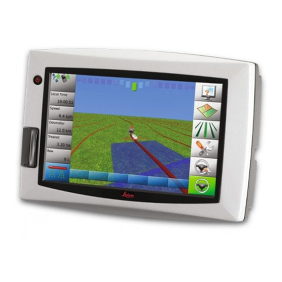
- Page 42 Leica mojo3D, Running the mojo3D for the First Time Main navigation Once the Initial Setup Wizard is complete the main navigation screen will be screen displayed: Primarily status information is The buttons down the right hand side of displayed on the left hand side.
-
Page 43: Menu Buttons At Right Of Screen
An example of a flyout menu is shown on Guidance page 44. Settings Auto-steer If the mojo3D is being used without Settings additional auto-steer options, then the Auto-steer Settings button and the Auto-steer button will be disa- Auto-steer bled. Leica mojo3D, Running the mojo3D for the First Time... - Page 44 Leica mojo3D, Running the mojo3D for the First Time Flyout Menu Example...
-
Page 45: Menu Buttons At Left Of Screen
• Base station (if used) • Satellites visible • Cell modem signal strength Five buttons with • Virtual Wrench™ (if connected) user-selected data. Refer to see "3.9 Error Notifications" for more information. Master record status Leica mojo3D, Running the mojo3D for the First Time... -
Page 46: Specifying Data For Display
Leica mojo3D, Running the mojo3D for the First Time Specifying Data for Display Specifying data for The items displayed at the left of the main navigation screen may be selected by the display, user. To specify the items for display, carry out the following steps: step-by-step 1. - Page 47 3. To set the odometer display to zero, tap the reset odometer button at the right of the screen. 4. Tap to return to the main navigation screen. Leica mojo3D, Running the mojo3D for the First Time...
-
Page 48: Zoom Buttons
Leica mojo3D, Running the mojo3D for the First Time Zoom Buttons Using zoom To use the zoom buttons, carry out the following steps: buttons, step-by- • To display the zoom buttons, touch the middle of the screen, the zoom buttons step will appear on the main navigation screen. - Page 49 1. Touch the middle of the screen, to display the zoom buttons. 2. Tap either repeatedly, until the view mode changes. To change between Top Down North Up and Top Down Heads Up refer to "3.11 Changing System Settings". Leica mojo3D, Running the mojo3D for the First Time...
-
Page 50: Error Notifications
Leica mojo3D, Running the mojo3D for the First Time Error Notifications When a new error occurs the status button will show an active error General informa- icon. To view information about the error tap the button. tion At any time the complete list of recent errors can be viewed. -
Page 51: Running The Setup Wizard At Any Time
Make any changes that are required. For specific information on the different settings refer to "3.3 Initial Setup Wizard". All changes are automatically saved as they are made. Leica mojo3D, Running the mojo3D for the First Time... -
Page 52: Changing System Settings
Leica mojo3D, Running the mojo3D for the First Time 3.11 Changing System Settings General informa- The system settings includes: tion • Screen brightness • Measure units (length, speed & area) • Country • Top down mode • Language • Display (day/night) mode •... -
Page 53: Vehicle Setup
Make any changes that are required. For specific information on the different settings refer to "3.3 Initial Setup Wizard". All changes are automatically saved as they are made. Leica mojo3D, Running the mojo3D for the First Time... -
Page 54: Attached Device Selection
Leica mojo3D, Running the mojo3D for the First Time 3.13 Attached Device Selection General informa- Attached device selection includes: tion • Selection of attached device: • None (mojo3D is used as a standalone device) • Electric Steer Kit • Leica mojoRTK •... - Page 55 Refer to "Appendix A mojo3D Enhancements" for more information on these setups. All changes are automatically saved as they are made. Leica mojo3D, Running the mojo3D for the First Time...
-
Page 56: Nmea Configuration
Leica mojo3D, Running the mojo3D for the First Time 3.14 NMEA Configuration General informa- NMEA configuration includes: tion • Configure serial port & NMEA messages • Log NMEA to USB • Advanced NMEA configuration NMEA configura- To select and change one of these items, carry out the following steps: tion, step-by-step 1. -
Page 57: Feature Unlock
3. To activate a new feature, tap the Enter New Code button. Use the on-screen keyboard to enter the new code. 4. Tap to save settings and return to the main navigation screen. Leica mojo3D, Running the mojo3D for the First Time... -
Page 58: Setting Guidance Types
Leica mojo3D, Setting Guidance Types Setting Guidance Types Waypoints Waypoints are used to define a line in the field to which all working lines will be parallel. Waypoints must be set before auto-steer can be used. AB Parallel Guidance In AB Parallel guidance, working lines are parallel,... - Page 59 5. On the dialog box that appears: • tap to save the wayline to memory. An on-screen keyboard appears. Enter a name for the wayline, and tap • tap to use the wayline without first saving it to memory. Leica mojo3D, Setting Guidance Types...
-
Page 60: A+ Heading Guidance
Leica mojo3D, Setting Guidance Types A+ Heading Guidance In A+ heading guidance, working lines are parallel, General informa- and are set by defining an initial waypoint and a tion compass bearing. Before you can set waypoints, the system must have a good position fix. - Page 61 5. On the dialog box that appears: • tap to save the wayline to memory. An on-screen keyboard appears. Enter a name for the wayline, and tap • tap to use the wayline without first saving it to memory. Leica mojo3D, Setting Guidance Types...
-
Page 62: Fixed Contour Guidance
Leica mojo3D, Setting Guidance Types Fixed Contour Guidance In fixed contour guidance, working lines are parallel General informa- curves, and are set by defining an initial contour tion with a beginning and an ending waypoint. Before you can set waypoints, the system must have a good position fix. - Page 63 6. On the dialog box that appears: • tap to save the wayline to memory. An on-screen keyboard appears. Enter a name for the wayline, and tap • tap to use the wayline without first saving it to memory. Leica mojo3D, Setting Guidance Types...
-
Page 64: Pivot Guidance
Leica mojo3D, Setting Guidance Types Pivot Guidance In pivot guidance, working lines are concentric General informa- circles and are defined by setting three waypoints. tion Before you can set waypoints, the system must have a good position fix. Setting pivot guid-... - Page 65 6. On the dialog box that appears: • tap to save the wayline. An on-screen keyboard appears. Enter a name for the wayline, and tap • tap to use the wayline without first saving it to memory. Leica mojo3D, Setting Guidance Types...
-
Page 66: Guidance Management
Leica mojo3D, Setting Guidance Types Guidance Management 4.5.1 Saving a Wayline Automatic saving Every time a wayline is set a dialog box is displayed which allows the line to be imme- diately saved by tapping . The line can be used without first saving by tapping... -
Page 67: Changing The Name Of A Wayline
4.5.2 Changing the Name of a Wayline General informa- The name under which a wayline is stored on the mojo3D can be changed. The actual tion data in the wayline cannot be changed, only deleted. Changing wayline To change the name of a stored wayline, carry out the following steps: name, step-by- 1. -
Page 68: Deleting An Individual Wayline
4.5.3 Deleting an Individual Wayline General informa- A wayline stored on the mojo3D can be deleted. Once a wayline has been deleted, it tion cannot be recovered, unless it has been backed up to a USB Flash Drive before. Deleting a wayline,... -
Page 69: Deleting All Waylines
4.5.4 Deleting All Waylines General informa- All of the waylines stored on the mojo3D can be deleted simultaneously. Once the tion waylines have been deleted, they cannot be recovered, unless they have been backed up to a USB Flash Drive before. - Page 70 Leica mojo3D, Setting Guidance Types 5. Tap to return to the main navigation screen.
-
Page 71: Exporting Guidelines
Refer to "Appendix B Formatting USB Flash Drives" for important informa- tion about using USB drives with the mojo3D products. Do not turn off the mojo3D, or remove the USB Flash Drive, while the guideline export is under way. Exporting guide-... - Page 72 Leica mojo3D, Setting Guidance Types 2. On the main navigation screen, tap the settings button. 3. On the flyout menu, tap the transfer data button. 4. Tap the export to USB button and tap to continue. 5. Tap the Guidance button and tap to continue.
-
Page 73: Importing Guidelines
Refer to "Appendix B Formatting USB Flash Drives" for important informa- tion about using USB drives with the mojo3D products. Do not turn off the mojo3D, or remove the USB Flash Drive, while the guideline import is under way. Importing guide-... - Page 74 6. To select the waylines to be imported tap the wayline name to select or deselect it. All waylines can be selected by tapping the Select All button. If there are waylines with the same name already on the mojo3D a screen will be displayed to allow the conflicting waylines to be renamed.
-
Page 75: Field Offset
1. On the main navigation screen, tap the guidance button. step 2. On the flyout menu, tap the field offset button. 3. Tap the field offset value box. The on–screen number pad appears. Leica mojo3D, Setting Guidance Types... - Page 76 Leica mojo3D, Setting Guidance Types 4. Use the on–screen number pad to enter a value for the field offset. Tap the number pad when finished. 5. Tap to return to the main navigation screen.
-
Page 77: Nudge
Nudge Description The GPS system in the mojo3D is subject to drift over time. If you use the mojo3D for extended periods of time, then it may be necessary to adjust the GPS position using nudge. Nudge uses the wayline as a reference to adjust the GPS position. This can be thought of as moving all data on the screen (waylines and map data) to the position of the vehicle. -
Page 78: Auto-Steer
Leica mojo3D, Auto-Steer Auto-Steer Engage Auto-Steer Auto-steer status The auto-steer button on the main navigation screen is used to engage and disen- gage auto-steer. The colour of this button also indicates the current status of the auto-steer. • Red: Roading is active and auto-steer can not be engaged until roading is turned off. - Page 79 To enable roading, carry out the following steps: 1. On the main navigation screen, tap the steering settings button. 2. On the flyout menu, tap the roading button. 3. Roading will be enabled and the auto-steer button will turn red. Leica mojo3D, Auto-Steer...
- Page 80 Leica mojo3D, Auto-Steer Preconditions to The conditions required for auto-steer to engage will depend on the steer kit being engage auto-steer used. The following is a typical example of the conditions required to be met before automatic steering can occur: •...
- Page 81 2. The auto-steer button will turn red to indicate auto-steer is disengaged and the vehicle is no longer being automatically steered. Other methods to disengage the steering will be available and this method will depend on the steer kit used. Leica mojo3D, Auto-Steer...
-
Page 82: Tuning Auto-Steer Performance
For optimal performance, the system tuning must be refined for your steering kit/vehicle. 5.2.1 Tuning Procedure Tuning the mojo3D To adjust the tuning settings for the mojo3D steering, carry out the following steps: steering, step-by- 1. On the main navigation screen, tap the auto-steer settings step button. - Page 83 • Each setting is specified by a nominal scale from 50 to 150. • The value of the setting is adjusted by moving an on-screen slider. • The auto-steer performance is shown in the panel on the right hand side of the screen. Leica mojo3D, Auto-Steer...
- Page 84 Leica mojo3D, Auto-Steer Saving tuning data • to save all changes made to the settings, and return to the main naviga- tion screen. • to return to the main navigation screen without saving any changes made to any of the tuning parameters.
-
Page 85: Sensitivity
Sensitivity should be the only parameter that you need to adjust to adapt the control performance to the current working conditions after the tuning refinement is done. 1. On the tuning screen, tap the sensitivity button 2. Adjust the slider to vary the sensitivity, by using the Leica mojo3D, Auto-Steer... - Page 86 Leica mojo3D, Auto-Steer Explanation • The sensitivity can be set between 50% and 150%. The standard setting is 100%. • In general, higher sensitivity is for slower travelling speed, lower sensitivity for faster speed. • Different sensitivity settings and their...
-
Page 87: Aggressiveness
2. Adjust the slider to vary the aggressiveness, by using the Explanation • The aggressiveness can be set between 50% and 150%. The standard setting is 100%. • Different aggressiveness settings and their approach to the working line: 150% 100% mojoRTK_012 Leica mojo3D, Auto-Steer... -
Page 88: Overshoot
Leica mojo3D, Auto-Steer 5.2.4 Overshoot Setting the over- The overshoot value will control the rate at which the vehicle will drive at the line and shoot the rate that the vehicle will round off as it approaches the line. A low value will cause the vehicle to hold off the line longer while a high value will cause the vehicle to converge quickly and possibly drive past the line. -
Page 89: Speed Adjust
2. Adjust the slider to vary the speed adjust, by using the left and right arrows. • The speed adjust can be set between 50% and 150%. The standard value is 100%. • The speed adjust has no effect at or below 5 km/h (3 mph). Leica mojo3D, Auto-Steer... -
Page 90: Tuning Tips
Leica mojo3D, Auto-Steer 5.2.6 Tuning Tips General tuning tips When dealing with the tuning, each parameter must be treated separately, even though they may have interactions between them. When tuning for: • turning rate and twitch on the line, use Sensitivity. - Page 91 Vehicle turns very aggressively to drive toward Reduce the Sensitivity. the line and twitches when on the line. Vehicle oscillates only at higher speeds. Reduce the Speed Adjust. Vehicle does not hold the line only at higher Increase the Speed Adjust. speeds. Leica mojo3D, Auto-Steer...
-
Page 92: Treatments
Leica mojo3D, Treatments Treatments General informa- • Field treatments record the coverage activity that the user initiates by tapping tion on the master record status button. • Coverage data is added in real time to the current field treatments record. -
Page 93: Starting A New Treatment
2. On the flyout menu, tap the new treatment button. 3. On the dialog box that appears: • tap to start a new treatment. An on-screen keyboard appears. Enter a name for the treatment, and tap • tap to continue with the current treatment. Leica mojo3D, Treatments... -
Page 94: Load A Stored Treatment
Leica mojo3D, Treatments 6.1.1 Load a Stored Treatment Load a stored To load a stored treatment, carry out the following steps: treatment, step- 1. On the main navigation screen, tap the mapping button. by-step 2. On the flyout menu, tap the management button. -
Page 95: Changing A Treatment Name
2. On the flyout menu, tap the management button. 3. Tap to scroll though the list of treatments. Tap the treatment name to select it. 4. Tap the edit button. 5. Use the on-screen keyboard to change the name of the treatment, and then Leica mojo3D, Treatments... -
Page 96: Creating A Pdf Report Of A Treatment
6.1.3 Creating a PDF Report of a Treatment General informa- A PDF report of a treatment can be created directly on the mojo3D and exported to tion a USB Flash Drive. A USB Flash Drive must be inserted into the mojo3D for this action to be available. -
Page 97: Deleting A Treatment
Tap the treatment name to select it. 4. Tap the delete button. 5. On the dialog box that appears: • tap to continue with the deletion. • tap to abandon the deletion. Leica mojo3D, Treatments... -
Page 98: Exporting Treatment Data
USB drives with the mojo3D products. by-step Do not turn off the mojo3D, or remove the USB Flash Drive, while the treat- ment data export is under way. To export treatment data, carry out the following steps: 1. - Page 99 6. On the dialog box that appears: • tap to overwrite the data on the USB Flash Drive. • tap to cancel the copy operation. 7. Tap to return to the main navigation screen. Leica mojo3D, Treatments...
-
Page 100: Importing Treatment Data
USB drives with the mojo3D products. by-step Do not turn off the mojo3D, or remove the USB Flash Drive, while the treat- ment data import is under way. To import treatment data, carry out the following steps: 1. - Page 101 6. There will be a message to confirm overwriting the data. On the dialog box that appears: • tap to overwrite the data on the mojo3D with the data from the USB Flash Drive. • tap to cancel the copy operation.
-
Page 102: Automatic Section Control
Master on, but paused because of low or high speed. • Master off, coverage not recording. If mojo3D / Touch was selected as the master input source and input mode in the vehicle setup, then tapping the master record status button will turn the coverage recording on and off. -
Page 103: Section Control Latency
ON and the application physically starting. This may be a very small value - a few tenths of a second - and hard to measure accurately. Latency can be measured more accurately by measuring the distance travelled at a given speed. Leica mojo3D, Automatic Section Control... -
Page 104: Calibrating The Section Control Latency Value
Leica mojo3D, Automatic Section Control 7.1.1 Calibrating the Section Control Latency Value For the purpose of this calibration exercise, if using a boom spray, the tank should contain only water. Calibrating latency, To calibrate the section control latency value, carry out the following steps: step-by-step 1. - Page 105 Example Assuming that the operator was travelling at 20 km/h and the distance from the rope to where the application reacted is 5 m: 5 m ÷ 20 km/h x 3.6 = 0.9 seconds Latency Leica mojo3D, Automatic Section Control...
-
Page 106: Troubleshooting Latency Problems
Leica mojo3D, Automatic Section Control Imperial/US calcu- Latency [s] = Distance travelled [ft] ÷ Speed [mph] x 0.68 lation Example Assuming that the operator was travelling at 12 mph and the distance from the rope to where the application reacted is 16 ft: 16 ft ÷... - Page 107 The section is turned OFF too Decrease the OFF latency early, and a missed area results. value. The section takes too long to Increase the ON latency turn ON, and a missed area value. results. Leica mojo3D, Automatic Section Control...
- Page 108 Leica mojo3D, Automatic Section Control Problem Solution The section turns ON too early, Decrease the ON latency and an overlap results. value.
-
Page 109: Setting The Overlap Limit
If the overlap limit is decreased, the system will not turn on the application when traversing a small missed area, such as a strip between two spray swaths. 100% Leica mojo3D, Automatic Section Control... - Page 110 Leica mojo3D, Automatic Section Control Setting the overlap To set the overlap limit, carry out the following steps: limit, step-by-step 1. On the main navigation screen, tap the settings button. 2. On the flyout menu, tap the Vehicle setup button.
-
Page 111: Setting The Low-Speed Shutoff
Setting low-speed To set the low-speed shutoff, carry out the following steps: shutoff, step-by- 1. On the main navigation screen, tap the settings button. step 2. On the flyout menu, tap the Vehicle setup button. Leica mojo3D, Automatic Section Control... - Page 112 Leica mojo3D, Automatic Section Control 3. Tap several times until the Section Control Setup screen is shown. 4. Tap the Low Speed Shutoff value box. 5. Use the on–screen number pad to enter a value for the minimum speed. Tap on the number pad when finished.
-
Page 113: Section Override Control
• Off: The section is turned off, and will not apply coverage. • Auto: Auto section control will operate as normal. 4. Or, change all the settings at once by tapping All Auto, All On, or All Off. 5. Tap to close the section override control. Leica mojo3D, Automatic Section Control... -
Page 114: Nmea Output
Cable. The mojo3D on its own is capable of outputting position information in NMEA format. • If the Electric steer kit with the Leica Twist or if the Leica mojoRTK is added as an attached device, then NMEA output with terrain compensation will be produced. Limitations •... -
Page 115: Configuring Nmea Output
3. Tap Output NMEA option button. 4. Tap to set the baud rate. 5. In the sentence list, tap the NMEA sentence name, then tap the output rate required. Tap to reveal more choices in the lists. Leica mojo3D, NMEA Output... - Page 116 Leica mojo3D, NMEA Output 6. Tap to continue. The Advanced NMEA Configuration screen appears. The Options displayed on the Advanced NMEA Configuration screen will depend on the accessories connected to the mojo3D. 7. Tap the screen buttons to specify compatibility mode, velocity filter, and position correction method.
-
Page 117: Logging Nmea Data To Usb
USB, step-by- 1. The USB interface is on the lower left front of the step mojo3D display. Lift the rubber cover and insert a compatible USB Flash Drive into the USB slot. mojo3D_010 2. On the main navigation screen, tap the settings button. - Page 118 Leica mojo3D, NMEA Output 3. On the flyout menu, tap the NMEA button. 4. Tap the Log to USB option button. 5. In the sentence list, tap the NMEA sentence name, then tap the output rate required. Tap to reveal more choices in the lists.
-
Page 119: Nmea Sentences Available
NMEA Sentences Available Background infor- The mojo3D is capable of outputting the following NMEA sentences: mation • GPGGA geographic coordinates • GPGLL latitude and longitude • GPRMC coordinates and direction • GPZDA date and time (Zulu Date) • GPGSA GPS satellites available •... -
Page 120: Virtual Wrench™ Remote Service
Virtual Wrench™ • To make a service request, you must first connect your mojo3D to the Virtual Wrench™ system. Your display will then attempt to connect to Virtual Wrench™, and a service call will be flagged to the service technician. When prompted, enter the cell phone number on which you want the technician to call back. -
Page 121: Making A Service Request
5. Tap to send the request with the selected phone number. 6. A dialog confirming the request for support will be displayed. Tap to return to the main navigation screen. Leica mojo3D, Virtual Wrench™ Remote Service... -
Page 122: Upgrading Software From Virtual Wrench
A new version of software, if available, may be obtained by downloading from Virtual tion Wrench™. Caution Do not turn off the mojo3D while the software upgrade is under way. Downloading soft- To download a new version of software from Virtual Wrench™, carry out the ware, step-by-step following steps: 1. - Page 123 5. Both progress bars (Current Stage and Overall Progress) will be completely full when the download is complete. 6. Tap to start the install. The mojo3D will automatically restart when the installation is complete. Leica mojo3D, Virtual Wrench™ Remote Service...
-
Page 124: Upgrading Software Via Usb Flash Drive
Refer to "Appendix B Formatting USB Flash Drives" for important informa- tion about using USB drives with the mojo3D products. Caution Do not turn off the mojo3D, or remove the USB Flash Drive, while the software upgrade is under way. Upgrading soft-... - Page 125 5. Both progress bars (Current Stage and Overall Progress) will be completely full when the installation is complete. • The mojo3D will automatically restart when the installation is complete. • Remove the USB Flash Drive only when the unit is powered down.
-
Page 126: Restoring Previous Software Version
Caution Do not turn off the mojo3D while the software restore is under way. Restoring previous To restore a previous software version, carry out the following steps: software version, 1. -
Page 127: Backing Up Current Software
Refer to "Appendix B Formatting USB Flash Drives" for important informa- tion about using USB drives with the mojo3D products. Caution Do not turn off the mojo3D, or remove the USB Flash Drive, while the software back up is under way. Backing up current... - Page 128 • tap to abandon the request. 5. The mojo3D will save a copy of the current software onto the USB Flash Drive. to close the backup software screen. Remove the USB Flash Drive only when the unit is powered down.
-
Page 129: Serial Numbers And Other System Information
2. On the flyout menu, tap the system information button. 3. To display cell modem information, tap the cell modem button. 4. To display information on attached devices, tap the attached devices button. 5. Tap to return to the main navigation screen. Leica mojo3D, Virtual Wrench™ Remote Service... -
Page 130: Care And Transport
10.1 Transport Shipping When transporting the product by rail, air or sea, always use the complete original Leica Geosystems packaging, transport container or cardboard box, or an equivalent, in order to protect against shock and vibration. 10.2 Storage Temperature limits Respect the temperature limits when storing the equipment, particularly in summer if the equipment is inside a vehicle. -
Page 131: Cleaning And Drying
40°C / 104°F and clean them. Do not repack until everything is completely dry. Always close the transport container when using in the field. Cables and plugs Keep plugs clean and dry. Blow away any dirt lodged in the plugs of the connecting cables. Leica mojo3D, Care and Transport... -
Page 132: Safety Directions
Leica mojo3D, Safety Directions Safety Directions 11.1 General Introduction Description • The following directions should enable the person responsible for the product, and the person who actually uses the equipment, to anticipate and avoid opera- tional hazards. • The person responsible for the product must ensure that all users understand... -
Page 133: Intended Use
• The mojo3D is intended for agricultural and forestry use only. • The mojo3D is intended to be fitted to agricultural vehicles only. It is not permitted to install this product in any other vehicles. • Measuring raw data and computing coordinates using satellite signals. - Page 134 Leica mojo3D, Safety Directions Warning Adverse use can lead to injury, malfunction and damage. It is the task of the person responsible for the equipment to inform the user about hazards and how to counteract them. The product is not to be operated until the user has been instructed on how to work with it.
-
Page 135: Limits Of Use
Manufacturers of The manufacturers of non Leica Geosystems accessories for the product are respon- non Leica Geosys- sible for developing, implementing and communicating safety concepts for their... - Page 136 • To be familiar with local regulations relating to safety and accident prevention. • To inform Leica Geosystems immediately if the product and the application becomes unsafe. • To ensure that the national laws, regulations and conditions for the operation of radio transmitters are respected.
-
Page 137: Hazards Of Use
Precautions: Always ensure that the working site is adequately secured. Adhere to the regulations governing safety and accident prevention and road traffic. Warning Only Leica Geosystems authorised service workshops are entitled to repair these products. Leica mojo3D, Safety Directions... - Page 138 Leica mojo3D, Safety Directions Caution If the accessories used with the product are not properly secured and the product is subjected to mechanical shock, for example, by blows or falling objects, the product may be damaged or people may sustain injury.
- Page 139 The operator assures that the machine is operated, guided and monitored by a qual- ified user (e.g., a licensed driver). The user has to be able to take emergency meas- ures, for example an emergency stop. Leica mojo3D, Safety Directions...
- Page 140 Leica mojo3D, Safety Directions Danger If the product is used with accessories, for example, masts, staffs, or poles, you may increase the risk of being struck by lightning. Danger from high voltages also exists near power lines. Lightning, voltage peaks, or the touching of power lines can cause damage, injury and death.
- Page 141 Always prevent access to the product by unauthorised personnel. Product specific treatment and waste management information can be downloaded from the Leica Geosystems home page at http://www.leica-geosystems.com/treat- ment or obtained from your Leica Geosystems dealer. Leica mojo3D, Safety Directions...
-
Page 142: Electromagnetic Compatibility (Emc)
Warning Electromagnetic radiation can cause disturbances in other equipment. Although the product meets the strict regulations and standards that are in force in this respect, Leica Geosystems cannot completely exclude the possibility that other equipment may be disturbed. Caution There is a risk that disturbances may be caused in other equipment if the product is... - Page 143 Disturbances caused by electromagnetic radiation can result in erroneous measure- ments. Although the product meets the strict regulations and standards which are in force in this respect, Leica Geosystems cannot completely exclude the possibility that the product may be disturbed by very intense electromagnetic radiation produced by, for example, nearby radio transmitters, two-way radios, or diesel generators.
- Page 144 Precautions: Although the product meets the strict regulations and standards which are in force in this respect, Leica Geosystems cannot completely exclude the possibility that other equipment may be disturbed or that humans or animals may be affected. •...
-
Page 145: Fcc Statement, Applicable In U.s
Warning Changes or modifications not expressly approved by Leica Geosystems for compli- ance could void the user’s authority to operate the equipment. Leica mojo3D, Safety Directions... -
Page 146: Ices-003 Statement, Applicable In Canada
Leica mojo3D, Safety Directions 11.8 ICES-003 Statement, Applicable in Canada Warning This Class (A) digital apparatus complies with Canadian ICES-003. Cet appareil numérique de la classe (A) est conforme à la norme NMB-003 du Canada. -
Page 147: Labelling
11.9 Labelling Labelling mojo3D, CDMA unit mojo3D_011 Leica mojo3D, Safety Directions... - Page 148 Leica mojo3D, Safety Directions Labelling mojo3D, HSDPA unit mojo3D_012...
- Page 149 Labelling Leica Twist, (supplied with Electric Steer Kit) mojo3D_021 Leica mojo3D, Safety Directions...
-
Page 150: Technical Data
Leica mojo3D, Technical Data Technical Data 12.1 mojo3D Display Technical Data Design Rugged water-resistant metal housing with a 7" colour display. Display: 7" touch screen for menu navigation, 3D graphics, illumination User interface Keyboard: on-screen keyboard Dimensions Height [cm/inch] Width [cm/inch] Depth [cm/inch] 13.8/5.5... - Page 151 -10 to +60 -40 to +85 Protection against water, dust and sand Protection IP54 Humidity Protection Up to 95 % The effects of condensation are to be effectively counteracted by periodically drying out the mojo3D display. Leica mojo3D, Technical Data...
- Page 152 Leica mojo3D, Technical Data RS232: 2 x AMP 23-pin Interfaces CAN: 2 x AMP 23-pin USB: 1 x Front USB Data format for RS232 The default values are: Baud rate: 19200 Data bits: Parity: None Stop bits:...
-
Page 153: Gps Receiver Technical Data
• SBAS (GPS only): 0.8 m (RMS) Measurement • L1 C/A Code: 8 cm precision (RMS) • L1 Carrier Phase: 0.8 mm Data rate • Measurements: Up to 10 Hz • Position: Up to 10 Hz Leica mojo3D, Technical Data... - Page 154 Leica mojo3D, Technical Data Time to first fix • Cold Start: 75 s Typical value, with no almanac or ephemerides, and no approximate position or time. • Hot Start: 45 s Typical value, with almanac and recent ephemerides saved and approximate posi- tion and time entered.
-
Page 155: Wireless Modules Technical Data
USIM support Antenna diversity support 850/900/1900/2100 MHz Bands • 850/900/1900/2100 MHz WCDMA Power class 3 (+24dBm) • 850/900 MHz GSM/GPRS/EDGE GSM Power class 4/EDGE E2 • 1800/1900 MHz GSM/GPRS/EDGE GSM Power Class 1/EDGE E2 • GPS/1575.42 MHz Leica mojo3D, Technical Data... - Page 156 Leica mojo3D, Technical Data Type Description Data services • 850/900/1900/2100 MHz WCDMA • Downlink up to 7.2 Mbps • Uplink up to 5.76 Mbps • 850/900/1800/1900 MHz • Downlink up to 236 kbps • Uplink up to 236 kbps...
-
Page 157: Cdma Wireless Module Technical Data
GPS Band CDMA standards • IS-856-A (CDMA 1xEV-DO Revision A) • IS-856 (CDMA 1xEV-DO Rel 0) • IS-2000 (CDMA 1xRTT) • IS-95 A/B • IS-707-A Data • IS-637-A SMS • IS-683-A Service Provisioning • IS-683-B (partial) Leica mojo3D, Technical Data... - Page 158 Leica mojo3D, Technical Data Type Description Data services • CDMA 1xEV-DO Revision A (IS-856-A) • Forward link up to 3.1 Mbps • Reverse link 1.8 Mbps • CDMA 1xEV-DO Rel 0 (IS-856) • Forward link up to 2.4 Mbps •...
-
Page 159: Antennas Technical Data
Impedance: 50 ohm • Peak gain: > 3 dBic based on 7 cm × 7 cm ground plane • Gain coverage: > -4 dBic at -90° < 0 < +90° (over 75% volume) • Polarization: RHCP Leica mojo3D, Technical Data... - Page 160 Leica mojo3D, Technical Data Type Description LNA/Filter • LNA Gain (without cable): 13 dB/26 dB/28 dB/other • Typical Noise Figure: 1.5 dB • Filter Out Band Attenuation: (f = 1575.42 MHz) • 7 dB Min f ± 20 MHz • 20 dB Min f ±...
- Page 161 Description Temperature • Operating temperature: -40°C to +85°C • Storage temperature: -45°C to +100°C Vibration Sine sweep 1g (0-p) 10~50~10 Hz each axis Connector Fakra (Blue; Key: C Type) Humidity 95%~100% RH Protection against water Waterproof Leica mojo3D, Technical Data...
-
Page 162: Cellular Antenna Technical Data
Leica mojo3D, Technical Data 12.4.2 Cellular Antenna Technical Data Specifications Type Description Dimensions • Length: 115 mm • Width: 22 mm • Thickness: 4 mm Weight 56 g Compatibility • Frequency Range: 824-960 MHz, 1710-1990 MHz • Bandwidth: 136/280 MHz •... - Page 163 Type Description Antenna mounting Adhesive method Operating charac- Type Band teristics CDMA800 and GSM900 DCS1800 and PCS1900 Frequency (MHz) 1710 1990 Return Loss (dB) -13.01 -16.78 -22.01 -22.11 1.576 1.339 1.172 1.170 Leica mojo3D, Technical Data...
-
Page 164: Conformity To National Regulations
FCC Part 15 (applicable in US). national regula- • Hereby, Leica Geosystems AG, declares that the mojo3D is in compliance with the tions essential requirements and other relevant provisions of Directive 1999/5/EC. The declaration of conformity may be consulted at http://www.leica-geosys- tems.com/ce. - Page 165 Antenna Type Antenna Gain [dBi] Connector Frequency band [MHz] GPS receiver L1 Patch (GNSS) 27 Fakra (Blue; L1: 1575 ± 33 Key: C Type) Cellular Fakra (Bordeaux; 824-960 MHz, Key: D Type) 1710-1990 MHz Leica mojo3D, Technical Data...
-
Page 166: International Limited Warranty, Software License Agreement
Leica Geosystems. Such software is protected by copy- right and other laws and its use is defined and regulated by the Leica Geosystems Software Licence Agreement, which covers aspects such as, but not limited to, Scope of the Licence, Warranty, Intellectual Property Rights, Limitation of Liability, Exclusion of other Assurances, Governing Law and Place of Jurisdiction. - Page 167 You must not install or use the software unless you have read and accepted the terms and conditions of the Leica Geosystems Software Licence Agreement. Installa- tion or use of the software or any part thereof, is deemed to be an acceptance of all the terms and conditions of such licence agreement.
-
Page 168: Appendix A Mojo3D Enhancements
Enhancements mojo3D with Single Section Control General informa- • Single section control is available on the mojo3D through the addition of the tion optional Port Expansion Cable. • The Port Expansion Cable has an isolated switched relay output capable of 30 A, which allows the single section control to be used in a wide range of applications. - Page 169 The relay has a normally open contact which is closed when the mojo3D switches the output on. The mojo3D can be configured to set the relay to normally closed operation by selecting Planter as the Implement Mode. Leica mojo3D, mojo3D Enhancements...
- Page 170 • Sprayer Mode: is used for most situations, this allows the section control to be optimally setup for general applications. • Planter Mode: optimises the system for operating a planter and if selected, changes the relay to normally closed while the mojo3D is switched on, and the section output is off. 6. Tap to continue.
- Page 171 • Touch: the coverage mapping is activated by touching a button on the screen. • Master Input: the coverage mapping is activated by sensing a voltage connected to the Master wire on the mojo3D power cable. 9. Tap to continue. The section control setup screen is shown with a single section setup.
- Page 172 Leica mojo3D, mojo3D Enhancements Refer to "7 Automatic Section Control" for a detailed description of settings. 12. When you have entered all required data on the screen tap to continue.
-
Page 173: Mojo3D With Multi Section Control Kit
Multi section control is available as an option for the mojo3D. tion • The multi section control kit uses the Leica AS400 section controller to provide multi section control. This option allows for multiple individual sections to be automatically controlled, in order to minimise overlap. Leica AS400 provides up to 13 section control. - Page 174 Leica mojo3D, mojo3D Enhancements To install multi section control, carry out the following steps: 1. Connect the Port Expansion Cable to the mojo3D. mojo3D_013 2. Connect the AS400 bus cable to the Port Expansion Cable. If the electric steer kit is also installed then the AS400 bus cable must be connected to the QuickSteer bus cable which will be connected to the port expansion cable.
- Page 175 AS400. mojo3D_015 5. Connect the controller interface cable to the remaining port on the AS400. 6. Installation instructions for the controller interface cable will be supplied with the cable which is available separately. Leica mojo3D, mojo3D Enhancements...
- Page 176 • A 5 m (16.4 ft) cable is supplied so that direct connection to the battery is possible if required. The Leica AS400 section controller should be located in any convenient place in the vehicle cabin. Software configu- 1. On the main navigation screen, tap the settings button.
- Page 177 The Master Input Source & Input Mode selection will depend on the config- uration of the individual system: • mojo3D / Touch: the on screen coverage mapping is activated by touching a button on the screen. • mojo3D / Master Input: the on screen coverage mapping is activated by sensing a voltage connected to the Master wire on the mojo3D power cable.
- Page 178 Leica mojo3D, mojo3D Enhancements 9. The section control setup screen initially shows one section, as a single blue bar near the top of the screen. To set the number of sections, tap the number of sections field, enter the number of sections, and tap 10.
- Page 179 • On latency: the number of seconds it takes from the section being turned on until the actual application starts. Refer to "7 Automatic Section Control" for a detailed description of settings. 13. When you have entered all required data on the screen tap to continue. Leica mojo3D, mojo3D Enhancements...
-
Page 180: Mojo3D With Electric Auto-Steer Kit
Leica mojo3D, mojo3D Enhancements mojo3D with Electric Auto-Steer Kit General informa- • The Electric Auto-Steer Kit is available as an option for the mojo3D. tion • With the electric auto-steer option the vehicle can be automatically steered using the Leica QuickSteer motor. - Page 181 Installation over- Before starting the installation of the mojo3D Electric Auto-Steer Kit, read and under- view stand all instructions. Lay the mojo3D Electric auto-steer kit components out in the intended locations in the vehicle cabin to ensure sufficient cable lengths.
- Page 182 The Twist contains sensitive directional sensors, for the electric auto-steer kit to perform at its best it is essential that the Twist is correctly installed. The Leica Twist must be firmly bolted to the vehicle cabin using the fasteners. The Twist...
- Page 183 Install the Quick- The QuickSteer is to be mounted to the steering column, according to the detailed Steer information in the Leica QuickSteer user manual. The Leica QuickSteer kit may be supplied with extra cables which are used when the QuickSteer is used with other products such as the Leica mojoRTK.
- Page 184 Leica mojo3D, mojo3D Enhancements 1. Connect the Port Expansion Cable to the mojo3D. Install Cables mojo3D_013 2. Connect the Twist to the Port Expansion Cable. 3. Connect the QuickSteer Bus Cable to the Twist. 4. Connect the two connectors on the QuickSteer cable to the QuickSteer bus cable.
- Page 185 • A 5 m (16.4 ft) cable is supplied so that direct connection to the battery is possible if required. • The Orange ignition wire may be connected to a switched ignition power source. Leica mojo3D, mojo3D Enhancements...
- Page 186 Software configu- To set up the mojo3D system to use electric auto-steer, carry out the following steps: ration step-by-step 1. On the main navigation screen, tap the settings button. 2. On the flyout menu, tap the Attached devices button.
- Page 187 If this is not the case, carry out the following checks: • Check that the Electric Steer Kit switch is ON. • Check all cable connections. • Check all switch connections. When both of the indicators have a green tick mark beside them, tap continue. Leica mojo3D, mojo3D Enhancements...
- Page 188 Leica mojo3D, mojo3D Enhancements Advanced Electric Advanced electric auto-steer settings can be used to adjust the QuickSteer for auto-steer kit optimal performance on a range of different vehicles. settings step-by- 1. On the main navigation screen, tap the auto-steer settings step button.
- Page 189 1. Tap the maximum motor speed value field. The on-screen number pad appears. 2. Use the on-screen number pad to enter a value for the maximum motor speed. on the number pad when finished. 3. Tap to continue. Leica mojo3D, mojo3D Enhancements...
- Page 190 Leica mojo3D, mojo3D Enhancements Override threshold The override threshold adjusts the sensitivity of the QuickSteer to detect the operator moving the steering wheel. 1. Tap the override threshold value field. The on-screen number pad appears. 2. Use the on-screen number pad to enter a value for the override threshold. Tap on the number pad when finished.
- Page 191 11. After completing the steering tests, tap to return to the main navigation screen. Tuning Auto-Steer To complete auto-steer installation and setup it is necessary to tune the steering performance. Refer to section 5.2 Leica mojo3D, mojo3D Enhancements...
-
Page 192: Mojo3D With Mojortk Kit
Leica mojoRTK console. Accessories • Leica mojoRTK Console required • Leica mojoRTK External Control Cable • mojo3D Port Expansion Cable Refer to the Leica mojoRTK User Manual for information about the Leica mojoRTK and mounting of the mojoRTK antennas. - Page 193 2. If OEM API is OFF press the OK button. This will change the setting to ON and the mojoRTK console will restart. If the OEM API setting is not available, contact your agency or Leica Geosystems authorised service workshop for the required authorisation code to access this...
- Page 194 2. Connect the serial data port on the mojo3D port expansion cable to the serial port on the mojoRTK external control cable. In Australia and New Zealand the mojoRTK external modem will be required to be connected through the external control cable.
- Page 195 To configure software for the mojo3D to mojoRTK connection, carry out the following steps on the mojo3D: 1. On the main navigation screen, tap the Settings button. 2. On the flyout menu, tap the Attached device button.
- Page 196 Leica mojo3D, mojo3D Enhancements 6. The screen will display the correction data being received and also the strength of the correction signal. Tap to continue. If Glide Only was selected this screen will not be displayed. 7. Tap the orientation value field, use the on–screen number pad to enter the orientation of the mojoRTK console.
- Page 197 13. Turn the vehicle around through 180°, and stop in exactly the same position as before and tap the grey square button. 14. Wait until the further tuning of the inertial sensors is complete, as shown by the progress bar, and then tap to continue. Leica mojo3D, mojo3D Enhancements...
- Page 198 19. Tap the Restart Now button. 20. Wait for the mojoRTK console to complete the restart, then tap to continue. The mojo3D will display an error message on completion of connection if the mojoRTK has not restarted completely.
- Page 199 Final setup opera- To finalise the mojo3D to mojoRTK connection, carry out the following steps: tions, step-by-step 1. Test the steering function, according to "Testing the auto-steer function, step- by-step", page 190. 2. Check the tuning, according to "5.2.1 Tuning Procedure"...
-
Page 200: Appendix B Formatting Usb Flash Drives
Drives must be formatted using the FAT file system. Limitations The mojo3D require USB drives to be correctly formatted in order for it to operate correctly. Not all USB drives operate successfully with the mojo3D - please test and verify that the chosen USB drive operates as expected before using it. - Page 201 A window may be displayed asking what action to perform on the USB stick. Select Open folder to view files. A window should then open showing the current contents of the USB Flash Drive. Leica mojo3D, Formatting USB Flash Drives...
- Page 202 Leica mojo3D, Formatting USB Flash Drives Navigate to Computer to show a list of all drives in the computer. Right-click the drive icon for the USB stick to reveal the Format menu option.
- Page 203 Select FAT (File Allocation Table) from the File system box, then click Start. A window will then be displayed asking you to confirm if you want to format the USB Flash drive. Click the OK button. Leica mojo3D, Formatting USB Flash Drives...
- Page 204 Leica mojo3D, Formatting USB Flash Drives The computer will then format the USB Flash Drive. The green progress bar will move from left to right. A window will then be displayed indicating that the formatting of the USB Flash Drive...
- Page 205 Right-click the drive icon for the USB Flash Drive and select Eject. After a few seconds the USB Flash Drive can be removed from the computer and is ready for use with the mojo3D. Leica mojo3D, Formatting USB Flash Drives...
-
Page 206: Appendix Cgnu General Public License
Leica mojo3D, GNU General Public License Appendix C GNU General Public License mojo3D software This product contains some software covered by the GPL V2 license and this state- ment hereby constitutes an offer, valid for at least three years, to give any third party, for a charge of physically performing source distribution, a complete machine- readable copy of the corresponding source code. - Page 207 Leica mojo3D, GNU General Public License...
-
Page 208: Appendix D Glossary Of Terms
Leica mojo3D, Glossary of Terms Appendix D Glossary of Terms Almanac CAN bus Almanac data is used to predict which satellites are The Controller Area Network bus is a specialized visible, and thus shorten search times. internal communications network that interconnects components inside a vehicle. - Page 209 Global Positioning System. which passes through Greenwich and the meridian ellipse containing the point in question. Thus, longi- tude is 0° at Greenwich and is measured either east- ward through 360° or eastward 180° and westward 180°. Leica mojo3D, Glossary of Terms...
- Page 210 Leica mojo3D, Glossary of Terms NMEA National Marine Electronics Association. Real Time Kinematic. A term used to describe the procedure of resolving the phase ambiguity at the GPS receiver, so that the need for post-processing is NMEA 0183 removed. NMEA 0183 is a combined electrical and data specifi-...
- Page 211 Leica mojo3D, Glossary of Terms...
- Page 212 International Standards of Quality Management and Quality Systems (ISO standard 9001) and Environmental Management Systems (ISO standard 14001). Ask your local Leica Geosystems dealer for more information about our TQM program. Leica Geosystems AG Heinrich-Wild-Strasse...