Table of Contents
Advertisement
Quick Links
Advertisement
Table of Contents

Related Manuals for Leica mojo 3D


Summary of Contents for Leica mojo 3D
-
Page 1: User Manual
Leica mojo3D User Manual Version 3.0 English... - Page 2 The type and serial number of your product are indicated on the type plate. Enter the tion type and serial number in your manual and always refer to this information when you need to contact your agency or Leica Geosystems authorised service workshop. Type: _______________ Serial No.:...
- Page 3 All instructions required in order to operate the User Manual product to a basic level are contained in this User Manual. Provides an overview of the system together with technical data and safety directions. Leica mojo3D, Introduction...
-
Page 4: Table Of Contents
Leica mojo3D, Table of Contents Table of Contents In this manual Chapter Page System Overview General mojo3D System Information Components of the mojo3D System Features and Specifications 1.3.1 mojo3D Hardware 1.3.2 mojo3D Software 1.3.3 mojo3D Positioning 1.3.4 mojo3D Guidance 1.3.5... - Page 5 3.15 Feature Unlock Setting Guidance Types AB Parallel Guidance A+ Heading Guidance Fixed Contour Guidance Pivot Guidance Ultimate Curve Guidance Stop Guidance Guidance Management 4.7.1 Saving a Wayline 4.7.2 Changing the Name of a Wayline Leica mojo3D, Table of Contents...
-
Page 6: Leica Mojo3D, Table Of Contents
Leica mojo3D, Table of Contents 4.7.3 Deleting an Individual Wayline 4.7.4 Deleting All Waylines 4.7.5 Exporting Waylines 4.7.6 Importing Waylines 4.7.7 Replay Guidance Field Offset Nudge Auto-Steer Engage Auto-Steer Tuning Auto-Steer Performance 5.2.1 Tuning Procedure 5.2.2 Sensitivity 5.2.3 Aggressiveness 5.2.4 Overshoot 5.2.5... - Page 7 Create a New Field Boundary Load a Stored Field Boundary Changing a Field Boundary Name Deleting a Field Boundary Exporting Field Boundary Data Importing Field Boundary Data Vehicles and Implements Saving a Vehicle or Implement Configuration Leica mojo3D, Table of Contents...
-
Page 8: Leica Mojo3D, Table Of Contents
Leica mojo3D, Table of Contents Load a Vehicle or Implement Configuration Renaming a Vehicle or Implement Configuration Deleting Vehicle or Implement Configurations Exporting Vehicle or Implement Configurations Importing Vehicle and Implement Configurations 10 Correction Sources 10.1 Network DGPS 10.2 SBAS 10.3 GL1DETM... - Page 9 14.7 FCC Statement, Applicable in U.S. 14.8 ICES-003 Statement, Applicable in Canada 14.9 Labelling 15 Technical Data 15.1 mojo3D Display Technical Data 15.2 mojo3D GPS Receiver Technical Data 15.3 Wireless Modules Technical Data 15.3.1 HSDPA Wireless Module Technical Data Leica mojo3D, Table of Contents...
-
Page 10: Leica Mojo3D, Table Of Contents
Leica mojo3D, Table of Contents 15.3.2 CDMA Wireless Module Technical Data 15.4 Antennas Technical Data 15.4.1 GPS Patch Antenna Technical Data 15.4.2 Cellular Antenna Technical Data 15.4.3 mojoXact and mojoXact Plus Red Antenna Technical Data 15.4.4 mojoXact Black GeoPRO Antenna Technical Data 15.5 mojoXact Technical Data... - Page 11 A.4.3 Antenna Installation A.4.4 Leica mojoXact Installation Redeeming a System Option Voucher Appendix B Formatting USB Flash Drives Appendix C GNU General Public License Appendix D Glossary of Terms Leica mojo3D, Table of Contents...
-
Page 12: System Overview
The images in this manual are for reference purposes only. Individual screens and icons may differ from the actual items. General mojo3D System Information General informa- • Leica Geosystems' mojo3D is a GPS-based agricultural guidance system that tion provides visual guidance and mapping with optional auto steering and section control. •... -
Page 13: Components Of The Mojo3D System
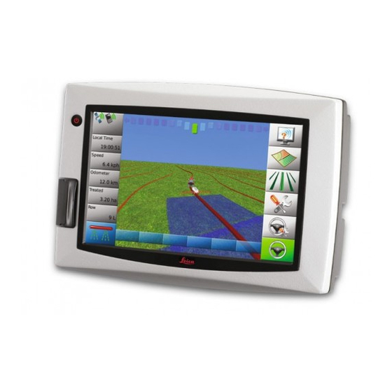
Components of the mojo3D System mojo3D compo- nents a) RAM mount - ball b) RAM mount - arm c) mojo3D display d) Glass-mount cell modem antenna e) Magnetic-mount GPS antenna Standard power cable g) Product documentation mojo3D_001 Leica mojo3D, System Overview... - Page 14 Leica mojo3D, System Overview mojo3D accessory • Port expansion cable options • Multi-Section control kit • Electric auto-steer kit • mojoRTK console • mojoRTK external control cable • mojoXact • GeoPRO antenna Refer to "Appendix A mojo3D Enhancements" for more information about the acces-...
-
Page 15: Features And Specifications
Simple installation, with RAM mount and colour-coded quick-install antennas • Integrated L1 GPS receiver • Integrated cell modem, CDMA or HSDPA depending on region ordered • 12 volt operation • Internal storage for waylines, worked areas, and settings Leica mojo3D, System Overview... - Page 16 Leica mojo3D, System Overview Caution Operation by touch screen: The mojo3D is designed to be used by a finger tapping the display screen. It may affect warranty if operated with a hard object i.e. stylus or pen.
-
Page 17: Mojo3D Software
Optional Radar-out signal for auxiliary devices that require a radar speed signal. • Leica Twist compatible for terrain compensated electric auto steer. • Leica mojoRTK Console or mojoXact compatible for base station RTK, Network RTK, and Dual Frequency GL1DE™. Leica mojo3D, System Overview... -
Page 18: Mojo3D Guidance
• On-screen lightbar with heading assist operation. • Electric auto-steer capable, with Electric Steer Kit. • Hydraulic auto-steer capable, with Leica mojoRTK Console or Leica mojoXact. 1.3.5 mojo3D Section Control and Mapping mojo3D section • Single-section control using port expansion cable control and •... - Page 19 Leica mojo3D, System Overview...
-
Page 20: System Installation
The installer must be able to use the system in accordance with the user manual. Leica Geosystems recommends that installation of the mojo3D equipment be performed by a qualified technician, because instal- lation requires making electrical connections. - Page 21 • The average installation time will vary, but it should be approximately two to four hours per vehicle. The time of installation may be more or less, based on vehicle type and options purchased. Leica mojo3D, System Installation...
-
Page 22: Mojo3D Installation
Leica mojo3D, System Installation mojo3D Installation RAM mount and Select an appropriate place to mount the mojo3D display. mojo3D display The display needs to be within easy reach of the operator when seated in installation the normal operating position, and ideally it will be easily visible in the forward field of vision of the operator. - Page 23 2. Route and secure all cables and wiring to ensure that there is no chafing or rubbing, which can cause premature failure. 3. Connect the power cable to the power connector on the rear of the mojo3D display. mojo3D_007 Leica mojo3D, System Installation...
- Page 24 Leica mojo3D, System Installation The mojo3D is a 12-volt DC (negative-to-earth) system only. Master input The optional master input on the mojo3D power cable may be connected to an external switch for remote operation of the Master Record Status button which starts and stops coverage recording on screen.
-
Page 25: Antenna Installation
2. Make sure that the installa- tion area is clean and dry. 3. Mount the GPS antenna on the roof of the vehicle. Use the adhesive tape provided. mojo3D_004 Leica mojo3D, System Installation... - Page 26 The antenna must be mounted horizontally and not on an angle to ensure best GPS reception possible. • If the mojo3D is to be connected to a Leica mojoRTK, the mojo3D GPS antenna is not required, however the cell modem antenna is still required.
- Page 27 5 cm (2") from the surrounding metal frame. • no closer than 20 cm (8") to the oper- ator's normal driving position. • Check that placement of antenna does not interfere with users field of vision. mojo3D_005 Leica mojo3D, System Installation...
- Page 28 Leica mojo3D, System Installation Connect the purple cell modem antenna cable to the purple connector on the rear of the mojo3D display. The antenna connectors and sockets on the Leica mojo3D are colour coded to ensure correct connection. mojo3D_009 ...
-
Page 29: Sim Card Installation
SIM card is securely seated in the holder. 6. Insert the SIM card holder back into the SIM card slot. 7. Replace the cover, and replace screws to secure. mojo3D_003 Leica mojo3D, System Installation... - Page 30 Leica mojo3D, System Installation When the mojo3D is turned on the cell phone icon should appear with signal strength. Caution The mojo3D must remain face down on a workbench when inserting a SIM card to remove the possibility of the SIM card being dropped inside the mojo3D.
- Page 31 Leica mojo3D, System Installation...
-
Page 32: Running The Mojo3D For The First Time
Leica mojo3D, Running the mojo3D for the First Time Running the mojo3D for the First Time Starting Up power button Starting up, 1. To start the mojo3D, press and hold the for two seconds. step-by-step 2. The splash screen appears on the mojo3D display, and is replaced by the warning signs screen, shown below. - Page 33 3. Once system initialisation is complete, the screen calibration icon appears in the top left-hand corner of the screen. This icon is used to set the screen cali- bration. Refer to "3.2 Setting the Screen Calibration" for more information. Leica mojo3D, Running the mojo3D for the First Time...
-
Page 34: Setting The Screen Calibration
Leica mojo3D, Running the mojo3D for the First Time Setting the Screen Calibration General informa- Differences may exist between different devices, and so the screen calibration must tion be set before operation. Setting the screen 1. Tap - with your finger, not an object - the middle of the screen calibration size, step-by-step icon, which is in the top left-hand corner of the screen. -
Page 35: Initial Setup Wizard
• If another option was selected, then the configuration setup for the selected device is displayed. Refer to "Appendix A mojo3D Enhancements" for more information on the setup of the other devices. Leica mojo3D, Running the mojo3D for the First Time... - Page 36 Leica mojo3D, Running the mojo3D for the First Time Brightness adjust- 1. Adjust the slider to vary the brightness of the screen, by tapping ment, step-by-step 2. Tap to continue. Country selection, 1. On the country selection screen, tap the button labelled with the flag of your step-by-step country.
- Page 37 2. After making your selections, tap to continue. Lightbar mode The default lightbar mode is the Leica Geosystems Smart lightbar which uses both setup, cross track error and heading error to guide you to the line. The other choice offered step-by-step is the traditional Crosstrack only lightbar.
- Page 38 Leica mojo3D, Running the mojo3D for the First Time 3. If you selected Crosstrack, more configuration options are now available on the Lightbar Mode screen. • Chase: when Chase mode is on (green), the lightbar represents where the line is relative to where the vehicle is, and to steer to the line, you steer towards the light - that is, you chase the light.
- Page 39 3. Tap on the on-screen keyboard. • Username Field 1. Tap the Username field. The on-screen keyboard appears. 2. Tap the keys on the on-screen keyboard to enter the user name. Leica mojo3D, Running the mojo3D for the First Time...
- Page 40 1. Check the box for the appropriate cell network mode. 2. Tap to continue. Virtual Vista setup, To connect the mojo3D to Virtual Vista you must have a Virtual Vista account. The step-by step process of registering for an account is explained in the Leica Virtual Vista User...
- Page 41 • Repeat for the other measurements required. 3. After you have entered all required vehicle measurements, add any required implements on the same screen. If no implements are required, tap continue. Leica mojo3D, Running the mojo3D for the First Time...
- Page 42 Leica mojo3D, Running the mojo3D for the First Time Implement setup, To add an implement carry out the following steps: step-by-step 1. On the vehicle setup screen, tap An implement button appears in the bar at the top of the screen and the list of implement types are shown.
- Page 43 • Single Section: a maximum of one section can be setup for the vehicle. This section is automatically controlled with physical output on the port expansion cable. • Leica AS400: multiple sections are automatically controlled via the Leica AS400 section controller hardware, supplied with the multi-section control kit. ...
- Page 44 Master wire on the mojo3D power cable. • Leica AS400 / Single: the on screen coverage mapping is activated by sensing a voltage connected to the Master wire on the Leica AS400 controller port.
- Page 45 • On latency: the number of seconds it takes from the section being turned on until the actual application starts. Refer to "7 Automatic Section Control" for more detail on the individual settings. 5. When you have entered all required data tap to continue. Leica mojo3D, Running the mojo3D for the First Time...
- Page 46 Leica mojo3D, Running the mojo3D for the First Time Correction source 1. On the Correction Source screen, select the correction source to use for your configuration, system. step-by step 2. Tap to continue. • If Network DGPS is selected, further configuration is required and this is described in "10.1 Network DGPS".
- Page 47 Primarily status information is The buttons down the right hand side of displayed on the left hand side. the display are the main buttons used to navigate through the system. Leica mojo3D, Running the mojo3D for the First Time...
- Page 48 Leica mojo3D, Running the mojo3D for the First Time If the menu buttons on the left or the right side of the main navigation screen have not been touched for 20 seconds, they fade away to provide a larger view of the field, as shown below.
-
Page 49: Menu Buttons At Right Of Screen
Guidance page 50. Settings Auto-steer If the mojo3D is being used without Settings additional auto-steer options, then the Auto-steer Settings button and the Auto-steer button will be disa- Auto-steer bled. Leica mojo3D, Running the mojo3D for the First Time... - Page 50 Leica mojo3D, Running the mojo3D for the First Time Flyout Menu Example...
-
Page 51: Menu Buttons At Left Of Screen
• Base station (if used) • Satellites visible • Cell modem signal strength Five buttons with • Virtual Wrench™ (if connected) user-selected data. Refer to see "3.9 Error Notifications" for more information. Master record status Leica mojo3D, Running the mojo3D for the First Time... -
Page 52: Specifying Data For Display
Leica mojo3D, Running the mojo3D for the First Time Specifying Data for Display Specifying data for The items displayed at the left of the main navigation screen may be selected by the display, user. To specify the items for display, carry out the following steps: step-by-step 1. - Page 53 3. To set the odometer display to zero, tap the reset odometer button at the right of the screen. 4. Tap to return to the main navigation screen. Leica mojo3D, Running the mojo3D for the First Time...
-
Page 54: Zoom Buttons
Leica mojo3D, Running the mojo3D for the First Time Zoom Buttons Using zoom To use the zoom buttons, carry out the following steps: buttons, step-by- • To display the zoom buttons, touch the middle of the screen, the zoom buttons step will appear on the main navigation screen. -
Page 55: View Modes
1. Touch the middle of the screen, to display the zoom buttons. 2. Tap either repeatedly, until the view mode changes. To change between Top Down North Up and Top Down Heads Up refer to "3.11 Changing System Settings". Leica mojo3D, Running the mojo3D for the First Time... -
Page 56: Error Notifications
Leica mojo3D, Running the mojo3D for the First Time Error Notifications When any error occurs, the background of the status button goes red. General informa- To view information about the error tap the button. tion At any time the complete list of recent errors can be viewed. - Page 57 Over- view button. 3. For a list of local errors, tap the local errors button. 4. Tap on an error in the list to display more information. Leica mojo3D, Running the mojo3D for the First Time...
- Page 58 Leica mojo3D, Running the mojo3D for the First Time 5. If an external device that supports error reporting is attached tap the remote errors button for a list of remote errors. 6. Tap to return to the main navigation screen.
- Page 59 3. To return to the main navigation screen, tap the button. Leica mojo3D, Running the mojo3D for the First Time...
-
Page 60: Running The Setup Wizard At Any Time
Leica mojo3D, Running the mojo3D for the First Time 3.10 Running the Setup Wizard at any Time General informa- The initial setup wizard can be run again at any time after the initial setup. tion The wizard guides you through the whole system setup: System Setup, Vehicle Setup, Attached Device Selection, NMEA Configuration. -
Page 61: Changing System Settings
Make any changes that are required. For specific information on the different settings refer to "3.3 Initial Setup Wizard". All changes are automatically saved as they are made. Leica mojo3D, Running the mojo3D for the First Time... -
Page 62: Vehicle Setup
Leica mojo3D, Running the mojo3D for the First Time 3.12 Vehicle Setup General informa- Vehicle setup includes: tion • Vehicle & Implement setup • Section controller and Implement mode selection • Master Input & Input Mode selection • Swath and Section control setup... -
Page 63: Attached Device Selection
2. On the flyout menu, tap the Attached device selection button. 3. On the attached device selection screen, tap the button that describes your setup, for example the Leica mojoXact Plus. Leica mojo3D, Running the mojo3D for the First Time... - Page 64 Leica mojo3D, Running the mojo3D for the First Time 4. Tap to continue through the attached device wizard. Make any changes that are required. Refer to "Appendix A mojo3D Enhancements" for more information on these setups. All changes are automatically saved when proceeding to the next screen.
-
Page 65: Nmea Configuration
NMEA wizard. Make any changes that are required. For specific information on the different settings refer to "11 NMEA Output". All changes are automatically saved as they are made. Leica mojo3D, Running the mojo3D for the First Time... -
Page 66: Feature Unlock
Leica mojo3D, Running the mojo3D for the First Time 3.15 Feature Unlock Feature unlock, For some configurations the feature unlock button may not be available. In cases step-by-step where some features are locked, new authorisation codes can be entered using the feature unlock. - Page 67 Leica mojo3D, Running the mojo3D for the First Time...
-
Page 68: Setting Guidance Types
Leica mojo3D, Setting Guidance Types Setting Guidance Types Waypoints Waypoints are used to define a line in the field to which all working lines will be parallel. Waypoints must be set before auto-steer can be used. AB Parallel Guidance In AB Parallel guidance, working lines are parallel,... - Page 69 5. On the dialog box that appears: • tap to save the wayline to memory. An on-screen keyboard appears. Enter a name for the wayline, and tap • tap to use the wayline without first saving it to memory. Leica mojo3D, Setting Guidance Types...
-
Page 70: A+ Heading Guidance
Leica mojo3D, Setting Guidance Types A+ Heading Guidance In A+ heading guidance, working lines are parallel, General informa- and are set by defining an initial waypoint and a tion compass bearing. Before you can set waypoints, the system must have a good position fix. - Page 71 5. On the dialog box that appears: • tap to save the wayline to memory. An on-screen keyboard appears. Enter a name for the wayline, and tap • tap to use the wayline without first saving it to memory. Leica mojo3D, Setting Guidance Types...
-
Page 72: Fixed Contour Guidance
Leica mojo3D, Setting Guidance Types Fixed Contour Guidance In fixed contour guidance, working lines are parallel General informa- curves, and are set by defining an initial contour tion with a beginning and an ending waypoint. Before you can set waypoints, the system must have a good position fix. - Page 73 6. On the dialog box that appears: • tap to save the wayline to memory. An on-screen keyboard appears. Enter a name for the wayline, and tap • tap to use the wayline without first saving it to memory. Leica mojo3D, Setting Guidance Types...
-
Page 74: Pivot Guidance
Leica mojo3D, Setting Guidance Types Pivot Guidance In pivot guidance, working lines are concentric General informa- circles and are defined by setting three waypoints. tion Before you can set waypoints, the system must have a good position fix. Setting pivot guid-... - Page 75 6. On the dialog box that appears: • tap to save the wayline. An on-screen keyboard appears. Enter a name for the wayline, and tap • tap to use the wayline without first saving it to memory. Leica mojo3D, Setting Guidance Types...
-
Page 76: Ultimate Curve Guidance
Leica mojo3D, Setting Guidance Types Ultimate Curve Guidance Benefits Ultimate Curve guidance provides guidance alongside any previously recorded coverage. This means guidance can be provided around practically any irregular shaped field or back and forth along a complex contour line. As there is no need to pre-define a shape, Ultimate Curve guidance can be activated at anytime and guid- ance alongside any previous coverage will be provided. - Page 77 5. Use the on–screen number pad to enter a value for the minimum turn radius. 6. Tap on the number pad to complete the value entry. 7. Tap to continue through the vehicle setup and return to the main navigation screen. Leica mojo3D, Setting Guidance Types...
- Page 78 Leica mojo3D, Setting Guidance Types Setting Ultimate To use Ultimate Curve guidance, carry out the following steps: Curve guidance, 1. On the main navigation screen, tap the master record button. step-by-step 2. Drive the first pass or lap in the field and position the vehicle for the next pass.
-
Page 79: Stop Guidance
1. On the main navigation screen, tap the guidance button. 2. On the flyout menu, tap the stop guidance button. You are returned to the main navigation screen which is now clear of guidance information. Leica mojo3D, Setting Guidance Types... -
Page 80: Guidance Management
Leica mojo3D, Setting Guidance Types Guidance Management 4.7.1 Saving a Wayline Automatic saving Every time a wayline is set a dialog box is displayed which allows the line to be imme- diately saved by tapping . The line can be used without first saving by tapping... -
Page 81: Changing The Name Of A Wayline
2. On the flyout menu, tap the wayline management button. 3. Tap the name of the wayline that you wish to change, and then tap the edit button. 4. Use the on-screen keyboard to enter the new name for the wayline, and tap Leica mojo3D, Setting Guidance Types... -
Page 82: Deleting An Individual Wayline
Leica mojo3D, Setting Guidance Types 4.7.3 Deleting an Individual Wayline General informa- A wayline stored on the mojo3D can be deleted. Once a wayline has been deleted, it tion cannot be recovered, unless it has been backed up to a USB Flash Drive before. -
Page 83: Deleting All Waylines
3. On the screen that lists the names of the waylines, tap the delete all waylines button. 4. On the dialog box that appears: • tap to confirm deletion. • tap to cancel the operation. Leica mojo3D, Setting Guidance Types... - Page 84 Leica mojo3D, Setting Guidance Types 5. Tap to return to the main navigation screen.
-
Page 85: Exporting Waylines
USB drives with the mojo3D products. Do not turn off the mojo3D, or remove the USB Flash Drive, while the wayline export is under way. You can export mojo3D files or Google Earth files or Shapefile files. Leica mojo3D, Setting Guidance Types... - Page 86 Leica mojo3D, Setting Guidance Types Exporting waylines, To export all waylines stored in the mojo3D in a mojo3D file format, carry out the step-by-step following steps: 1. The USB interface is on the lower left front of the mojo3D display. Lift the rubber cover and insert a compatible USB Flash Drive into the USB slot.
- Page 87 Flash Drive there will be a message to confirm overwriting the waylines. 6. On the dialog box that appears: • tap to overwrite the waylines on the USB Flash Drive. • tap to cancel the operation. 7. Tap to return to the main navigation screen. Leica mojo3D, Setting Guidance Types...
- Page 88 Leica mojo3D, Setting Guidance Types Exporting Google To export Google Earth and Shapefile data for a selected wayline, carry out the Earth and Shapefile following steps: data for a selected 1. The USB interface is on the lower left front of the wayline, step-by- mojo3D display.
- Page 89 7. To close the message box and return to the wayline management screen, tap the button. 8. To return to the main navigation screen, tap the button. Leica mojo3D, Setting Guidance Types...
-
Page 90: Importing Waylines
Leica mojo3D, Setting Guidance Types 4.7.6 Importing Waylines General informa- Waylines in the following formats can be imported into a mojo3D: tion • mojo3D files. • Google Earth kml files. • Shapefile shp, dbf, prj and shx files. Refer to "Appendix B Formatting USB Flash Drives" for important informa- tion about using USB drives with the mojo3D products. - Page 91 USB slot. mojo3D_010 2. On the main navigation screen, tap the settings button. 3. On the flyout menu, tap the transfer data button. 4. Tap the import from USB button and tap to continue. Leica mojo3D, Setting Guidance Types...
- Page 92 Leica mojo3D, Setting Guidance Types If a mojoRTK is attached, waylines can be transferred from the mojoRTK to the mojo3D by tapping the button shown. 5. Tap the Guidance button and tap to continue. If there is no wayline data on the USB Flash Drive the guid- ance button will not be displayed.
- Page 93 1. The USB interface is on the lower left front of the mojo3D display. Lift the rubber cover and insert a compatible USB Flash Drive that contains the wayline data into the USB slot. mojo3D_010 Leica mojo3D, Setting Guidance Types...
- Page 94 Leica mojo3D, Setting Guidance Types 2. On the main navigation screen, tap the guidance button. 3. On the flyout menu, tap the wayline management button. The Wayline Management screen appears. 4. Tap the import from USB button. (Note that the arrow goes from the USB memory key to the Google Earth icon - not the other way round.)
- Page 95 USB memory key, the SHP button is disabled. The Select the items to import screen appears. 6. Select the waylines to import by tapping their names. You can select one wayline, many waylines, or all waylines by tapping the Select all button. Leica mojo3D, Setting Guidance Types...
- Page 96 Leica mojo3D, Setting Guidance Types 7. Tap the button. If there are waylines with the same name already on the mojo3D, the Renaming required screen appears to allow the conflicting waylines to be renamed. • To have the mojo3D automatically create new names, select Automatic.
-
Page 97: Replay Guidance
2. On the flyout menu, tap the wayline management button. The Wayline Management screen appears, with all of the saved waylines and saved treatments listed. 3. Select the treatment to load as a guidance pattern from the list by tapping its name. Leica mojo3D, Setting Guidance Types... - Page 98 Leica mojo3D, Setting Guidance Types 4. To proceed with loading the treatment, tap the button. You are returned to the main navigation screen and the path of the selected treatment displays on the screen. To abandon loading the treatment, tap the button.
-
Page 99: Field Offset
1. On the main navigation screen, tap the guidance button. step 2. On the flyout menu, tap the field offset button. 3. Tap the field offset value box. The on–screen number pad appears. Leica mojo3D, Setting Guidance Types... - Page 100 Leica mojo3D, Setting Guidance Types 4. Use the on–screen number pad to enter a value for the field offset. Tap the number pad when finished. 5. Tap to return to the main navigation screen.
-
Page 101: Nudge
• Automatically adjust to the GPS positions to the vehicle by tapping the message in the centre of the screen. • Tap to move the GPS position by a small step. 4. Tap or simply wait for the menu to disappear. Leica mojo3D, Setting Guidance Types... -
Page 102: Auto-Steer
Leica mojo3D, Auto-Steer Auto-Steer Engage Auto-Steer Auto-steer status The auto-steer button on the main navigation screen is used to engage and disen- gage auto-steer. The colour of this button also indicates the current status of the auto-steer. • Red: Roading is active and auto-steer can not be engaged until roading is turned off. - Page 103 To enable roading, carry out the following steps: 1. On the main navigation screen, tap the steering settings button. 2. On the flyout menu, tap the roading button. 3. Roading will be enabled and the auto-steer button will turn red. Leica mojo3D, Auto-Steer...
- Page 104 Leica mojo3D, Auto-Steer Preconditions to The conditions required for auto-steer to engage will depend on the steer kit being engage auto-steer used. The following is a typical example of the conditions required to be met before automatic steering can occur: •...
- Page 105 2. The auto-steer button will turn red to indicate auto-steer is disengaged and the vehicle is no longer being automatically steered. Other methods to disengage the steering will be available and this method will depend on the steer kit used. Leica mojo3D, Auto-Steer...
-
Page 106: Tuning Auto-Steer Performance
Leica mojo3D, Auto-Steer Tuning Auto-Steer Performance General informa- The tuning of the mojo3D is pre-loaded based on your selected vehicle/steering kit tion type and should be a reasonable starting point for tuning refinement. To refine the tuning of the system, there are four parameters: •... - Page 107 • Each setting is specified by a nominal scale from 50 to 150. • The value of the setting is adjusted by moving an on-screen slider. • The auto-steer performance is shown in the panel on the right hand side of the screen. Leica mojo3D, Auto-Steer...
- Page 108 Leica mojo3D, Auto-Steer Saving tuning data • to save all changes made to the settings, and return to the main naviga- tion screen. • to return to the main navigation screen without saving any changes made to any of the tuning parameters.
-
Page 109: Sensitivity
The sensitivity can be set between 50% and 150%. The standard setting is 100%. • In general, higher sensitivity is for slower travelling speed, lower sensitivity for faster speed. • Different sensitivity settings and their approach to the working line: 150% 100% mojoRTK_011 Leica mojo3D, Auto-Steer... -
Page 110: Aggressiveness
Leica mojo3D, Auto-Steer 5.2.3 Aggressiveness Setting the aggres- The aggressiveness will control the rate that the vehicle attacks the line and how well siveness it holds the line. 1. On the tuning screen, tap the aggressiveness button. 2. Adjust the slider to vary the aggressiveness, by using the Explanation •... -
Page 111: Overshoot
2. Adjust the slider to vary the overshoot, by using the Explanation • The overshoot can be set between 50% and 150%. The standard setting is 100%. • Different overshoot settings and their approach to the working line: 150% 100% mojoRTK_013 Leica mojo3D, Auto-Steer... -
Page 112: Speed Adjust
Leica mojo3D, Auto-Steer 5.2.5 Speed Adjust Setting the speed The speed adjust should be used to fine tune the performance of the control system adjust for higher speeds than the tuning speed of 5 km/h (3 mph). Typically, the vehicle can steer side to side at higher speeds, and this can be resolved by reducing the speed adjust. -
Page 113: Tuning Tips
Vehicle is too fast to approach the line or the Decrease the Aggressiveness. vehicle oscillates. Vehicle straightens up before it gets to the line. Increase the Overshoot. Vehicle drives past the line then comes back Decrease the Overshoot. onto to the line. Leica mojo3D, Auto-Steer... - Page 114 Leica mojo3D, Auto-Steer Symptom Resolution Vehicle turns very slowly to drive toward the Increase the Sensitivity. line. Vehicle turns very aggressively to drive toward Reduce the Sensitivity. the line and twitches when on the line. Vehicle oscillates only at higher speeds.
-
Page 115: Swap Left And Right Steering Control
To swap left and right steering control, carry out the following steps: right steering 1. On the main navigation screen, tap the auto-steer settings control, step-by- button. step 2. On the flyout menu, tap the steer settings button. The Valves Reversed screen appears. Leica mojo3D, Auto-Steer... - Page 116 Leica mojo3D, Auto-Steer 3. Select the option required, either Normal or Reversed, by tapping the appropriate button. 4. To save the selection, tap the button. The saving screen appears showing the progress of the operation. 5. To return to the main navigation screen, tap the...
-
Page 117: Stationary Engage And Reverse Steering
The operator can then stop, go forward again and the auto-steer is still engaged. This can be Leica mojo3D, Auto-Steer... - Page 118 Leica mojo3D, Auto-Steer repeated a number of times without the operator needing to re-engage the auto-steer. Enabling To enable stationary engage and reverse steering, carry out the following steps: Stationary Engage 1. On the main navigation screen, tap the settings button.
- Page 119 To disable a feature tap its green box, and it becomes grey indicating that the feature is now disabled. If Reverse Steering is enabled, then Stationary Engage is automatically enabled as Reverse Steering requires Stationary Engage to be enabled. Conversely, if Stationary Engage is disabled then Reverse Steering is automatically disabled. Leica mojo3D, Auto-Steer...
- Page 120 Leica mojo3D, Auto-Steer Setting the At the Stationary Engage and Reverse Steering screen, you can set the Stationary stationary engage Engage Time Limit to change how long the stationary engage system will stay time limit, step-by- engaged when the vehicle is not moving. The default time limit is 15 seconds but it step can be set anywhere from 1 to 30 seconds.
- Page 121 • the vehicle must have an attack angle with the line of less than 20 degrees. • the vehicle must be travelling at less than 6mph (10kph). • stationary engage must be enabled. • reverse steering must be enabled. 2. Engage auto-steer while driving in reverse. Leica mojo3D, Auto-Steer...
- Page 122 Leica mojo3D, Auto-Steer If auto-steer is engaged with the vehicle driving forwards, and the vehicle is on an AB or A+ heading wayline, and stationary engage is enabled, then reverse engage can be used by driving in reverse, providing the time between the forwards and reverse motion is shorter than the stationary engage time limit.
-
Page 123: Testing Auto-Steer
To perform a test on the auto-steer function, carry out the following steps: steer function, 1. On the main navigation screen, tap the auto-steer settings step-by-step button. 2. On the flyout menu, tap the auto-steer test button. The Configure Steering Kit screen, shown below, appears. Leica mojo3D, Auto-Steer... - Page 124 Leica mojo3D, Auto-Steer If the mojo3D system thinks that the steering controller is not configured, the Configure Steering Kit screen appears with only the Start button visible, giving the operator the only option to write the configuration to the steering controller.
- Page 125 10. Tap the centre button, and check that the steering wheel turns to the centred position. Note that not all steer kits offer this function- ality. 11. Tap the turn right button, and check that the steering wheel turns to the right. Leica mojo3D, Auto-Steer...
- Page 126 Leica mojo3D, Auto-Steer 12. After completing the steering test, disengage the auto-steer by tapping the auto-steer is engaged button. 13. Tap to return to the main navigation screen.
- Page 127 Leica mojo3D, Auto-Steer...
-
Page 128: Treatments
Leica mojo3D, Treatments Treatments General informa- • Field treatments record the coverage activity that the user initiates by tapping tion on the master record status button. • Coverage data is added in real time to the current field treatments record. -
Page 129: Starting A New Treatment
A previously saved wayline or guidance pattern can be loaded without turning the treatment off. This allows a wayline to be used for the treatment application. Leica mojo3D, Treatments... -
Page 130: Load A Stored Treatment
Leica mojo3D, Treatments Load a Stored Treatment Load a stored To load a stored treatment, carry out the following steps: treatment, 1. On the main navigation screen, tap the mapping button. step-by-step 2. On the flyout menu, tap the management button. -
Page 131: Changing A Treatment Name
Tap the treatment name to select it. 4. Tap the edit button. 5. Use the on-screen keyboard to change the name of the treatment, and then 6. Tap to return to the main navigation screen. Leica mojo3D, Treatments... -
Page 132: Creating A Pdf Report Of A Treatment
Leica mojo3D, Treatments Creating a PDF Report of a Treatment General informa- A PDF report of a treatment can be created directly on the mojo3D and exported to tion a USB Flash Drive. The report contains an image of the coverage map, the treatment’s name, area covered, start date and time, and end date and time. - Page 133 6. To load the selected treatment, tap the button. You are returned to the main navigation screen. To leave the current treatment loaded, tap the button. You are returned to the main navigation screen. Leica mojo3D, Treatments...
-
Page 134: Deleting A Treatment
Leica mojo3D, Treatments Deleting a Treatment Deleting a treat- A treatment may be deleted however care must be taken as if the treatment is used ment, step-by-step as a guidance pattern for replay guidance (see "4.7.7 Replay Guidance") and the treatment is deleted, the replay wayline file will also be deleted. - Page 135 6. To load the selected treatment, tap the button. You are returned to the main navigation screen. To leave the current treatment loaded, tap the button. You are returned to the main navigation screen. Leica mojo3D, Treatments...
-
Page 136: Exporting Treatment Data
Leica mojo3D, Treatments Exporting Treatment Data General informa- Treatment data is exported in the following formats: tion • mojo3D files. • Google Earth kmz and kml files - contain the treatment map/coverage, any boundary that may be associated with the treatment and a Replay Wayline which is the path used to create the treatment. - Page 137 USB Flash Drive into the USB slot. mojo3D_010 2. On the main navigation screen, tap the settings button. 3. On the flyout menu, tap the transfer data button. 4. Tap the export to USB button and tap to continue. Leica mojo3D, Treatments...
- Page 138 Leica mojo3D, Treatments 5. Tap the Field button and tap to continue. If there is already data on the USB Flash Drive there will be a message to confirm overwriting the data. 6. On the dialog box that appears: •...
- Page 139 2. On the main navigation screen, tap the mapping button. 3. On the flyout menu, tap the management button. The Field Management screen appears. 4. Tap to scroll though the list of treatments. To select the treatment to export, tap the treatment name. Leica mojo3D, Treatments...
- Page 140 Leica mojo3D, Treatments 5. To export the selected treatment’s data, tap the export to USB button. (Note that the export button has the arrow pointing to the USB memory key.) Depending on the size of the treatment map, the export operation may take a minute or more.
- Page 141 7. To close the message box and return to the field management screen, tap the button. 8. To load the selected treatment, tap the button. You are returned to the main navigation screen. To leave the current treatment loaded, tap the button. You are returned to the main navigation screen. Leica mojo3D, Treatments...
-
Page 142: Importing Treatment Data
Leica mojo3D, Treatments Importing Treatment Data Importing treat- Refer to "Appendix B Formatting USB Flash Drives" for important informa- ment data, step- tion about using USB drives with the mojo3D products. by-step Do not turn off the mojo3D, or remove the USB Flash Drive, while the treat- ment data import is under way. - Page 143 If there is no field data on the USB Flash Drive the button will not be displayed. The Select the items to import screen appears. Select the treatments by tapping their buttons. You can select one treatment, many treatments or all treatments by tapping the Select All button. Leica mojo3D, Treatments...
- Page 144 Leica mojo3D, Treatments 6. Tap the button. If there are treatments with the same name already on the mojo3D, the Renaming required screen displays to allow the conflicting treatments to be renamed. • To have the mojo3D automatically create new names, select Automatic. The mojo3D adds a number to the imported treatments’...
- Page 145 8. To return to the main navigation screen tap the button. Leica mojo3D, Treatments...
-
Page 146: Automatic Section Control
Leica mojo3D, Automatic Section Control Automatic Section Control General informa- The master record status button in the bottom left corner of the screen may be tion red, yellow, or blue. • Master on, coverage recording. • Master on, but paused because of low or high speed. -
Page 147: Section Control Latency
ON and the application physically starting. This may be a very small value - a few tenths of a second - and hard to measure accurately. Latency can be measured more accurately by measuring the distance travelled at a given speed. Leica mojo3D, Automatic Section Control... -
Page 148: Calibrating The Section Control Latency Value
Leica mojo3D, Automatic Section Control 7.1.1 Calibrating the Section Control Latency Value For the purpose of this calibration exercise, if using a boom spray, the tank should contain only water. Calibrating latency, To calibrate the section control latency value, carry out the following steps: step-by-step 1. - Page 149 Example Assuming that the operator was travelling at 20 km/h and the distance from the rope to where the application reacted is 5 m: 5 m ÷ 20 km/h x 3.6 = 0.9 seconds Latency Leica mojo3D, Automatic Section Control...
-
Page 150: Troubleshooting Latency Problems
Leica mojo3D, Automatic Section Control Imperial/US calcu- Latency [s] = Distance travelled [ft] ÷ Speed [mph] x 0.68 lation Example Assuming that the operator was travelling at 12 mph and the distance from the rope to where the application reacted is 16 ft: 16 ft ÷... - Page 151 The section is turned OFF too Decrease the OFF latency early, and a missed area results. value. The section takes too long to Increase the ON latency turn ON, and a missed area value. results. Leica mojo3D, Automatic Section Control...
- Page 152 Leica mojo3D, Automatic Section Control Problem Solution The section turns ON too early, Decrease the ON latency and an overlap results. value.
-
Page 153: Setting The Overlap Limit
If the overlap limit is decreased, the system will not turn on the application when traversing a small missed area, such as a strip between two spray swaths. 100% Leica mojo3D, Automatic Section Control... - Page 154 Leica mojo3D, Automatic Section Control Setting the overlap To set the overlap limit, carry out the following steps: limit, step-by-step 1. On the main navigation screen, tap the settings button. 2. On the flyout menu, tap the Vehicle setup button.
-
Page 155: Setting The Low-Speed Shutoff
Setting low-speed To set the low-speed shutoff, carry out the following steps: shutoff, step-by- 1. On the main navigation screen, tap the settings button. step 2. On the flyout menu, tap the Vehicle setup button. Leica mojo3D, Automatic Section Control... - Page 156 Leica mojo3D, Automatic Section Control 3. Tap several times until the Section Control Setup screen is shown. 4. Tap the Low Speed Shutoff value box. 5. Use the on–screen number pad to enter a value for the minimum speed. Tap on the number pad when finished.
-
Page 157: Section Override Control
• Off: The section is turned off, and will not apply coverage. • Auto: Auto section control will operate as normal. 4. Or, change all the settings at once by tapping All Auto, All On, or All Off. 5. Tap to close the section override control. Leica mojo3D, Automatic Section Control... -
Page 158: Field Boundary
Leica mojo3D, Field Boundary Field Boundary Create a New Field Boundary Benefits Field boundaries can be recorded and saved in the mojo3D. This means more precise application can be performed with less wastage as the total field area is known along with the area remaining to be covered. - Page 159 • Drive over the start point and the boundary will automatically close. The field boundary is automatically saved with the same name as the current treatment when it is closed. Leica mojo3D, Field Boundary...
-
Page 160: Load A Stored Field Boundary
Leica mojo3D, Field Boundary Load a Stored Field Boundary Load a stored field To load a stored field boundary, carry out the following steps: boundary, step-by- 1. On the main navigation screen, tap the mapping button. step 2. On the flyout menu, tap the boundary management button. -
Page 161: Changing A Field Boundary Name
2. On the flyout menu, tap the boundary management button. 3. Tap to scroll through the list of boundaries. Tap the boundary name to select it. 4. Tap the edit button. 5. Use the on-screen keyboard to change the name of the boundary, and tap Leica mojo3D, Field Boundary... -
Page 162: Deleting A Field Boundary
Leica mojo3D, Field Boundary Deleting a Field Boundary Deleting a field To delete a stored field boundary, carry out the following steps: boundary, step-by- 1. On the main navigation screen, tap the mapping button. step 2. On the flyout menu, tap the boundary management button. -
Page 163: Exporting Field Boundary Data
USB drives with the mojo3D products. Do not turn off the mojo3D, or remove the USB Flash Drive, while the data export is under way. You can export the mojo3D files or the Google Earth and Shapefile files. Leica mojo3D, Field Boundary... - Page 164 Leica mojo3D, Field Boundary Exporting field To export all field boundary data stored in the mojo3D in a mojo3D file format, carry boundary data, out the following steps: step-by-step 1. The USB interface is on the lower left front of the mojo3D display.
- Page 165 USB Flash Drive. The Export Summary screen displays, showing the progress and success of the export process. • tap to cancel the copy operation. 7. Tap to return to the main navigation screen. Leica mojo3D, Field Boundary...
- Page 166 Leica mojo3D, Field Boundary Exporting Google To export Google Earth and Shapefile data for a selected field boundary, carry out Earth and Shapefile the following steps: data for a selected 1. The USB interface is on the lower left front of the boundary, step-by- mojo3D display.
- Page 167 When the export of the field boundary data is complete, a message displays stating that the data has been saved. 7. To close the message box and return to the boundary management screen, tap button. Leica mojo3D, Field Boundary...
- Page 168 Leica mojo3D, Field Boundary 8. To load the selected field boundary, tap the button. You are returned to the main navigation screen. To leave the current boundary loaded, tap the button. You are returned to the main navigation screen.
-
Page 169: Importing Field Boundary Data
USB drives with the mojo3D products. Do not turn off the mojo3D, or remove the USB Flash Drive, while the data import is under way. You can import mojo3D files, Google Earth files or Shapefile files. Leica mojo3D, Field Boundary... - Page 170 Leica mojo3D, Field Boundary Importing field To import field boundary data from mojo3D files, carry out the following steps: boundary data 1. The USB interface is on the lower left front of the from mojo3D files, mojo3D display. Lift the rubber cover and insert a step-by-step compatible USB Flash Drive into the USB slot.
- Page 171 • Select manual to allow each field boundary to be manually renamed. 8. To proceed with the import, tap the button. The Import Summary screen displays showing the progress and success of the import. 9. Tap to return to the main navigation screen. Leica mojo3D, Field Boundary...
- Page 172 Leica mojo3D, Field Boundary Importing field Google Earth and Shapefile files for field boundaries that have been exported from a boundary data mojo3D can be imported by mojo3Ds. Some Shapefile files generated by third party from Google Earth applications can also be imported by mojo3Ds.
- Page 173 3. On the flyout menu, tap the boundary management button. The Boundary management screen displays. 4. Tap the import from USB button. (Note that the arrow goes from the USB memory key to the Google Earth icon - not the other way round.) Leica mojo3D, Field Boundary...
- Page 174 Leica mojo3D, Field Boundary If there are no Google Earth or Shapefile files on the USB memory key to import, the button is disabled. You may have the wrong file formats on the USB memory key or you may not have the files in the root folder of the USB memory key.
- Page 175 • To manually rename the imported boundaries, select Manual. 8. To proceed with the import, tap the button. The Import Summary screen displays indicating the progress and success of the import. Leica mojo3D, Field Boundary...
- Page 176 Leica mojo3D, Field Boundary 9. To return to the Boundary management screen, tap the button. The newly imported boundaries now appear in the Boundary management screen and are available for loading. 10. To return to the main navigation screen, tap the...
- Page 177 Leica mojo3D, Field Boundary...
-
Page 178: Vehicles And Implements
Leica mojo3D, Vehicles and Implements Vehicles and Implements Overview The mojo3D supports: • Saving vehicle and implement configurations • Loading previously saved vehicle and implement configurations • Renaming vehicle and implement configurations • Deleting vehicle and implement configurations • Exporting vehicle and implement configurations to a USB memory key •... -
Page 179: Saving A Vehicle Or Implement Configuration
2. On the flyout menu, tap the vehicle setup management button. The Vehicle Setup Management screen, shown below, displays. The Vehicle list (on the left) is empty if you have no previously saved configurations. Leica mojo3D, Vehicles and Implements... - Page 180 Leica mojo3D, Vehicles and Implements 3. To save the current vehicle configuration, tap the button. The saved configuration appears in the list on the left with a default name as shown below. The configuration can be renamed by following the steps in "9.3 Renaming a Vehicle or Implement Configuration".
-
Page 181: Load A Vehicle Or Implement Configuration
The system cannot detect if incorrect settings have been loaded. Loading a vehicle To load a vehicle or implement configuration, carry out the following steps: or implement configuration, 1. On the main navigation screen, tap the settings button. step-by-step Leica mojo3D, Vehicles and Implements... - Page 182 Leica mojo3D, Vehicles and Implements 2. On the flyout menu, tap the vehicle setup management button. The Vehicle Setup Management screen, shown below, displays with the currently saved configurations listed on the left. 3. Tap the configuration to be loaded to select it.
-
Page 183: Renaming A Vehicle Or Implement Configuration
Renaming a vehicle To rename a vehicle or implement configuration, carry out the following steps: or implement configuration, 1. On the main navigation screen, tap the settings button. step-by-step Leica mojo3D, Vehicles and Implements... - Page 184 Leica mojo3D, Vehicles and Implements 2. On the flyout menu, tap the vehicle setup management button. The Vehicle Setup Management screen, shown below, displays with the currently saved configurations listed on the left. 3. Select the configuration to be renamed by tapping it.
- Page 185 7. To return to the main navigation screen, tap the button. This leaves the currently loaded configuration unchanged. To load the configuration that is currently selected in the list, tap button. Leica mojo3D, Vehicles and Implements...
-
Page 186: Deleting Vehicle Or Implement Configurations
Leica mojo3D, Vehicles and Implements Deleting Vehicle or Implement Configurations General Informa- Vehicle configurations that are incorrect or no longer required, can be deleted. tion TAKE CARE...once a configuration is deleted it cannot be recovered or restored. If you accidentally delete a configuration you will need to manu- ally recreate it and save it again. - Page 187 4. Ensure that the currently selected configuration is the one that you want to delete. 5. To permanently delete the selected configuration, tap the delete button. A dialog box displays asking you to confirm that you want to proceed with the deletion. Leica mojo3D, Vehicles and Implements...
- Page 188 Leica mojo3D, Vehicles and Implements 6. To proceed with the deletion of the configuration, tap the button. The configuration is permanently deleted. To cancel the deletion and leave the configuration saved on the mojo3D, tap the button. 7. To return to the main navigation screen, tap the button.
- Page 189 3. To permanently delete all vehicle configurations, tap the delete all button. A dialogue displays asking you to confirm that you want to proceed with the deletion of all vehicle configurations. Leica mojo3D, Vehicles and Implements...
- Page 190 Leica mojo3D, Vehicles and Implements 4. To proceed with the deletion of the configurations, tap the button. The configurations are permanently deleted. To cancel the deletion and leave the configurations saved on the mojo3D, tap the button. 5. To return to the main navigation screen, tap the button.
-
Page 191: Exporting Vehicle Or Implement Configurations
To export vehicle or implement configurations, carry out the following steps: 1. The USB interface is on the lower left front of the mojo3D display. Lift the rubber cover and insert a compatible USB memory key into the USB slot. mojo3D_010 Leica mojo3D, Vehicles and Implements... - Page 192 Leica mojo3D, Vehicles and Implements 2. On the main navigation screen, tap the settings button. 3. On the flyout menu, tap the transfer data button. The Select the operation to perform screen, shown below, displays. 4. Tap the export to USB button to select it.
- Page 193 6. To start the export of vehicle configurations tap the vehicle setup button to select it. 7. Tap the button. If there is already exported vehicle configurations on the USB memory key, a message appears to confirm the overwriting of the existing data. Leica mojo3D, Vehicles and Implements...
- Page 194 Leica mojo3D, Vehicles and Implements 8. On the dialog box that appears: • tap to overwrite the vehicle configurations on the USB memory key. • tap to abandon the export operation. If you proceed with the export operation, the Export Summary screen, shown below, displays.
-
Page 195: Importing Vehicle And Implement Configurations
To import vehicle and implement configurations, carry out the following steps: 1. The USB interface is on the lower left front of the mojo3D display. Lift the rubber cover and insert a compatible USB memory key into the USB slot. mojo3D_010 Leica mojo3D, Vehicles and Implements... - Page 196 Leica mojo3D, Vehicles and Implements 2. On the main navigation screen, tap the settings button. 3. On the flyout menu, tap the transfer data button. 4. Tap the import from USB button to select it. (Note that the arrow goes from the USB memory key to the...
- Page 197 6. To start the import of vehicle and implement configurations, tap the vehicle setup button to select it. If there is no vehicle or implement configuration data on the USB memory key, then the vehicle setup button will not be visible. Leica mojo3D, Vehicles and Implements...
- Page 198 Leica mojo3D, Vehicles and Implements 7. Tap the button. The Select the items to import screen, shown below, displays. Select the vehicle and implement configurations by tapping their buttons. You can select one vehicle configuration, many vehicle configurations or all configu- rations by tapping the Select All button.
- Page 199 9. To proceed with the import, tap the button. If you chose Automatic renaming, the Import Summary screen, shown below, displays. If you chose Manual renaming, the Items below must be renamed screen, shown below, displays. Leica mojo3D, Vehicles and Implements...
- Page 200 Leica mojo3D, Vehicles and Implements • Tap a vehicle configuration to select it. • Tap the Rename button. • Use the on-screen keyboard to enter a new name for the configuration. • Repeat the above three steps for each configuration in the list.
- Page 201 The Import Summary screen indicates the progress and success of the import. 10. To complete the import wizard and return to the main navigation screen, tap the button. Leica mojo3D, Vehicles and Implements...
-
Page 202: Correction Sources
Leica mojo3D, Correction Sources Correction Sources Overview The mojo3D can be configured to use one of following correction sources for position data: • Network DGPS - utilises a network of base stations or single base stations to provide differential GPS correction signals via the cell phone network. Network DGPS can be configured as a correction source for a standalone mojo3D. -
Page 203: Network Dgps
1. Connect the mojo3D to Virtual Wrench (see "12 Virtual Wrench™ Remote mojo3D Service"). Once connected, the new codes are automatically loaded onto the mojo3D. 2. Enter the codes manually via the mojo3D, as described in "3.15 Feature Unlock". Leica mojo3D, Correction Sources... - Page 204 Leica mojo3D, Correction Sources Once the codes are entered, confirm that the Network DGPS and the Network Data Plan are both unlocked by carrying out the following steps: 1. At the main navigation screen, tap the settings button. 2. On the flyout menu, tap the Features Settings button.
- Page 205 3. In the Correction Source list, tap on the Network DGPS button to select 4. Tap the button. The Network DGPS settings screen appears. It allows you to enter the server and login details for the connection. Leica mojo3D, Correction Sources...
- Page 206 Leica mojo3D, Correction Sources 5. At the Network DGPS settings screen, tap in the Host, Port, User- name and Password fields and using the keypads that appear, enter the data supplied by your Network DGPS Provider. 6. Tap the button.
- Page 207 Correction Source Status. 11. If the connection was successful, tap to complete the Network DGPS config- uration and begin using the system. You are returned to the main navigation screen. Leica mojo3D, Correction Sources...
- Page 208 Leica mojo3D, Correction Sources If the connection is not successful (indicated by a in front of Correction Source Status), tap the button to go back and make the necessary changes. Alternatively you can go forward and restart the configuration wizard.
-
Page 209: Sbas
Only standalone mojo3D systems (that is, those not connected to a mojoXact/mojoXact Plus) can utilise SBAS, providing they are in a region where SBAS is available. Enabling SBAS may reduce GPS availability as two GPS receiver channels are allocated to receiving SBAS satellites. Leica mojo3D, Correction Sources... - Page 210 Leica mojo3D, Correction Sources Turning SBAS on To turn SBAS on and off, carry out the following steps: and off, step-by- 1. At the main navigation screen, tap the settings button. step 2. On the flyout menu tap the correction source button.
-
Page 211: Gl1Detm
(such as Network DGPS, Network RTK or RTK Base Station (Internal Radio)) is lost. The loss of signal may be due to terrain, vege- tation or interference. The mojo3D must be receiving GPS data for GL1DE to be enabled. Leica mojo3D, Correction Sources... - Page 212 Leica mojo3D, Correction Sources Configuring To configure GL1DE as the only correction source, carry out the following steps: GL1DE as the 1. At the main navigation screen, tap the settings button. only correction source, step-by- step 2. On the flyout menu tap the correction source button.
- Page 213 2. On the flyout menu tap the correction source button. The Correction Source screen appears. 3. Tap the button until you get to the Enable GL1DE Fallback screen. 4. To enable GL1DE Fallback tap the Enable GL1DE Fallback box so it turns green. Leica mojo3D, Correction Sources...
- Page 214 Leica mojo3D, Correction Sources • GL1DE Fallback Time Limit is the time in minutes that the system will use the GL1DE correction source. If the originally configured correction source has not come back online in this time period, then auto-steer is disabled.
-
Page 215: Network Rtk
There are two ways that the unlock codes can be loaded onto the mojo3D: codes onto the 1. Connect the mojo3D to Virtual Wrench (see "12 Virtual Wrench™ Remote mojo3D Service"). Once connected, the new codes are automatically loaded onto the mojo3D. Leica mojo3D, Correction Sources... - Page 216 Leica mojo3D, Correction Sources 2. Enter the codes manually via the mojo3D, as described in "3.15 Feature Unlock". Once the codes are entered, confirm that the Network Upgrade and the Network Data Plan are both unlocked by carrying out the following steps: 1.
- Page 217 3. In the Correction Source list, tap the Network RTK button to select it. 4. Tap the button. The Network RTK settings screen appears. It allows you to enter the server and login details for the connection. Leica mojo3D, Correction Sources...
- Page 218 Leica mojo3D, Correction Sources 5. At the Network RTK settings screen, tap in the Host, Port, Username and Password fields and using the keypads that appear, enter the data provided by your Network RTK Provider. 6. Tap the button. The Select a stream screen appears.
- Page 219 11. If the connection was successful, tap to proceed to the Enable GL1DE Fall- back screen. If the connection was not successful (indicated by a in front of Correction Source Status), tap the button to go back and make the necessary changes. Leica mojo3D, Correction Sources...
- Page 220 Leica mojo3D, Correction Sources 12. On the Enable GL1DE Fallback screen the operator can choose to have the system use the GL1DE correction source in the event that the Network RTK correction source fails, by tapping the Enable GL1DE Fallback box so it turns green.
-
Page 221: Rtk Base Station (Internal Radio)
To enable RTK Base Station, carry out the following steps: 1. At the main navigation screen, tap the settings button. 2. On the flyout menu tap the correction source button. The Correction Source screen appears. Leica mojo3D, Correction Sources... - Page 222 Leica mojo3D, Correction Sources 3. In the Correction Source list, tap on the Internal Radio button to select The Channel and Reference Format lists appear. 4. In the Channel list, tap the button of the channel that is configured for the base station.
- Page 223 However, if the drift from the wayline is greater than this value, then auto-steer is disabled. 10. Select or deselect Enable GL1DE Fallback. 11. Tap to complete the RTK Base Station configuration and begin using the system. You are returned to the main navigation screen. Leica mojo3D, Correction Sources...
- Page 224 Leica mojo3D, Correction Sources When the mojo3D is connected to RTK Base Station, a network status icon similar displays on the Status button of the main navigation screen.
- Page 225 Leica mojo3D, Correction Sources...
-
Page 226: Nmea Output
Cable. The mojo3D on its own is capable of outputting position information in NMEA format. • If the Electric steer kit with the Leica Twist or if the Leica mojoRTK or Leica mojoXact is added as an attached device, then NMEA output with terrain compensation will be produced. -
Page 227: Configuring Nmea Output
3. Tap Output NMEA option button. 4. Tap to set the baud rate. 5. In the sentence list, tap the NMEA sentence name, then tap the output rate required. Tap to reveal more choices in the lists. Leica mojo3D, NMEA Output... - Page 228 Leica mojo3D, NMEA Output 6. Tap to continue. The Advanced NMEA Configuration screen appears. The Options displayed on the Advanced NMEA Configuration screen will depend on the accessories connected to the mojo3D. 7. Tap the screen buttons to specify compatibility mode, velocity filter, and position correction method.
- Page 229 9. To enable Geoidal Distance, tap the grey square so it turns green. If Geoidal Distance is enabled then the geoid distance is used in the correction calcula- tions. 10. Tap to return to the main navigation screen. Leica mojo3D, NMEA Output...
-
Page 230: Logging Nmea Data To Usb
Leica mojo3D, NMEA Output 11.2 Logging NMEA Data to USB General informa- The NMEA output can be logged to a USB Flash Drive for post-processing of the data. tion • Refer to "11 NMEA Output" for more information about NMEA. - Page 231 Flash Drive as they are generated. The NMEA data is logged to a file named nmea_log.txt in the root directory of the USB Flash Drive. Remove the USB Flash Drive only when the unit is powered down. Leica mojo3D, NMEA Output...
-
Page 232: Nmea Sentences Available
Leica mojo3D, NMEA Output 11.3 NMEA Sentences Available Background infor- The mojo3D is capable of outputting the following NMEA sentences: mation • GPGGA geographic coordinates • GPGLL latitude and longitude • GPRMC coordinates and direction • GPZDA date and time (Zulu Date) •... - Page 233 Leica mojo3D, NMEA Output...
-
Page 234: Virtual Wrench™ Remote Service
This technology may cause your computer or device to automatically connect to the internet. Additionally, once connected, the software may transmit your serial number/license number to Leica Geosystems and in doing so may prevent uses of the software which are nor permitted; also, the software may transmit other support- related information, such as configurations, usage statistics, or allow or push down- loads of updates to product software. -
Page 235: Making A Service Request
5. Tap to send the request with the selected phone number. 6. A dialog confirming the request for support will be displayed. Tap to return to the main navigation screen. Leica mojo3D, Virtual Wrench™ Remote Service... -
Page 236: Upgrading Software From Virtual Wrench
Leica mojo3D, Virtual Wrench™ Remote Service 12.3 Upgrading Software from Virtual Wrench™ General informa- A new version of software, if available, may be obtained by downloading from Virtual tion Wrench™. Caution Do not turn off the mojo3D while the software upgrade is under way. - Page 237 6. Both progress bars (Current Stage and Overall Progress) will be completely full when the download is complete. 7. Tap to start the install. The mojo3D or mojoXact will automatically restart when the installation is complete. Leica mojo3D, Virtual Wrench™ Remote Service...
-
Page 238: Upgrading Software Via Usb Flash Drive
Leica mojo3D, Virtual Wrench™ Remote Service 12.4 Upgrading Software via USB Flash Drive General informa- A new version of software may be installed from a USB Flash Drive. tion Refer to "Appendix B Formatting USB Flash Drives" for important informa- tion about using USB drives with the mojo3D products. - Page 239 6. Both progress bars (Current Stage and Overall Progress) will be completely full when the installation is complete. • The mojo3D or mojoXact will automatically restart when the installation is complete. • Remove the USB Flash Drive only when the unit is powered down. Leica mojo3D, Virtual Wrench™ Remote Service...
-
Page 240: Restoring Previous Software Version
Leica mojo3D, Virtual Wrench™ Remote Service 12.5 Restoring Previous Software Version General informa- If you perform a software upgrade and there is an unforeseen problem that requires tion you to re-install a previous version of the software, you can restore the version of the software that was in use before the last upgrade. - Page 241 4. On the dialog box that appears: • tap to proceed. • tap to abandon the request. The mojo3D or mojoXact will automatically restart and restore the previous version of software. Leica mojo3D, Virtual Wrench™ Remote Service...
-
Page 242: Backing Up Current Software
Leica mojo3D, Virtual Wrench™ Remote Service 12.6 Backing Up Current Software General informa- Once you have installed new software by downloading from Virtual Wrench™, you tion can backup the new software onto a USB Flash Drive. This is useful in speeding up the process when upgrading other mojo3D units. - Page 243 6. The mojo3D will save a copy of the current software onto the USB Flash Drive. to close the backup software screen. Remove the USB Flash Drive only when the unit is powered down. Leica mojo3D, Virtual Wrench™ Remote Service...
-
Page 244: Serial Numbers And Other System Information
Leica mojo3D, Virtual Wrench™ Remote Service 12.7 Serial Numbers and Other System Information General informa- Information on serial numbers, software versions, and free space, both internal and tion on a USB Flash Drive, are available. Displaying system To display serial numbers and other system information, carry out the following... - Page 245 Leica mojo3D, Virtual Wrench™ Remote Service...
-
Page 246: Care And Transport
13.1 Transport Shipping When transporting the product by rail, air or sea, always use the complete original Leica Geosystems packaging, transport container or cardboard box, or an equivalent, in order to protect against shock and vibration. 13.2 Storage Temperature limits Respect the temperature limits when storing the equipment, particularly in summer if the equipment is inside a vehicle. -
Page 247: Cleaning And Drying
40°C / 104°F and clean them. Do not repack until everything is completely dry. Always close the transport container when using in the field. Cables and plugs Keep plugs clean and dry. Blow away any dirt lodged in the plugs of the connecting cables. Leica mojo3D, Care and Transport... -
Page 248: Safety Directions
Leica mojo3D, Safety Directions Safety Directions 14.1 General Introduction Description • The following directions should enable the person responsible for the product, and the person who actually uses the equipment, to anticipate and avoid opera- tional hazards. • The person responsible for the product must ensure that all users understand... -
Page 249: Intended Use
Opening the product using tools, for example screwdriver, unless this is specifi- cally permitted for certain functions. • Modification or conversion of the product. • Use after misappropriation. • Use of products with obviously recognizable damages or defects. Leica mojo3D, Safety Directions... - Page 250 Leica mojo3D, Safety Directions • Use with accessories from other manufacturers without the prior explicit approval of Leica Geosystems. • Inadequate safeguards at the working site, for example when using on the intended site. Warning Adverse use can lead to injury, malfunction and damage.
-
Page 251: Limits Of Use
Manufacturers of The manufacturers of non Leica Geosystems accessories for the product are respon- non Leica Geosys- sible for developing, implementing and communicating safety concepts for their... - Page 252 • To be familiar with local regulations relating to safety and accident prevention. • To inform Leica Geosystems immediately if the product and the application becomes unsafe. • To ensure that the national laws, regulations and conditions for the operation of radio transmitters are respected.
-
Page 253: Hazards Of Use
Inadequate securing of the working site can lead to dangerous situations, for example in traffic, on building sites, and at industrial installations. Precautions: Always ensure that the working site is adequately secured. Adhere to the regulations governing safety and accident prevention and road traffic. Leica mojo3D, Safety Directions... - Page 254 Leica mojo3D, Safety Directions Warning Only Leica Geosystems authorised service workshops are entitled to repair these products. Caution If the accessories used with the product are not properly secured and the product is subjected to mechanical shock, for example, by blows or falling objects, the product may be damaged or people may sustain injury.
- Page 255 The operator assures that the machine is operated, guided and monitored by a qual- ified user (e.g., a licensed driver). The user has to be able to take emergency meas- ures, for example an emergency stop. Leica mojo3D, Safety Directions...
- Page 256 Leica mojo3D, Safety Directions Danger If the product is used with accessories, for example, masts, staffs, or poles, you may increase the risk of being struck by lightning. Danger from high voltages also exists near power lines. Lightning, voltage peaks, or the touching of power lines can cause damage, injury and death.
- Page 257 GNSS signal shading. 2. On metallic structures. Protection is as described for non-metallic structures, but the air terminals can be connected directly to the conducting structure without the need for down conductors. Leica mojo3D, Safety Directions...
- Page 258 Always prevent access to the product by unauthorised personnel. Product specific treatment and waste management information can be downloaded from the Leica Geosystems home page at http://www.leica-geosystems.com/treatment or obtained from your Leica Geosystems dealer.
-
Page 259: Electromagnetic Compatibility (Emc)
Warning Electromagnetic radiation can cause disturbances in other equipment. Although the product meets the strict regulations and standards that are in force in this respect, Leica Geosystems cannot completely exclude the possibility that other equipment may be disturbed. Caution There is a risk that disturbances may be caused in other equipment if the product is... - Page 260 Disturbances caused by electromagnetic radiation can result in erroneous measure- ments. Although the product meets the strict regulations and standards which are in force in this respect, Leica Geosystems cannot completely exclude the possibility that the product may be disturbed by very intense electromagnetic radiation produced by, for example, nearby radio transmitters, two-way radios, or diesel generators.
- Page 261 Precautions: Although the product meets the strict regulations and standards which are in force in this respect, Leica Geosystems cannot completely exclude the possibility that other equipment may be disturbed or that humans or animals may be affected. •...
-
Page 262: Fcc Statement, Applicable In U.s
Operation of this equipment in a residential area is likely to cause harmful interfer- ence in which case the user will be required to correct the interference at his own expense. Warning Changes or modifications not expressly approved by Leica Geosystems for compli- ance could void the user’s authority to operate the equipment. -
Page 263: Ices-003 Statement, Applicable In Canada
14.8 ICES-003 Statement, Applicable in Canada Warning This Class (A) digital apparatus complies with Canadian ICES-003. Cet appareil numérique de la classe (A) est conforme à la norme NMB-003 du Canada. Leica mojo3D, Safety Directions... -
Page 264: Labelling
Leica mojo3D, Safety Directions 14.9 Labelling Labelling mojo3D, CDMA unit mojo3D_011... - Page 265 Labelling mojo3D, HSDPA unit mojo3D_012 Leica mojo3D, Safety Directions...
- Page 266 Leica mojo3D, Safety Directions Labelling Leica Twist, (supplied with Electric Steer Kit) mojo3D_021 Labelling Leica mojoXact mojo3D_025...
- Page 267 Leica mojo3D, Safety Directions...
-
Page 268: Technical Data
Leica mojo3D, Technical Data Technical Data 15.1 mojo3D Display Technical Data Design Rugged water-resistant metal housing with a 7" colour display. Display: 7" touch screen for menu navigation, 3D graphics, illumination User interface Keyboard: on-screen keyboard Dimensions Height [cm/inch] Width [cm/inch] Depth [cm/inch] 13.8/5.5... - Page 269 -10 to +60 -40 to +85 Protection against water, dust and sand Protection IP54 Humidity Protection Up to 95 % The effects of condensation are to be effectively counteracted by periodically drying out the mojo3D display. Leica mojo3D, Technical Data...
- Page 270 Leica mojo3D, Technical Data RS232: 2 x AMP 23-pin Interfaces CAN: 2 x AMP 23-pin USB: 1 x Front USB Data format for RS232 The default values are: Baud rate: 19200 Data bits: Parity: None Stop bits:...
-
Page 271: Mojo3D Gps Receiver Technical Data
• SBAS (GPS only): 0.8 m (RMS) Measurement • L1 C/A Code: 8 cm precision (RMS) • L1 Carrier Phase: 0.8 mm Data rate • Measurements: Up to 10 Hz • Position: Up to 10 Hz Leica mojo3D, Technical Data... - Page 272 Leica mojo3D, Technical Data Time to first fix • Cold Start: 75 s Typical value, with no almanac or ephemerides, and no approximate position or time. • Hot Start: 45 s Typical value, with almanac and recent ephemerides saved and approximate posi- tion and time entered.
-
Page 273: Wireless Modules Technical Data
HSUPA Category 5 5.76 Mbps uplink • USIM support Bands • 800/850/900/1900/2100 MHz HSDPA Power class 3 (+24dBm) • 850/900 MHz GSM/GPRS/EDGE GSM Power class 4/EDGE E2 • 1800/1900 MHz GSM/GPRS/EDGE GSM Power Class 1/EDGE E2 Leica mojo3D, Technical Data... - Page 274 Leica mojo3D, Technical Data Type Description Data services • 800/850/900/1900/2100 MHz HSDPA • Downlink up to 7.2 Mbps • Uplink up to 5.76 Mbps • 850/900/1800/1900 MHz GSM/GPRS/EDGE • Downlink up to 236 kbps • Uplink up to 236 kbps...
-
Page 275: Cdma Wireless Module Technical Data
GPS Band CDMA standards • IS-856-A (CDMA 1xEV-DO Revision A) • IS-856 (CDMA 1xEV-DO Rel 0) • IS-2000 (CDMA 1xRTT) • IS-95 A/B • IS-707-A Data • IS-637-A SMS • IS-683-A Service Provisioning • IS-683-B (partial) Leica mojo3D, Technical Data... - Page 276 Leica mojo3D, Technical Data Type Description Data services • CDMA 1xEV-DO Revision A (IS-856-A) • Forward link up to 3.1 Mbps • Reverse link 1.8 Mbps • CDMA 1xEV-DO Rel 0 (IS-856) • Forward link up to 2.4 Mbps •...
-
Page 277: Antennas Technical Data
Impedance: 50 ohm • Peak gain: > 3 dBic based on 7 cm × 7 cm ground plane • Gain coverage: > -4 dBic at -90° < 0 < +90° (over 75% volume) • Polarization: RHCP Leica mojo3D, Technical Data... - Page 278 Leica mojo3D, Technical Data Type Description LNA/Filter • LNA Gain (without cable): 13 dB/26 dB/28 dB/other • Typical Noise Figure: 1.5 dB • Filter Out Band Attenuation: (f = 1575.42 MHz) • 7 dB Min f ± 20 MHz • 20 dB Min f ±...
- Page 279 Description Temperature • Operating temperature: -40°C to +85°C • Storage temperature: -45°C to +100°C Vibration Sine sweep 1g (0-p) 10~50~10 Hz each axis Connector Fakra (Blue; Key: C Type) Humidity 95%~100% RH Protection against water Waterproof Leica mojo3D, Technical Data...
-
Page 280: Cellular Antenna Technical Data
Leica mojo3D, Technical Data 15.4.2 Cellular Antenna Technical Data Specifications Type Description Dimensions • Length: 115 mm • Width: 22 mm • Thickness: 4 mm Weight 56 g Compatibility • Frequency Range: 824-960 MHz, 1710-1990 MHz • Bandwidth: 136/280 MHz •... - Page 281 Type Description Antenna mounting Adhesive method Operating charac- Type Band teristics CDMA800 and GSM900 DCS1800 and PCS1900 Frequency (MHz) 1710 1990 Return Loss (dB) -18.48 -20.18 -15.65 -9.51 1.233 1.335 1.466 1.866 Leica mojo3D, Technical Data...
-
Page 282: Mojoxact And Mojoxact Plus Red Antenna Technical Data
Leica mojo3D, Technical Data 15.4.3 mojoXact and mojoXact Plus Red Antenna Technical Data Design Polymer moulded enclosure. Dimensions Length [cm] Width [cm] Height [cm] 20.9 22.7 28.2 Weight Weight [kg]/[lbs] 0.7/1.54 Gain Gain [dBi] Frequency Frequency [MHz] L1: 1575 + 23.0... - Page 283 Power Consumption [W] External supply voltage 0.158 Nominal voltage 5.0 V DC ( Voltage range 4.5 V-18 V Leica mojo3D, Technical Data...
- Page 284 Leica mojo3D, Technical Data Environmental Temperature specifications Operating temperature [°C] Storage temperature [°C] -30 to +70 -40 to +85 Protection against water, dust and sand Ingress Protection IP66 Humidity Protection Up to 95 % The effects of condensation are to be effectively counteracted by periodically drying...
- Page 285 Antenna Antenna Type Gain Connector Frequency Impedance [dBi] band [MHz] [Ohm] 868 MHz 1/2 wave RPTNC 860-880 Antenna Dipole 900 MHz 1/2 wave RPTNC 902-928 Spread Spec- Dipole trum Antenna Leica mojo3D, Technical Data...
-
Page 286: Mojoxact Black Geopro Antenna Technical Data
Leica mojo3D, Technical Data 15.4.4 mojoXact Black GeoPRO Antenna Technical Data Design Polymer moulded enclosure. Dimensions Length [cm] Width [cm] Height [cm] 20.9 22.7 28.2 Weight Weight [kg]/[lbs] 0.65/1.43 Power Consumption [W] External supply voltage 0.059 Nominal voltage 5.0 V DC (... - Page 287 -30 to +70 -40 to +85 Protection against water, dust and sand Protection IP66 Humidity Protection Up to 95 % The effects of condensation are to be effectively counteracted by periodically drying out mojoRTK Black Antenna. Leica mojo3D, Technical Data...
- Page 288 Leica mojo3D, Technical Data Antenna Valid for Antenna Gain [dBi] Connector Frequency band [MHz] Global Whip antenna RPTNC (Cellular) Global Pin wheel antenna 27, receive L1: 1575 ± 3.0 (GNSS) only...
-
Page 289: Mojoxact Technical Data
Sealed cast aluminium. User interface 3 LEDs. Dimensions Length [cm] Width [cm] Height [cm] 15.1 16.6 Weight Weight [kg]/[lbs] 0.918/2.1 Power Consumption [W] External supply voltage Nominal voltage 12 V DC ( Voltage range 19 V-16 V Leica mojo3D, Technical Data... - Page 290 Leica mojo3D, Technical Data Environmental Temperature specifications Operating temperature [°C] Storage temperature [°C] -30 to +70 -40 to +85 Protection against water, dust and sand Ingress Protection IP66 Humidity Protection Up to 95 % The effects of condensation are to be effectively counteracted by periodically drying...
- Page 291 2 x CAN BUS Interfaces 2 x Serial RS232 1 x Power Out (Radio) 1 x Switch Input 1 x Power Input + Accessory Switch 1 x Ethernet 1 x Radar Speed Output USB: 1 x rear USB Leica mojo3D, Technical Data...
-
Page 292: Mojoxact Gps Receiver Technical Data
Leica mojo3D, Technical Data 15.6 mojoXact GPS Receiver Technical Data Channel configura- GPS120 Channels - Up to 60 L1/L2 satellites tion Signal Tracking GPS: L1, L2 GLONASS: L1, L2 Horizontal posi- • Single Point L1: 1.5 m tion accuracy •... - Page 293 Time accuracy does not include biases due to RF or antenna delay. Velocity accuracy <0.05 m/s RMS Velocity 515 m/s US export licensing restricts operation to a maximum of 515 m/s. Antenna LNA • Output Voltage: 5 V (nominal) power output • Maximum Current: 100 mA Leica mojo3D, Technical Data...
-
Page 294: Mojoxact Plus Technical Data
Leica mojo3D, Technical Data 15.7 mojoXact Plus Technical Data Design Sealed cast aluminium. User interface 3 LEDs. Dimensions Length [cm] Width [cm] Height [cm] 15.1 16.6 Weight Weight [kg]/[lbs] 0.946/2.1 Power Consumption [W] External supply voltage Nominal voltage 12 V DC (... - Page 295 -30 to +70 -40 to +85 Protection against water, dust and sand Ingress Protection IP66 Vibration and Shock Vibration Shock 3.5g up to 200Hz 40g 6mS Humidity Protection Up to 95 % According to IEC 60068-2-30 Leica mojo3D, Technical Data...
- Page 296 Leica mojo3D, Technical Data Expansion cable: 2 x CAN BUS Interfaces 2 x Serial RS232 1 x Power Out (Radio) 1 x Switch Input 1 x Power Input + Accessory Switch 1 x Ethernet 1 x Radar Speed Output USB:...
-
Page 297: Mojoxact Plus Gps Receiver Technical Data
Signal Tracking GPS: L1, L2, L2C, L5 GLONASS: L1, L2 Horizontal posi- • Single Point L1: 1.5 m tion accuracy • Single Point L1/L2: 1.2 m (RMS) • RTK (RT-2): 1 cm + 1 ppm Leica mojo3D, Technical Data... - Page 298 Leica mojo3D, Technical Data Data rate • Measurements: Up to 100 Hz • Position: Up to 20 Hz Time to first fix • Cold Start: 50 s Typical value, with no almanac or ephemerides, and no approximate position or time.
-
Page 299: Conformity To National Regulations
FCC Part 15 (applicable in US). national regula- • Hereby, Leica Geosystems AG, declares that the mojo3D is in compliance with the tions essential requirements and other relevant provisions of Directive 1999/5/EC. The declaration of conformity may be consulted at http://www.leica-geosystems.com/ce. - Page 300 Leica mojo3D, Technical Data Output power CDMA 24dBm/HSDPA upto 32dBm Antenna Type Antenna Gain [dBi] Connector Frequency band [MHz] GPS receiver L1 Patch (GNSS) 27 Fakra (Blue; L1: 1575 ± 33 Key: C Type) Cellular Fakra (Bordeaux; 824-960 MHz, Key: D Type)
-
Page 301: Mojoxact
15.9.2 mojoXact • Hereby, Leica Geosystems AG, declares that the mojoXact is in compliance with Conformity to the essential requirements and other relevant provisions of Directive 1999/5/EC. national The declaration of conformity may be consulted at regulations http://www.leica-geosystems.com/ce. Frequency band... - Page 302 Leica mojo3D, Technical Data Antenna Type Antenna Gain [dBi] Connector Frequency band [MHz] GPS receiver Pin wheel L1: 1575 ± 33 L1/L2 antenna L2:1236 ± 18.3 (GNSS) Reference Whip antenna 1.5 RPTNC 868 or 900 data radio...
-
Page 303: Mojoxact Plus
• CE EMC Directive 2004/108/EC • Hereby, Leica Geosystems AG, declares that the mojoXact Plus is in compliance with the essential requirements and other relevant provisions of Directive 1999/5/EC. The declaration of conformity may be consulted at http://www.leica-geosystems.com/ce. Class 1 equipment according European Directive 1999/5/EC (R&TTE) can be placed on the market and be put into service without restrictions in any EEA Member state. - Page 304 Leica mojo3D, Technical Data Frequency band Type Frequency band [MHz] GPS receiver (Receive only) L1: 1575.42 ± 23.0 L2: 1236.00 ± 18.3 Reference data radio (Receive 868 or 900 only) HSDPA 800/850/900/1900/2100 Output power GPS receiver, reference data radio: receive only on the mojoXact Plus.
- Page 305 Leica mojo3D, Technical Data...
-
Page 306: International Limited Warranty, Software License Agreement
Leica Geosystems. Such software is protected by copy- right and other laws and its use is defined and regulated by the Leica Geosystems Software Licence Agreement, which covers aspects such as, but not limited to, Scope of the Licence, Warranty, Intellectual Property Rights, Limitation of Liability, Exclusion of other Assurances, Governing Law and Place of Jurisdiction. - Page 307 You must not install or use the software unless you have read and accepted the terms and conditions of the Leica Geosystems Software Licence Agreement. Installa- tion or use of the software or any part thereof, is deemed to be an acceptance of all the terms and conditions of such licence agreement.
-
Page 308: Appendix A Mojo3D Enhancements
Leica mojo3D, mojo3D Enhancements Appendix A mojo3D Enhancements mojo3D with Single Section Control General informa- • Single section control is available on the mojo3D through the addition of the tion optional Port Expansion Cable. • The Port Expansion Cable has an isolated switched relay output capable of 30 A, which allows the single section control to be used in a wide range of applications. - Page 309 The relay has a normally open contact which is closed when the mojo3D switches the output on. The mojo3D can be configured to set the relay to normally closed operation by selecting Planter as the Implement Mode. Leica mojo3D, mojo3D Enhancements...
- Page 310 Leica mojo3D, mojo3D Enhancements 1. On the main navigation screen, tap the settings button. Software configu- ration, step-by- step 2. On the flyout menu, tap the Vehicle Setup button. 3. Tap until the Section Controller / Implement mode screen is displayed.
- Page 311 • Off latency: the number of seconds it takes from the section being turned off until the actual application stops. • On latency: the number of seconds it takes from the section being turned on until the actual application starts. Leica mojo3D, mojo3D Enhancements...
- Page 312 Leica mojo3D, mojo3D Enhancements Refer to "7 Automatic Section Control" for a detailed description of settings. 12. When you have entered all required data on the screen tap to continue.
-
Page 313: Mojo3D With Multi Section Control Kit
Multi section control is available as an option for the mojo3D. tion • The multi section control kit uses the Leica AS400 section controller to provide multi section control. This option allows for multiple individual sections to be automatically controlled, in order to minimise overlap. Leica AS400 provides up to 13 section control. - Page 314 Leica mojo3D, mojo3D Enhancements Installation a) Port expansion cable b) AS400 bus cable c) Bus power cable d) AS400 To install multi section control, carry out the following steps: 1. Connect the Port Expansion Cable to the mojo3D. mojo3D_013...
- Page 315 AS400. mojo3D_015 5. Connect the controller interface cable to the remaining port on the AS400. 6. Installation instructions for the controller interface cable will be supplied with the cable which is available separately. Leica mojo3D, mojo3D Enhancements...
- Page 316 A 5 m (16.4 ft) cable is supplied so that direct connection to the battery is possible if required. The Leica AS400 section controller should be located in any convenient place in the vehicle cabin. Software configu- 1. On the main navigation screen, tap the settings button.
- Page 317 Master wire on the mojo3D power cable. • Leica AS400 / Single: the on screen coverage mapping is activated by sensing a voltage connected to the Master wire on the Leica AS400 controller port. This is only available with specific rate controller cables.
- Page 318 Leica mojo3D, mojo3D Enhancements 9. The section control setup screen initially shows one section, as a single blue bar near the top of the screen. To set the number of sections, tap the number of sections field, enter the number of sections, and tap 10.
- Page 319 • On latency: the number of seconds it takes from the section being turned on until the actual application starts. Refer to "7 Automatic Section Control" for a detailed description of settings. 13. When you have entered all required data on the screen tap to continue. Leica mojo3D, mojo3D Enhancements...
-
Page 320: Mojo3D With Geopro Antenna
You should also refer to the installation hints specific to your tractor type and/or steer kit if applicable. These may be obtained at www.virtualwrench.com General informa- The Leica GeoPRO plus GLONASS option increases the receiver performance through tion the use of a specially tuned antenna element and ability to receive GLONASS satellite signals. - Page 321 Align each cable with the slot and push it into the slot using the antenna cable grommets and antenna cable supports provided. 5. You have several options for how you want the cables to exit the antenna cover. Choose whatever works best for your application. Leica mojo3D, mojo3D Enhancements...
- Page 322 Leica mojo3D, mojo3D Enhancements 6. Install the whip antenna on the GeoPRO antenna. Keep in mind that the whip antennas should be mounted on the GPS antennas to buckle backwards if needed. GeoPRO_002 GeoPRO antenna The GeoPRO antenna should be mounted on the vehicle roof: position •...
- Page 323 3. Mount the GeoPRO antenna on the vehicle roof. Keep in mind that the GeoPRO antenna should mount with the whip antenna in the forward position. Leica mojo3D, mojo3D Enhancements...
- Page 324 Leica mojo3D, mojo3D Enhancements 4. Connect the blue GPS antenna cable to the blue connector on the rear of the mojo3D display. 5. Connect the purple cell modem antenna cable to the purple connector on the rear of the mojo3D display.
-
Page 325: Mojo3D With Mojoxact Kit
The Leica mojoXact kit brings superior performance in positioning. The GPS Patch Antenna supplied with the mojo3D is not required when operating with a Leica mojoXact. A new supplied GPS Antenna is supplied with the mojoXact for use with the mojo3D. Accessories •... -
Page 326: Leica Mojoxact
USB port mojo3D_026 Module Function Green LED Green LED lights when Leica mojoXact Steer Kit system is ready. Orange LED Orange LED lights when Leica mojoXact system has a guidable position. Red LED Red LED lights when the Leica mojoXact has power. -
Page 327: Installation
• The following instructions are to be used as a general guide during the installa- tion of the Leica mojoXact. For more specific instructions, please visit www.virtualwrench.com to view additional platform information and recom- mended vehicle settings. - Page 328 Leica mojo3D, mojo3D Enhancements • The average installation time will vary, but is usually two to four hours per vehicle. The time of installation may vary with vehicle type.
-
Page 329: Antenna Installation
The antennas must be square with one another, meaning that one antenna should not be closer to the back of the vehicle than the other. • Optional Antenna Adaptor brackets are available. Visit www.virtualwrench.com for more information. Leica mojo3D, mojo3D Enhancements... - Page 330 Leica mojo3D, mojo3D Enhancements Prepare the 1. Clean the cab roof to prepare for the installation of the GPS antennas. Approved GPS antennas ® cleaning products are denatured alcohol and Windex glass cleaner. Start all antenna cable connections by hand before using the wrench to tighten.
- Page 331 The whip antennas are color coded to the GPS antennas, red to red and black to black. Keep in mind that the whip antennas should be mounted on the GPS antennas to buckle backwards if needed. mojoRTK_006 Leica mojo3D, mojo3D Enhancements...
- Page 332 Leica mojo3D, mojo3D Enhancements Mount the GPS antennas mojo3D_023 1. Remove the protective strip on the double-sided tape. The cables must not be cut, kinked, or bent tightly or their performance will be degraded and may even result in system failure.
- Page 333 2. Mount the red antenna in its previously marked out position, ensuring that it is on the right–hand side of the vehicle when looking forward from the operator's seat. 3. Mount the black (GeoPRO) antenna accordingly on the left-hand side. Leica mojo3D, mojo3D Enhancements...
-
Page 334: Leica Mojoxact Installation
3. Install steering cable (CAN bus). There are many possible combinations for this step, depending on vehicle type, or Leica Steer Kit used, or both. The cable specific to your vehicle should be purchased with your system. - Page 335 Connecting cables The mojo3D port expansion cable and mojoXact port expansion cable is used to connect the mojoXact to the mojo3D display unit. For further information, refer to www.virtualwrench.com. Leica mojo3D, mojo3D Enhancements...
- Page 336 Leica mojo3D, mojo3D Enhancements Connect the To connect the mojo3D hardware to the mojoXact hardware, referring to the mojo3D to a diagram, carry out the following steps: mojoXact mojo3D_027...
- Page 337 Note that a mojo3D to mojoXact port expansion exten- sion cable is available if more length (up to 2m) is required due to the positioning of the mojo3D and mojoXact. 6. Ensure that the power cable and any other required cables are connected correctly. Leica mojo3D, mojo3D Enhancements...
- Page 338 Leica mojo3D, mojo3D Enhancements Initial software The mojoXact/mojoXact Plus can be selected as the device to setup when the mojo3D configuration, is first turned on, or it can be setup by the operator accessing the setup wizard at step-by-step any time. If the mojoXact/mojoXact Plus is selected when the mojo3D is turned on for the first time, then follow steps 4 and onwards below.
- Page 339 UTC (Coordinated Universal Time) time. Each tap will change the time offset by 30 minutes. 11. After selection, tap to continue. The units selection screen appears. Leica mojo3D, mojo3D Enhancements...
- Page 340 The lightbar mode screen appears. The default lightbar mode is the Leica Geosystems Smart lightbar which uses both cross track error and heading error to guide you to the line. The other choice offered is the traditional Crosstrack only lightbar.
- Page 341 A large number makes the lightbar less sensitive and easy to follow, but less accurate. Choose your lightbar settings. 19. Tap to continue through the System Settings Wizard. The Cell Modem Setup screen appears. Leica mojo3D, mojo3D Enhancements...
- Page 342 Leica mojo3D, mojo3D Enhancements The mojo3D allows the operator to choose whether to enable or disable the cell modem. A Network Data plan for the mojo3D and a SIM card with an active data plan are required before you can utilize the online features of the mojo3D.
- Page 343 (SIM) of the cell modem, tap the SIM PIN button, and then tap the field that appears. 30. Enter the PIN by using the on-screen number pad. 31. Tap on the on-screen keyboard. Leica mojo3D, mojo3D Enhancements...
- Page 344 To connect to Virtual Vista you must have a Virtual Vista account. The process of registering for an account is explained in the Leica Virtual Vista User Manual. The result of this registration process is a user name and a password which are needed in the steps below.
- Page 345 41. Tap the implement type in the list at the left of the screen. Tap to reveal more options. 42. Enter the measurements required for the implement type that you have selected. • Tap on a field. The on-screen keyboard appears. Leica mojo3D, mojo3D Enhancements...
- Page 346 • Single Section: a maximum of one section can be setup for the vehicle. This section is automatically controlled with physical output on the port expansion cable. • Leica AS400: multiple sections are automatically controlled via the Leica AS400 section controller hardware, supplied with the multi-section control kit.
- Page 347 • Sprayer Mode: is used for most situations, this allows the section control to be optimally setup for general applications. • Planter Mode: optimises the system for operating a planter and if selected, reverses the polarity of the Leica AS400 normal operation. 48. Tap to continue.
- Page 348 Leica mojo3D, mojo3D Enhancements • Leica AS400 / Single: the on screen coverage mapping is activated by sensing a voltage connected to the Master wire on the Leica AS400 controller port. This is only available with specific rate controller cables.
- Page 349 56. When you have entered all required data tap to continue. The Correction Source screen appears. 57. On the Correction Source screen, select the correction source to use for your system. 58. Tap to continue. Leica mojo3D, mojo3D Enhancements...
- Page 350 Leica mojo3D, mojo3D Enhancements • If Internal Radio or External Radio is selected, the Correction Source Status screen appears indicating the success or failure of the connection. Tap the button to proceed to the Enable GL1DE Fallback screen. • If Network RTK is selected, further configuration is required and this is explained in "10.4 Network RTK".
- Page 351 Note that for a mojoXact Plus, only the red antenna is mounted, so there is no Antenna Separation value, Ideally the red antenna will be mounted at the center front resulting in the Red Antenna Offset having a value of zero. Leica mojo3D, mojo3D Enhancements...
- Page 352 Leica mojo3D, mojo3D Enhancements 61. Use the on–screen number pad to enter the exact measurements. Tap the number pad when finished. 62. Tap and the Terrain Compensation screen appears. If this is not the first time a terrain compensation has been performed then there are three options to choose from: •...
- Page 353 66. At the mojoXact Orientation screen enter the Orientation of the mojoXact by tapping the until the correct orientation is displayed. The mojoXact (in the image) will rotate to help with entering the correct value. Leica mojo3D, mojo3D Enhancements...
- Page 354 Leica mojo3D, mojo3D Enhancements to continue and the Select Steering Kit screen appears. 67. Select the steer kit attached to the mojoXact by tapping the steer kit name in the list. Tap to reveal more options in the list. 68. Tap to continue.
- Page 355 Send Configuration button and then tap the Start button. If you are unsure about writing configuration to the steering controller, or you know that the steering controller is configured, select the Skip button. to continue. Leica mojo3D, mojo3D Enhancements...
- Page 356 Leica mojo3D, mojo3D Enhancements 72. Depending on the steer kit selected, the Enable Stationary Engage screen may appear. Configure its fields accordingly and tap to continue. The Steering Adjustment or the NMEA Configuration screen appears. 73. Depending on the steer kit selected, the Steering Adjustment screen may appear.
- Page 357 To configure software for the mojo3D to mojoXact connection, carry out the following steps on the mojo3D: 1. On the main navigation screen, tap the Settings button. 2. On the flyout menu, tap the Attached device button. 3. Tap the mojoXact button to continue. Leica mojo3D, mojo3D Enhancements...
- Page 358 Leica mojo3D, mojo3D Enhancements 4. Select the necessary correction type from the list. This will depend on the particular installation and the method chosen for GPS corrections, for example Base Station via internal radio. 5. Additional configuration information will need to be selected for most Correction Source options.
- Page 359 Separation/Vehible Height/Red Antenna Offset screen appears. 8. Measure the distance shown by the image, then tap the measurement value field under the relevant image. 9. Use the on–screen number pad to enter the exact measurements. Tap the number pad when finished. Leica mojo3D, mojo3D Enhancements...
- Page 360 Leica mojo3D, mojo3D Enhancements 10. Tap to continue. 11. Tap to continue to the terrain compensation. If this is not the first time a terrain compensation has been performed then there are three options to choose from: • New Compensation: clears all previous compensation data, use when the hardware has been reinstalled or moved.
- Page 361 19. If the Select the model and make screen appears, select the model and make appropriate for your steer kit by tapping on their names in the list. Tap continue and the Steering Kit Status screen appears. Leica mojo3D, mojo3D Enhancements...
- Page 362 Leica mojo3D, mojo3D Enhancements 20. When both CAN Bus Connected and Steering Kit Active indicators have a green tick icon, tap to continue. 21. The Configure Steering Kit screen appears. If the mojo3D system thinks that the steering controller is not configured, the Configure Steering Kit screen appears with only the Start button visible, giving the operator the only option to write the configuration to the steering controller.
- Page 363 To finalise the mojo3D to mojoXact connection, carry out the following steps: tions, step-by-step 1. Test the steering function, according to "Testing the auto-steer function, step- by-step" see "5.4 Testing Auto-Steer". 2. Check the tuning, according to "5.2.1 Tuning Procedure". Leica mojo3D, mojo3D Enhancements...
-
Page 364: Redeeming A System Option Voucher
Leica mojo3D, mojo3D Enhancements Redeeming a System Option Voucher Benefits Software options for the mojo3D are available as a voucher. This reduces the complexity at time of ordering if the customer information or serial numbers are not available. General informa- Software options provided on the mojo3D can be enabled by purchasing a voucher. - Page 365 Connect the mojo3D to Virtual Wrench™ to automatically download the unlock code and enable the feature. Enter the unlock code directly onto the mojo3D to manually enable the feature. Leica mojo3D, mojo3D Enhancements...
-
Page 366: Appendix B Formatting Usb Flash Drives
Leica mojo3D, Formatting USB Flash Drives Appendix B Formatting USB Flash Drives Description • USB Flash Drives are used to import/export data. • USB Flash Drives are used for upgrading software. • USB Flash Drives are also used for data logging. - Page 367 A window may be displayed asking what action to perform on the USB stick. Select Open folder to view files. A window should then open showing the current contents of the USB Flash Drive. Leica mojo3D, Formatting USB Flash Drives...
- Page 368 Leica mojo3D, Formatting USB Flash Drives Navigate to Computer to show a list of all drives in the computer. Right-click the drive icon for the USB stick to reveal the Format menu option.
- Page 369 Select FAT (File Allocation Table) from the File system box, then click Start. A window will then be displayed asking you to confirm if you want to format the USB Flash drive. Click the OK button. Leica mojo3D, Formatting USB Flash Drives...
- Page 370 Leica mojo3D, Formatting USB Flash Drives The computer will then format the USB Flash Drive. The green progress bar will move from left to right. A window will then be displayed indicating that the formatting of the USB Flash Drive...
- Page 371 Right-click the drive icon for the USB Flash Drive and select Eject. After a few seconds the USB Flash Drive can be removed from the computer and is ready for use with the mojo3D. Leica mojo3D, Formatting USB Flash Drives...
-
Page 372: Appendix Cgnu General Public License
Leica mojo3D, GNU General Public License Appendix C GNU General Public License mojo3D software This product contains some software covered by the GPL V2 license and this state- ment hereby constitutes an offer, valid for at least three years, to give any third party, for a charge of physically performing source distribution, a complete machine- readable copy of the corresponding source code. - Page 373 Leica mojo3D, GNU General Public License...
-
Page 374: Appendix D Glossary Of Terms
Leica mojo3D, Glossary of Terms Appendix D Glossary of Terms Almanac CAN bus Almanac data is used to predict which satellites are The Controller Area Network bus is a specialized visible, and thus shorten search times. internal communications network that interconnects components inside a vehicle. - Page 375 A list of positions or locations of a celestial object as 90° at the poles. a function of time. Longitude Longitude is the angle between the meridian ellipse which passes through Greenwich and the meridian ellipse containing the point in question. Thus, longi- Leica mojo3D, Glossary of Terms...
- Page 376 Leica mojo3D, Glossary of Terms tude is 0° at Greenwich and is measured either east- ward through 360° or eastward 180° and westward Root Mean Squared, the root mean square is known 180°. as the quadratic mean and is a statistical measure of the magnitude of a varying quantity.
- Page 377 Leica mojo3D, Glossary of Terms...
- Page 378 International Standards of Quality Management and Quality Systems (ISO standard 9001) and Environmental Management Systems (ISO standard 14001). Ask your local Leica Geosystems dealer for more information about our TQM program. Leica Geosystems AG Heinrich-Wild-Strasse...