Table of Contents
Advertisement
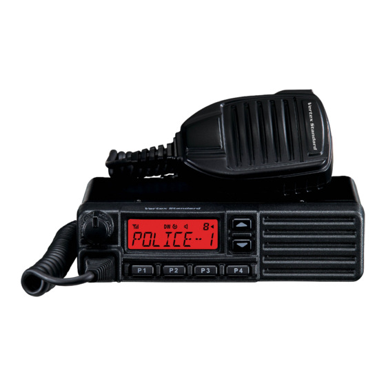
VHF FM Transceiver
VX-2100 Series
VX-2200 Series
Service Manual
VX-2100 Series
Introduction
This manual provides the technical information necessary for servicing the VX-2100/-2200 Series Mobile Transceiver.
Servicing this equipment requires expertise in handing surface-mount chip components. Attempts by non-qualified
persons to service this equipment may result in permanent damage not covered by the warranty, and may be illegal
in some countries.
Two PCB layout diagrams are provided for each double-sided board in this transceiver. Each side of the board is
referred to by the type of the majority of components installed on that side ("Side A" or "Side B"). In most cases one
side has only chip components (surface-mount devices), and the other has either a mixture of both chip and leaded
components (trimmers, coils, electrolytic capacitors, ICs, etc.), or leaded components only.
As described in the pages to follow, the advanced microprocessor design of the VX-2100/-2200 allows a complete
alignment of this transceiver to be performed without opening the case of the radio; all adjustments can be performed
from the personal computer, using with the Vertex Standard FIF-12 USB Programming Interface and CE82 Software.
While we believe the information in this manual to be correct, Vertex Standard assumes no liability for damage that
may occur as a result of typographical or other errors that may be present. Your cooperation in pointing out any
inconsistencies in the technical information would be appreciated.
This transceiver is assembled using Pb (lead) free solder, based on the RoHS specification.
Only lead-free solder (Alloy Composition: Sn-3.0Ag-0.5Cu) should be used for repairs performed on this ap-
paratus. The solder stated above utilizes the alloy composition required for compliance with the lead-free
specification, and any solder with the above alloy composition may be used.
Specifications ............................................................... 2
DSUB 15-pin Accessory Connector .......................... 4
Exploded View & Miscellaneous Parts ................... 5
Parts List ........................................................................ 6
Block Diagram .............................................................. 7
Circuit Description ...................................................... 8
Alignment ................................................................... 10
Installation of Option ............................................... 16
VX-2100/-2200 ( VHF ) Service Manual
Important Note
Contents
Board Units (Schematics & Parts Layout)
MAIN Unit ............................................................. 17
MAIN-2 Unit (50 W: Lot. 33~96) ......................... 35
FRONT-A Unit ( VX-2100 ) .................................... 38
FRONT-B Unit ( VX-2200 ) .................................... 40
Optional Units (Schematics & Parts Layout)
FVP-25 Encryption/DTMF Pager Unit ............... 42
Vertex Standard LMR, Inc.
©
2015 Vertex Standard LMR, Inc.
EC061N90M
VX-2200 Series
1
Advertisement
Table of Contents

Related Manuals for Vertex VX-2100 series


Summary of Contents for Vertex VX-2100 series
-
Page 1: Table Of Contents
Vertex Standard FIF-12 USB Programming Interface and CE82 Software. While we believe the information in this manual to be correct, Vertex Standard assumes no liability for damage that may occur as a result of typographical or other errors that may be present. Your cooperation in pointing out any inconsistencies in the technical information would be appreciated. -
Page 2: Specifications
Specifications: USA(NA) & EXP General Frequency Ranges: 134 -174 MHz Number of Groups: 1 group (VX-2100 Series) 8 groups (VX-2200 Series) Number of Channels: 8 channels (VX-2100 Series) 128 channels (VX-2200 Series) Power Supply Voltage: 13.6 V ± 15% Channel Spacing: 12.5 / 25 kHz... - Page 3 Specifications: EIA(CE) General Frequency Ranges: 134 -174 MHz Number of Groups: 1 group (VX-2100 Series) 8 groups (VX-2200 Series) Number of Channels: 8 channels (VX-2100 Series) 128 channels (VX-2200 Series) Power Supply Voltage: 10.8 - 15.6 V DC Channel Spacing: 12.5 / 20 / 25 kHz...
-
Page 4: Dsub 15-Pin Accessory Connector
DSUB 15-pin Accessory Connector Pin 1: AF IN ( A Pin 6: EXT PTT NALOG NPUT External Microphone Input. Nominal input level is 6 Shorting this port to ground causes the transceiver to mV at 600-ohm. be placed in the Transmit mode, while opening the When connect the External Microphone to this port, connection to this port returns the transceiver to the insert a 0.1 μF coupling capacitor between the micro-... -
Page 5: Exploded View & Miscellaneous Parts
Exploded View & Miscellaneous Parts VX-2100 FRONT PANEL FRONT-A-UNIT CB3472001 RA0790200 TOP CASE RA0787600 RA080360A LIGHT GUIDE (x3 pcs) RA0841400 RUBBER PACKING BLIND SHEET RA078750A HOLDER RA0800600 T9318283A SPONGE RUBBER RA0845300 WIRE ASSY (RED) RUBBER KNOB These nuts are attached to ... -
Page 6: Parts List
Parts List DESCRIPTION VALUE TOL. MFR'S DESIG VXSTD P/N VERSION SIDE LAY ADR PCB with Components MAIN UNIT (w/o Q1009 PA Module) CS2124701 50 W CS2124702 25 W FRONT-A UNIT (VX-2100) CB3472001 FRONT-B UNIT (VX-2200) CB3473001 Mechanical Parts FRONT PANEL ASSY RA079170A VX-2100 FRONT PANEL ASSY RA079160A VX-2200... -
Page 7: Block Diagram
Block Diagram VX-2100/-2200 ( VHF ) Service Manual... -
Page 8: Circuit Description
Circuit Description 1. Circuit Configuration by Frequency 2-4. Audio amplifier Detected signal from Q1036 (NJM2591V) is inputted to The receiver is a double-conversion superheterodyne with Q1042 (LM2902PW) and is output through the band pass a first intermediate frequency (IF) of 67.65 MHz and a filter inside Q1042 (LM2902PW). - Page 9 Circuit Description 3. Transmitter System 4-1. VCO While the radio is receiving, the RX oscillator Q1029 3-1. Mic Amplifier (2SK508) in the VCO generates a programmed frequency There are two micrphone inputs, J1004 (front) and J1006 between 201.65 and 241.65 MHz as 1st local signal. While (D-Sub).
-
Page 10: Alignment
Regulated DC Power Supply (standard 13.6V DC, 15A) ponent replacement and service should be performed only Frequency Counter: ±0.2 ppm accuracy at 200 MHz by an authorized Vertex Standard representative, or the AF Signal Generator warranty policy may be voided. -
Page 11: Test Setup
Alignment Test Setup Basic Alignment Mode Setup the test equipment as shown below, and then ap- The Basic Alignment mode allows you to align the entire ply 13.6V DC power to the transceiver. radio. The value of each parameter can be changed to the desired position by use of the “... - Page 12 Alignment 1. RX VCO Tune Voltage (RX VCO) This parameter is to align the “Tune Voltage” of RX VCO. This alignment will be done automatically between the radio and PC. 1. Press the “Start” button on the “Basic Alignment” win- dow to open the RX VCO Adjustment window.
- Page 13 Alignment 4. RX Sensitivity (RX Tune) This parameter is to align the RX BPF (Band Pass Filter) for Rx sensitivity. It must be done both alignments of the “RX VCO Tune Voltage” and “PLL Reference Frequency” before this alignment is going to start. 1.
- Page 14 Alignment 6. TX Power Open the “Basic2” window, this parameter is to align the Transmit Output (Hi/Low) Power. The factory default is as followings. 50 W model 25 W model High 50 W 25 W Low-High 25 W 12.5 W Low-Middle 10 W E-Low...
- Page 15 Alignment 8. Sub Audio Deviation <CTCSS> / <DCS> This parameter is to align the Deviation of Sub-Audio (CTCSS/DCS). The “TX VCO Tune Voltage” and “Max Deviation” must be done before this alignment is started. 1. Press the “Start” button to start the alignment. 2.
-
Page 16: Installation Of Option
Each optional Unit is easily programmed the configula- tions using a Vertex CE82 programmer with an IBM PC- compatible computer. Figure 1 Figure 3... -
Page 17: Main Unit
MAIN Unit (25 W: Lot. 1~4 / 50W: Lot. 1~4) 67.65MHz RX:1.3V RX:7.4V -121.5dBm -103.0dBm 67.65MHz -81.5dBm RX:8.0V TX:0V TX:0V -123.8dBm (C1046 removed) -111.0dBm (C1146 removed) -108.5dBm -102.5dBm (C1230 removed) TX:0V RX:7.5V RX:2.0V -110.0dBm (C1198 removed) Circuit Diagram TX:0V TX:0V RX:2.0V TX:0V RX:4.3V... - Page 18 MAIN Unit (25 W: Lot. 1~4 / 50W: Lot. 1~4) Parts Layout (Side A) VX-2100/-2200 ( VHF ) Service Manual...
- Page 19 MAIN Unit (25 W: Lot. 1~4 / 50W: Lot. 1~4) Parts Layout (Side B) VX-2100/-2200 ( VHF ) Service Manual...
- Page 20 MAIN Unit (25 W: Lot. 5~8 / 50W: Lot. 5~8) Circuit Diagram VX-2100/-2200 ( VHF ) Service Manual...
- Page 21 MAIN Unit (25 W: Lot. 5~8 / 50W: Lot. 5~8) Parts Layout (Side A) VX-2100/-2200 ( VHF ) Service Manual...
- Page 22 MAIN Unit (25 W: Lot. 5~8 / 50W: Lot. 5~8) Parts Layout (Side B) VX-2100/-2200 ( VHF ) Service Manual...
- Page 23 MAIN Unit (25 W: Lot. 9~17 / 50W: Lot. 9~17) Circuit Diagram VX-2100/-2200 ( VHF ) Service Manual...
- Page 24 MAIN Unit (25 W: Lot. 9~17 / 50W: Lot. 9~17) Parts Layout (Side A) VX-2100/-2200 ( VHF ) Service Manual...
- Page 25 MAIN Unit (25 W: Lot. 9~17 / 50W: Lot. 9~17) Parts Layout (Side B) VX-2100/-2200 ( VHF ) Service Manual...
- Page 26 MAIN Unit (25 W: Lot. 18~20 / 50W: Lot. 18~20) Circuit Diagram VX-2100/-2200 ( VHF ) Service Manual...
- Page 27 MAIN Unit (25 W: Lot. 18~20 / 50W: Lot. 18~20) Parts Layout (Side A) VX-2100/-2200 ( VHF ) Service Manual...
- Page 28 MAIN Unit (25 W: Lot. 18~20 / 50W: Lot. 18~20) Parts Layout (Side B) VX-2100/-2200 ( VHF ) Service Manual...
- Page 29 MAIN Unit (25 W: Lot. 21~96 / 50W: Lot. 21~32) Circuit Diagram VX-2100/-2200 ( VHF ) Service Manual...
- Page 30 MAIN Unit (25 W: Lot. 21~96 / 50W: Lot. 21~32) Parts Layout (Side A) VX-2100/-2200 ( VHF ) Service Manual...
- Page 31 MAIN Unit (25 W: Lot. 21~96 / 50W: Lot. 21~32) Parts Layout (Side B) VX-2100/-2200 ( VHF ) Service Manual...
- Page 32 MAIN Unit (25 W: Lot. 97~ / 50W: Lot. 97~) Circuit Diagram 50 W 25 W C 1003 5.6 p 6.8 p C 1011 12 p 10 p C 1022 22 p ----- C 1036 ----- 12 p C 1043 12 p ----- C 1357...
- Page 33 MAIN Unit (25 W: Lot. 97~ / 50W: Lot. 97~) Parts Layout (Side A) VX-2100/-2200 ( VHF ) Service Manual...
- Page 34 MAIN Unit (25 W: Lot. 97~ / 50W: Lot. 97~) Parts Layout (Side B) VX-2100/-2200 ( VHF ) Service Manual...
-
Page 35: Main-2 Unit (50 W: Lot. 33~96)
MAIN-2 Unit (50 W: Lot. 33~96) Circuit Diagram VX-2100/-2200 ( VHF ) Service Manual... - Page 36 MAIN-2 Unit (50 W: Lot. 33~96) Parts Layout (Side A) VX-2100/-2200 ( VHF ) Service Manual...
- Page 37 MAIN-2 Unit (50 W: Lot. 33~96) Parts Layout (Side B) VX-2100/-2200 ( VHF ) Service Manual...
-
Page 38: Front-A Unit ( Vx-2100 )
FRONT-A Unit (VX-2100) Circuit Diagram RX: 0V TX: 4.9V RX: 4.9V TX: 0V 5.0V 13.6V VX-2100/-2200 ( VHF ) Service Manual... - Page 39 FRONT-A Unit (VX-2100) Parts Layout (Side A) Parts Layout (Side B) VX-2100/-2200 ( VHF ) Service Manual...
-
Page 40: Front-B Unit ( Vx-2200 )
FRONT-B Unit (VX-2200) Circuit Diagram RX: 0V TX: 4.9V RX: 4.9V TX: 0V DIMMER LEVEL 3: 4.8V 5.0V 5.0V VX-2100/-2200 ( VHF ) Service Manual... - Page 41 FRONT-B Unit (VX-2200) Parts Layout (Side A) Parts Layout (Side B) VX-2100/-2200 ( VHF ) Service Manual...
-
Page 42: Fvp-25 Encryption/Dtmf Pager Unit
FVP-25 Encryption/DTMF Pager Unit (Option) Circuit Diagram Parts Layout Side A Side B VX-2100/-2200 ( VHF ) Service Manual... -
Page 43: Fvp-36 Voice Inversion Type Encryption Unit
FVP-36 Voice Inversion Type Encryption Unit (Option) Circuit Diagram Parts Layout Side A Side B VX-2100/-2200 ( VHF ) Service Manual... - Page 44 No portion of this manual may be reproduced without the permission of Vertex Standard LMR, Inc. Vertex Standard is a trademark of Vertex Standard LMR, Inc. All other trademarks are the property of their respective owners. ©2015 Vertex Standard LMR, Inc.