Table of Contents
Advertisement
Advertisement
Table of Contents

Related Manuals for Crest Audio V12


Summary of Contents for Crest Audio V12
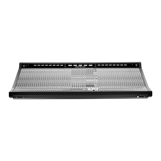
- Page 1 V12 mixing console...
-
Page 2: Mono Input Module
mono input module direct output features This section is intended for use in Front of House operations to provide a controlled feed to an external tape machine. It may also be used as a localized effects send or monitor output. When the console is being used for monitor mixing operations, this output is used as a dedicated send to the Matrix section to generate custom versions of the Matrix mix for monitor use by secondary artists such as horn sections or backing vocals. - Page 3 mono input module group assignment features discrete group assignment switches 1–8 Assignment of post fader signal to discrete group buses unless the pan switch is activated, in which case the signal is post pan pot. When the mode switch within the Direct Output section is depressed, the signal source disconnects from the channel’s main fader and instead obtains its signal from the set of controls located above the assignment section.
- Page 4 mono input module input features pad switch Inserts a 26dB pad into the microphone input circuit. 48-volt phantom power switch Supplies 48 Volts to the microphone input. Will not operate if Line Input is selected. line input switch Selects the line input circuitry using both the XLR and 1/4” phone jack. If a connector is plugged into the 1/4”...
- Page 5 mono input module EQ features high-pass filter on-switch Turn on High Pass filter circuitry. continuously-variable high-pass filter control Sweep control variable between 20Hz and 400Hz at a -18dB per octave rate. high-frequency Q-control with shelf-switch Adjust the Q of the high frequency section between 3.0 (Full Counter Clockwise) and 0.7 (Clockwise).
- Page 6 mono input module aux features aux send section 9/10, 11/12, 13/14, 15/16 Four sets of dual concentric controls, each set having the following associ- ated controls: pre-fader switch Selects the source of the signal for the dual concentric pair between the normal post fader signal source to a pre fader signal source.
- Page 7 mono input module aux features aux send section 5, 6, 7, 8 Four rotary controls, each having the following associated controls: pre-fader switch Individual switches for each aux send selects the source of the signal between the normal post fader signal source position to a pre fader signal source position.
- Page 8 mono input module monitor features 8-segment channel meter Monitors a pre or post fader signal level as determined by a Master Global POST switch within the master section of the console. Normally, a pre fader signal is monitored. When the Global master switch is depressed,ALL channel meters switch to a post fader monitor position to prevent confusion between pre and post channel metering.
- Page 9 p. 9...
-
Page 10: Stereo Input Module
stereo input module direct output features This section is intended for use in Front of House operations to provide a controlled feed of the modules separate left and right signals to an exter- nal tape machine. It may also be used as a localized effects send or moni- tor output. - Page 11 stereo input module group assignment features discrete group assignment switches 1–8 When the mode switch within the Direct Output section is depressed,the stereo signal source disconnects from the channel’s post-fader point and instead obtains its signal from the set of stereo controls located above the assignment section.
- Page 12 stereo input module input features pad switch Inserts a 26dB pad into the left and right microphone input circuit. 48-volt phantom power switch Turns 48 Volts on to the microphone inputs. Will not operate if Line Input is selected. line input switch Inserts a 26dB pad in to the input paths and disables the phantom power.
- Page 13 stereo input module EQ features high-pass filter on-switch Turn on High Pass filter circuitry. continuously-variable high-pass filter control Sweep control variable between 20Hz and 400Hz at a 18dB per octave rate. high-frequency Q-control with shelf-switch Adjust the Q of the high frequency section between 3.0 (Full Counter Clockwise) and 0.7 (Clockwise).
- Page 14 stereo input module aux features aux send section 9/10, 11/12, 13/14, 15/16 Four sets of dual concentric controls, each set having the following associ- ated controls: note: Aux send 9 thru 16 are always fed as stereo: left source feeds auxes 9, 11, 13, 15 right source feed auxes 10, 12, 14, 16 this remains true for pre or post signals.
- Page 15 stereo input module aux features aux send section 5, 6, 7, 8 Four rotary controls, each having the following associated controls: pre-fader switch Individual switches for each aux send selects the source of the signal between the normal post fader signal or a pre fader signal. push-on/push-off switch Control pot acts as an On/Off switch for the associated auxiliary send.
- Page 16 stereo input module monitor features dual 8-segment channel meter Separately monitors a left and right pre or post fader signal level as deter- mined by a Master Global POST switch within the master section of the console. Without this switch depressed, a pre fader signal is monitored. When the Global master switch is depressed,ALL channel meters switch to a post fader monitor position to prevent confusion between pre and post channel metering.
- Page 17 p. 17...
- Page 18 group output module p. 18 —matrix, aux, group mono-matrix features This section is intended for use in Front of House operations to provide a matrixed mix to dedicated locations. When the console is being used for monitor mixing operations, this section can be used as a matrixed mix to feed generic mixes to various stage locations.
- Page 19 group output module —matrix, aux, group mono-matrix features external-in signal-level to matrix Controls level of signal present on XLR input connector on each matrix module. It is this input that allows for customizing of backing artists gener- ic mixes as this input can represent an artists individual microphone input. UPPER CONTROL SECTION (Default Matrix Control) illuminated mute-switch Controls local mute function of this output section - Default is matrix...
- Page 20 group output module p. 20 —matrix, aux, group mono-matrix features insert on-switch Activates Insert return connector. Signal is always fed to balanced insert send connector. peak and signal-present LED Dual color LED monitors the pre fader signal level and pre/post fader clip levels.
- Page 21 group output module —matrix, aux, group mono-matrix features Mtx master and GRP master LED indicators Indicates the operation of this set of controls within this output section. When the MTX MASTER LED (red) is illuminated, ALL of the controls within this Upper Control Section will affect the matrix output. If the GRP MASTER LED (Group) is illuminated (Only one LED will be illuminated), ALL of the controls within this Upper Control Section will affect the group output and feed to the Group Assignment section.
- Page 22 group output module p. 22 —matrix, aux, group aux master features illuminated mute-switch Controls local mute function of this output section - Default is matrix channel output. This switch illuminates red when this section is muted (Regardless of source). µ-mute switch Sets and indicates microprocessor mute preset status.
- Page 23 group output module —matrix, aux, group aux master features solo switch Will illuminate when manually selected in one of the consoles many Solo modes. Controls within the master section determine if this switch will sample signal pre or post level control. Additional switches will determine the operating characteristics of the Solo system.
- Page 24 group output module p. 24 —matrix, aux, group group-assignment features This section always receives its signal from any output block acting as the Group Master Output. This may be the default Lower fader section or the mid or upper control sections as indicated by LED status indicator locat- ed within the individual output block sections.
- Page 25 group output module —matrix, aux, group group-master features illuminated mute-switch Controls local mute function of this output section - Default as matrix channel output. This switch illuminates red when this section is muted (Regardless of source). µ-mute switch Sets and indicates microprocessor mute preset status. This illuminated switch will show current µ...
- Page 26 group output module p. 26 —matrix, aux, group group-master features solo switch Will illuminate when manually selected in one of the consoles many Solo modes. Controls within the master section determine if this switch will sample signal pre or post level control. Additional switches will determine the operating characteristics of the Solo system.
- Page 27 group output module —matrix, aux, group module swap features mode switch (recessed) Controls the assignment of output functions between the three output blocks. This switch toggles between FOH (Front of House) and MONI- TOR (AUX) operation of the lower fader area. When Monitor (Aux) is selected, the middle control section of the module takes over Group Operation.
- Page 28 group output module —matrix, aux, group group rear-panel connectors Always as labeled - Not affected by mode switch. MATRIX OUTPUT CONNECTOR - XLR Balanced INSERT SEND AND RETURN MATRIX CONNECTORS - SEPARATE 1/4” Balanced Send and Return connectors. EXTERNAL MATRIX INPUT CONNECTOR - XLR Balanced AUX (MONITOR) OUTPUT CONNECTOR - XLR Balanced INSERT SEND AND RETURN Aux CONNECTORS - SEPARATE 1/4”...
- Page 29 vca masters VCA MASTER FADER BAY MODULE FUNCTIONS illuminated mute-switches (12) Controls mutes of input channels assigned to the particular VCA Group. Internal jumper select between a input channel mute function (default) or as a VCA channel pull down. 100mm faders (12) Very high quality conductive plastic fader are used in a 6 panel space area with double spacing (2 faders per standard channel width) A master DC voltage is generated and controlled by each VCA master section to con-...
- Page 30 group output module p. 30 —matrix, aux, group LEFT/RIGHT/MONO MASTER FADER BAY MODULE FUNCTIONS illuminated mute-switches (3) Controls mutes of main outputs. output mute safe switch Disables the Left, Right, and Mono Mute switches to prevent accidental activation during a performance. 100mm faders 3 Individual Left, Right, and Mono (Center) high quality conductive plastic faders are used.
- Page 31 input fader block LOWER MODULE CONSTRUCTION act LED (µ-mute) This red LED lites whenever a Mute command is issued from the Micro. This can be from any of the Sequenced or Manual Mute Scenes or from a received MIDI Note command.Whether or not the channel responds to that mute command is determined by the status of two SAFE switches:the global Input Micro Safe switch (near master faders), or the channel Mute Safe switch.
- Page 32 stereo matrix / aux out module stereo-matrix features This section is intended for use in Front of House operations to provide a matrixed stereo mix to dedicated locations. When the console is being used for monitor mixing operations,this section can be used as a matrixed stereo mix to feed generic mixes to various stage locations.
- Page 33 stereo matrix / aux out module stereo-matrix features external-in left and right signal-level to matrix Dual Concentric level control pair with center controlling left XLR line input to left matrix output and the outside controlling the right XLR line input to the right matrix output. It is this set of inputs that allows for cus- tomizing of backing artists generic mixes, as these inputs can represent an artists microphone inputs.
- Page 34 stereo matrix / aux out module p. 34 stereo-matrix features mtx to aux When this switch is depressed, a post stereo matrix level signal is fed to the modules left and right Aux (Monitor) mix buses. An internal jumper allows the matrix to be sourced pre fader if desired. This allows generic mixes such as drums to be able to be mixed with the primary aux moni- tor outputs.
- Page 35 stereo matrix / aux out module dual-aux output features This section controls aux outputs number 9 through 16. It is intended to operate as individual aux outputs, or when the module’s stereo mode switch is depressed, as a stereo output. In stereo configuration, this out- put par may be used to generate dedicated broadcast or cart machine feeds, or when used as a monitor console, to generate stereo wedge or “In the Ear”...
- Page 36 stereo matrix / aux out module dual-aux output features talkback preset-switch (one odd channel, one even channel) When selected will allow the Master Talkback Switch and system to access this particular output. µ-mute switch Sets and indicates microprocessor mute preset status. This illuminated switch will show current µ...
- Page 37 stereo matrix / aux out module dual-aux output features solo switch Will illuminate when manually selected in one of the consoles many Solo modes. Controls within the master section determine if this switch will sample signal pre or post level control. Additional switches will determine the operating characteristics of the Solo system.
- Page 38 master modules p. 38 —M1, M2 oscillator features pink-noise switch When depressed will generate Pink Noise in place of a sine wave signal as the signal generator output. 10kHz, 1kHz, 100Hz switches Selects the center point of the oscillator frequency control pot. frequency control Will adjust frequency output of the section over a 10 to 1 range with the center frequency chosen with the above switches.
- Page 39 master modules —M1, M2 meter-view features meters-A/meters-B switch bank (One set per module - Left master module switch bank controls left 8 meters, Right master module switch bank controls right 8 meters) GROUP 1-8 AUX 1-8 AUX 9-16 MTX 1-8 MTX 9-16 Interlocking switches selects the display function of the left or right meter banks.
- Page 40 master modules p. 40 —M1, M2 alternate output features Alternate output A-B are located on the left master module and Alternate output C-D are located on the right master module. Controls provided on the left and right module alternate outputs are identical. This section is intended for miscellaneous signal outputs including dressing room feeds, broadcast production monitor feeds, sub output feeds, delay speaker stacks, back of stage feeds, etc.
- Page 41 master modules —M1, M2 alternate output features solo switch Will illuminate when manually selected in one of the consoles many Solo modes. Controls within the master section determine if this switch will sample signal pre or post level control. The SOLO system is designed that if the Alternate output is soloed, it will display its contents on the Solo meters, but it will not feed Solo signal to the Alternate output section, avoiding a potential source of a feedback loop.
- Page 42 master modules p. 42 —M1, M2 talkback master features group talkback master-switch Allows talkback to all group outputs that have their talkback preset switch selected when the MASTER Talkback switch is depressed. No communi- cations is permitted to Group Outputs unless this master switch is depressed.
- Page 43 master modules —M1, M2 intercom interconnect features The console is designed to interconnect with a ClearCom compatible intercom system. Three-pin male and female XLR’s are located on the console rear-panel for intercom hookup and loop-thru.A separate four pin XLR connector is located under the arm rest for connection to a standard intercom headset.
- Page 44 master modules p. 44 —M1, M2 monitor output features MONITOR OUTPUT CONNECTORS - XLR balanced line level outputs on the rear panel plus 1/4” headphone connector under the arm rest area with a hinged cover preventing confusing with the regular headphone sys- tem.
- Page 45 master modules —M1, M2 monitor output features Combines the Left and Right signals into a summed mono signal with the same signal appearing on the left and right output connectors and in head- phones. Drops the XLR signal output level by 20db while depressed. 100mm fader level-control Adjust output level of the monitor output.
- Page 46 master modules p. 46 —M1, M2 headphone output features HEADPHONE OUTPUT CONNECTORS - 1/4” headphone connector under the arm rest area as well as on the top module panel. HEADPHONE INSERT CONNECTORS - Separate left and right insert send and return connectors for the purpose of inserting external delay devices.
- Page 47 master modules —M1, M2 headphone output features solo defeat Normally the Solo system will override any monitor switches that have been selected. When the Solo Defeat switch is selected, no solo signal will appear on headphones. on-switch Turns on the headphone output. The prevents leakage of headphone sig- nal to noise sensitive rooms by being able to turn off headphones before they are removed.
- Page 48 master modules p. 48 —M1, M2 solo system features solo-clear switch When any input or output solo switch is active, depressing the SOLO CLEAR switch will cancel all soloed channels. When in Input Priority mode, this switch will only cancel only input channel solo functions. solo-select switch Will select operation of the solo system to monitor either pre fader sig- nals or post fader/post pan pot signals.
- Page 49 p. 49...
- Page 50 micro mute system p. 50 micro panel features The V-12 is equipped with a microprocessor based muting and control sys- tem.This system allows the operator to control the channel and output mutes of the console using pre-set manual mute scenes, pre-programmed sequenced scenes or through MIDI based external sequencers.The V-12 micro system can also be configured to send MIDI Show Control com- mands.
- Page 51 micro mute system micro panel features manual mute-bank select When this button is held down, the lower display shows the current Manual Mute bank. Using the Scroll Keys along with this button, the bank can be changed to any one of the twelve possible. An asterisk (*) will show in the last position of the display to indicate a changed bank.
- Page 52 micro mute system p. 52 channel fader features µ-button This momentary switch is used to program the channel mutes when the Micro is in EDIT Mode. Pressing this switch will assign/un-assign it to a mute scene (either Sequenced or Manual), the internal yellow LED will blink to show an assignment.The operator uses these blinking LEDs to review the mute pattern being edited.These buttons are also used to send MIDI mute info when the Micro is in normal operation mode and MIDI Mutes is ON (see Utility).
-
Page 53: Mute Button
micro mute system channel fader features VCA LED (on module) This LED glows green to indicate the amount of control voltage applied to the channel VCA; the greater the control voltage, the brighter the LED. Often, a channel may be assigned to more than one VCA master, and it is easy to overlook an assignment and wonder why a channel isn’t on.This LED gives the operator a quick reference to the state of the channel VCA;if there is no LED indication,there is no VCA control voltage.The LED will turn from... -
Page 54: Normal Operation Mode
micro mute system p. 54 micro operation normal operation mode These switches are normally lit and available for use. GO Switch BANK SELECT Scroll UP Scroll DOWN 1 of 3 from Next Scene: Mute(default), Pgm, Chan Upper Display shows Next Scene and Lower display shows Active Scene. Both displays show data in the following format : mmm ppp cc mmm= Scene # [001 to 128] ppp=... - Page 55 micro mute system Select Scene to edit Press EDIT/PREV key- It starts blinking indicating Edit Mode. Next Scene is the default Edit selection: MUTE (Next Scene) begins blinking. Any Chan or Outputs assigned to that Next Scene Mute- their µ-Mutes begin blinking.
- Page 56 micro mute system p. 56 addition destinations are desired for the same copy data, additional copy/paste cycles are required. To copy a mute pattern, press the lit COPY key. CLEAR turns off ,the PASTE sw comes on,the selected edit Mute lite goes from Blink to steady on.
- Page 57 micro mute system Exiting Edit Mode The normal way to exit from Edit Mode is to Press the blinking EDIT key. The Console returns to Normal Operation Mode: Other ways to exit Edit Mode: If editing Next Scene(Mute/Pgm/Chan):Pressing GO puts the edited scene into Active Scene and then does a normal exit from Edit Mode into Operation Mode.Any * in the Next Scene display are maintained and also transferred to the Active Scene.This exit actually doesn’t change the data...
- Page 58 micro mute system p. 58 If an Active Scene had been edited and then RECALL LAST is pressed, the edited Active Scene is transferred up to the Next Scene display.The only thing that could have been edited on the Active Scene was the mute pat- tern.
- Page 59 micro mute system Clear Utilities CLR_SEQ_MT PRESS_CLR CLR_SEQ_PC PRESS_CLR CLR_MM_BNK PRESS_CLR CLR_MM_ALL PRESS_CLR Show Control SHOW_CTRL OFF ON General Controls BRIGHTNESS BRIGHT_=_5 1-7 REV_LEVEL REV_0.94 Micro Utilities MAIN_MICRO MAN_MUTES SEQ_SCENES SCENE_OPER CUMULATIVE SINGLE_MAN RPD_RECALL TO_NEXT PASSWORD SET_PSWORD UTILITY DETAILS MIDI Utilities MIDI CHAN Sets Default MIDI Channel –Used for MIDI Mutes, PgmChng and Dump.
- Page 60 micro mute system p. 60 MIDI Note info received on correct MIDI chan controls Chan mutes(for play- back from MIDI sequencer) Note info sent or received MIDI LOAD Reloads Mute Scenes & Manual Mutes. Uses Sysex command for dump and load. MIDI DUMP Dumps all 128 Mute Scenes and all banks of Manual Mutes.
- Page 61 micro mute system SINGLE_MAN 2 of 13 Scenes possible: 1 of 12 Manual Mutes and Seq Scene Micro Utilities MAIN MICRO If set to OFF, completely disables Micro section. Both dis- plays and all buttons are turned off. Note: If this setting is selected, upon exiting Util Mode, the micro will appear to be non-functioning.
- Page 62 micro mute system p. 62 when he scrolls to PASSWORD again before leaving the Utility Mode. Press CLEAR to clear the password to Off. RESETTING THE MICRO: The V-12 micro is designed for reliable, trouble-free operation , but it is, after all, a computer.There may be situations where it misbehaves. If this occurs, a reset is probably the best course of action.There are two types of reset: a normal, maintained reset;...
- Page 63 p. 63...
- Page 64 V12 rear views...
- Page 66 V12 rear views...