
Related Manuals for SMC Networks ex250-sen1


Summary of Contents for SMC Networks ex250-sen1
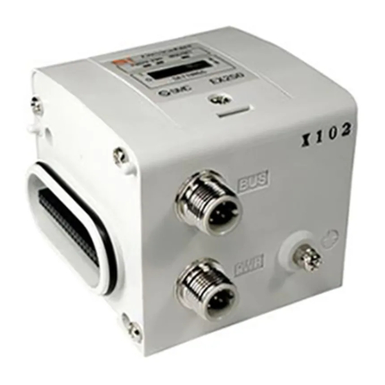
- Page 1 No.EX##-OMK0004-A PRODUCT NAME SI unit for EtherNet/IP MODEL / Series / Product Number EX250-SEN1...
-
Page 2: Table Of Contents
Table of Contents Safety Instructions Product Summary Definition and terminology Model Indication and How to Order Summary of Product Parts Mounting and Installation Installation Position of end plate Wiring LED Indication and Settings EtherNet/IP CONFIGURATION WITH RSLogix5000 Maintenance Troubleshooting Specifications Specifications Dimensions Option... -
Page 3: Safety Instructions
Safety Instructions These safety instructions are intended to prevent hazardous situations and/or equipment damage. These instructions indicate the level of potential hazard with the labels of "Caution", "Warning" or "Danger". They are all important notes for safety and must be followed in addition to International ∗1) standards (ISO/IEC) and other safety regulations. - Page 4 Caution The product is provided for use in manufacturing industries. The product herein described is basically provided for peaceful use in manufacturing industries. If considering using the product in other industries, consult SMC beforehand and exchange specifications or a contract if necessary. If anything is unclear, contact your nearest sales branch.
- Page 5 Operator ♦This operation manual is intended for those who have knowledge of machinery using pneumatic equipment, and have sufficient knowledge of assembly, operation and maintenance of such equipment. Only those persons are allowed to perform assembly, operation and maintenance. ♦Read and understand this operation manual carefully before assembling, operating or providing maintenance to the product.
- Page 6 ■NOTE ○Follow the instructions given below when designing, selecting and handling the product. •The instructions on design and selection (installation, wiring, environment, adjustment, operation, described below must also be followed. maintenance, etc.) ∗Product specifications •When conformity to UL is required, the SI unit should be used with a UL1310 Class 2 power supply. •The SI unit is a approved product only if they have a mark on the body.
- Page 7 •Do not use the product in an environment where corrosive gases or fluids could be splashed. Otherwise damage to the product and malfunction can result. •Do not use in an area where surges are generated. If there is equipment which generates a large amount of surge (solenoid type lifter, high frequency induction furnace, motor, etc.) close to the SI unit, this may cause deterioration or breakage of the internal circuit of the SI unit.
-
Page 8: Product Summary
Product Summary System configuration This system realizes the reduce wiring between the input and output equipment by connecting to EtherNet/IP EtherNet/IP and the input and output equipment communicate through the SI unit. Up to 32 inputs can be connected to the SI unit using Input blocks. ∗... -
Page 9: Definition And Terminology
■Definition and terminology Terms Definition 100BASE-TX Standard of LAN transmission route with a transmission speed of 100 Mbps. A protocol to automatically set the information to be registered in individual equipment DHCP connected with a TCP/IP network in order to use the network. This includes the IP address. -
Page 10: Model Indication And How To Order
Model Indication and How to Order Summary of Product Parts Part names Application ∗ 1 Communication connector Connect the EtherNet/IP line. ∗ 1 Power supply connector Supplies power to the solenoid valve, Output block, SI unit and Input block. Input block connector Connects the Input block. -
Page 11: Mounting And Installation
Mounting and Installation ■Installation The SI unit does not have mounting holes, so it cannot be installed alone. Make sure to connect the solenoid valve. When an input block is not required, connect the end plate directly to the SI unit. ○Installation example 55.5 76.5... -
Page 12: Position Of End Plate
■Position of end plate •Be sure to connect the end plate (on the Input block side) at the left end of the manifold. •When the valve is not connected, be sure to connect the end plate R (on the Output block side) at the right end of the manifold. -
Page 13: Wiring
■Wiring 1. Communication wiring Connect the Ethernet communication cable to the communication connector of SI unit. Cable connection 1) Aligning the key groove with the communication connector (4-pin, socket) of SI unit, plug the Ethernet communication cable (plug). 2) Tighten the lock nut on the cable side by turning it clockwise by hand. 3) Confirm that the connector does not move. - Page 14 2. Power supply wiring Connect the power supply cable to the power supply connector of SI unit. When selecting the power supply, refer to "Safety Instructions" (page 5) in this manual. Cable connection 1) Aligning the key groove with the power supply connector (plug) of SI unit, plug the power supply cable (socket).
- Page 15 Connecting one or two power supplies to SI Unit Both of single power supply and two power supply systems can be adopted, however, the wiring should be made separately (for solenoid valves/output and for input and control) for both systems. A.
-
Page 16: Led Indication And Settings
LED Indication and Settings ○LED indication Display Contents Insufficient power supply for solenoids Green light ON Normal power supply for solenoids Insufficient power supply for input and control Green light ON Normal power supply for input and control The power supply for control is OFF Green light ON Operating normally Green flashes... - Page 17 ○Switch settings Open the switch protective cover and set the switches with a sharp-pointed watchmakers screwdriver etc. NOTE 1. Be sure to turn off the power supply before setting the switches. 2. Be sure to set these switches before use. 3.
- Page 18 ∗1: Remote control (SW1 Dip switches 1-4 off) SMC's EX250 SI Unit will respond to the following Rockwell Automation BOOTP/DHCP Server commands. Enable DHCP Selecting this function will enable the EX250 SI Unit to retrieve its boot information from the BOOTP/DHCP Server. If DHCP is enabled the EX250 SI Unit will retrieve its boot information during the next power up.
-
Page 19: Ethernet/Ip Tm Configuration With Rslogix5000
EtherNet/IP CONFIGURATION WITH RSLogix5000 When setting up the node with RSLogix5000 , specific values must be entered for the assembly instance with regards to Input, Output and Configuration. Please see the diagram below for a Rockwell Automation’s RSLogix5000 programming software example. ∗: PLC software RSLogix5000 manufactured by Rockwell Automation is shown above. -
Page 20: Maintenance
Maintenance How to replace SI unit •Remove screws mounted on the end plate, and separate it from the valve unit. •Replace the SI unit (Tie-rods should not be removed). Mount the removed end plate, and tighten it with the same screws with specified tightening torque. (0.6 Nm) Precautions on maintenance (1) Be sure to check that all the power supply is turned off. -
Page 21: Troubleshooting
Troubleshooting Troubleshooting flow chart If the SI unit malfunctions, select the specific trouble with the flow chart stated below. A reduced wiring system does not operate normally A solenoids valve The SI unit Refer to Refer to Only the solenoid does not operate PWR_LED goes off trouble No.1... - Page 22 Trouble Trouble No.1 Trouble Possible cause Investigation method of cause Remedy Only the Check the troubleshooting for the solenoid Correct the trouble of the solenoid valve Solenoid valve failure valve. solenoid valve. LED lights up Trouble No.2 Trouble Possible cause Investigation method of cause Remedy The outputs...
- Page 23 Trouble No.3 Trouble Possible cause Investigation method of cause Remedy Check that the output load cable is not Review the connecting broken, and that the connection between condition of the output load. the output load and connector has not (If the cable is broken, Incorrect connection loosened.
- Page 24 Trouble No.5 Trouble Possible cause Investigation method of cause Remedy Failure of the power Supply 24 VDC ±10% to the Check the supply voltage to the power supply for the input supply for the input and control of the SI power supply for the input and control of the SI unit.
- Page 25 Trouble No.8 Trouble Possible cause Investigation method of cause Remedy Check that the power supply cable for the Review the connection solenoid valve and output is not broken, Incorrect wiring for the condition of the power supply and that the connection between the power power supply for cable.
- Page 26 Trouble No.12 Trouble Possible cause Investigation method of cause Remedy The green SI Review the setting of the SI unit MS_LED Setting error. Check the setting of the SI unit. unit. flashes. Trouble No.13 Trouble Possible cause Investigation method of cause Remedy The SI unit Review the setting of IP...
-
Page 27: Specifications
Specifications ■Specifications General specification Item Specification Operating ambient temp. 5 to 45 Operating ambient humidity 35 to 85%RH (No dew condensation) Storage ambient temp. -20 to +60 Withstand voltage 500 VAC for 1 min. Insulation resistance 500 VDC 10 MΩ or more Operating environment No corrosive gas Pollution degree... - Page 28 I/O mapping Input area mapping Input data Offset (word) Sensor input area L: Fixed to Low Status input area Diagnostic (Status input area) Item Status Condition No supply voltage Status of solenoid power supply Supply voltage OK Short circuit Status of sensor power supply Normal Output area mapping Output data...
- Page 29 ○Output No. assignment Combinations of output data and valve manifold ∗: Output No. starts from 0, and will be assigned to the valves in order from the SI unit mounted side. ∗: Manifold wiring is double wired as standard ("double wiring specification"), and the output numbers are assigned in order from A side to B side.
-
Page 30: Dimensions
■Dimensions -29- No.EX##-OMK0004-A... -
Page 31: Option
Option 1. Ethernet communication cable For details, refer to subsection "Wiring" (page 12) in this manual. Hot to order 2. Power supply cable For details, refer to subsection "Wiring" (page 13) in this manual. Hot to order 3. Spare fuse (for Input block) Hot to order 4. - Page 32 5. Power supply cable (for power input connector of Power block) Hot to order 6. Power supply cable (for power supply connector of Power block) Hot to order 7. Input block relay connector cable Hot to order 8. Input block assembly type connector Hot to order -31- No.EX##-OMK0004-A...
- Page 33 9. End plate (Input block side) Hot to order Accessory Hexagon thin socket head bolt (2 pcs.) 10. End plate R (Output block side) Hot to order 11. Waterproof cap Mounted on the unused ports of the Input block, Output block and Power block. Proper use of this waterproof cap can achieve IP67 enclosure.
- Page 34 Revision history A: Add some contents. Note: Specifications are subject to change without prior notice and any obligation on the part of the manufacturer. EtherNet/IP is a trademark of ODVA. © 2007-2012 SMC Corporation All Rights Reserved No.EX##-OMK0004-A...