Table of Contents
Advertisement
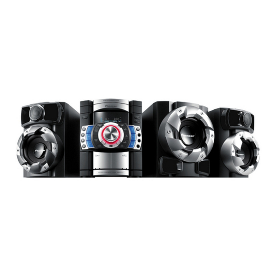
DVD MINI COMPONENT SYSTEM
X-RSM400DV
THIS MANUAL IS APPLICABLE TO THE FOLLOWING MODEL(S) AND TYPE(S).
Model
Type
X-RSM400DV
LXCN
DXCN
X-RSM400DV
DXCNRI
X-RSM400DV
For details, refer to "Important Check Points for good servicing".
PIONEER CORPORATION
PIONEER ELECTRONICS (USA) INC. P.O. Box 1760, Long Beach, CA 90801-1760, U.S.A.
PIONEER EUROPE NV Haven 1087, Keetberglaan 1, 9120 Melsele, Belgium
PIONEER ELECTRONICS ASIACENTRE PTE. LTD. 253 Alexandra Road, #04-01, Singapore 159936
PIONEER CORPORATION
Power Requirement
AC 110 V to 240 V
AC 110 V to 240 V
AC 110 V to 240 V
4-1, Meguro 1-chome, Meguro-ku, Tokyo 153-8654, Japan
2009
X-RSM400DV
DVD
Serial No.
Region No.
3
&&&&######LE
4
&&&&######ME
2
&&&&######RB
ORDER NO.
RRV4011
Remarks
LE : ASEAN
ME : LATIN AMERICA
RB : MIDDLE EAST
T-ZZV NOV.
2009 Printed in Japan
Advertisement
Table of Contents

Related Manuals for Pioneer x-rsm410dvh


Summary of Contents for Pioneer x-rsm410dvh
- Page 1 PIONEER CORPORATION 4-1, Meguro 1-chome, Meguro-ku, Tokyo 153-8654, Japan PIONEER ELECTRONICS (USA) INC. P.O. Box 1760, Long Beach, CA 90801-1760, U.S.A. PIONEER EUROPE NV Haven 1087, Keetberglaan 1, 9120 Melsele, Belgium PIONEER ELECTRONICS ASIACENTRE PTE. LTD. 253 Alexandra Road, #04-01, Singapore 159936...
- Page 2 LASER DIODE CHARACTERISTICS For DVD Wave Length: 656 nm Operating output: 0.1 mW CW, Class 1 Maximum output: Class 1 For CD Wave Length: 789 nm Operating output: 0.15 mW CW, Class 1 Maximum output: Class 1 X-RSM400DV...
- Page 3 [Important Check Points for Good Servicing] In this manual, procedures that must be performed during repairs are marked with the below symbol. Please be sure to confirm and follow these procedures. 1. Product safety Please conform to product regulations (such as safety and radiation regulations), and maintain a safe servicing environment by following the safety instructions described in this manual.
- Page 4 SECTION 5. DIAGNOSIS CONNECTION ………………………...….…..……………..
-
Page 5: Notes Regarding Handling Of The Pick-Up
SECTION 1. GENERAL SERVICING PRECAUTIONS NOTES REGARDING HANDLING OF THE PICK-UP 1. Notes for transport and storage 1) The pick-up should always be left in its conductive bag until immediately prior to use. 2) The pick-up should never be subjected to external pressure or impact. Storage in conductive bag Drop impact 2. -
Page 6: Notes Regarding Compact Disc Player Repairs
NOTES REGARDING COMPACT DISC PLAYER REPAIRS 1. Preparations l l e nents are sensitive to, and easily affected by, static electricity. If such static electricity is high voltage, components can be damaged, and for that reason components should be handled with care. c i t must be taken, therefore, to avoid repair or storage where the temperature of humidity is high, where strong magnetism is present, or where there is excessive dust. -
Page 7: Safety Precautions
SAFETY PRECAUTIONS Electrostatically Sensitive Devices (ESD) Some semiconductor (solid state) devices can be damaged easily by static electricity. Such components commonly are called Electrostatically Sensitive Devices (ESD). Examples of typical ESD devices are integrated circuits and some field-effect transistors and semiconductor chip components. The following techniques should be used to help reduce the incidence of component damage caused by static electricity. - Page 8 When Option Code Assembly is replaced, perform this Option Code setting. NAME OPT 0 OPT 1 OPT 2 OPT 3 OPT 4 OPT 5 OPT 6 OPT 7 OPT 8 OPT 9 X-RSM400DV/DXCNRI X-RSM400DV/DXCN NAME OPT 0 OPT 1 OPT 2 OPT 3 OPT 4 OPT 5...
- Page 9 PROGRAM DOWNLOAD GUIDE Caution) Do not perform any other work such as disconnecting USB device, switching to the Function and turning off the power while downloading it to the set. The USB device should be disconnected after completing the download. •...
-
Page 10: Specifications
SPECIFICATIONS General Power supply AC 110 V~240 V, 50 Hz/60 Hz Power consumption 65 W External dimensions (WxHxD) 273 x 336 x 372 mm Operating temperature 5 °C to 35 °C Operating humidity 5% to 85 % Tuner FM Tuning Range 87.5 ~ 108.0 MHz AM Tuning Range 530 ~ 1 700 KHz (DXCN), 531 ~ 1 602 KHz (LXCN/DXCNRI) -
Page 17: Speaker Section
4. SPEAKER SECTION (1) FRONT SPEAKER A60L A60R LOCA. NO PART NO. DESCRIPTION SPECIFICATION REMARKS A60L EAB61030301 Speaker Assembly MCS404 049-01368-07 EAW MCS404 A60R Speaker Assembly EAB61030201 MCS404F 049-01368-07 EAW MCS40 2-11... -
Page 18: Passive Subwoofer
(2) PASSIVE SUBWOOFER LOCA. NO PART NO. DESCRIPTION SPECIFICATION REMARKS EAB61030401 Speaker Assembly MCS404W 049-01368-07 EAW MCS40 2-12... -
Page 19: Packing Accessory Section
4. PACKING ACCESSORY SECTION Battery Instruction Ass'y Antenna, Loop (AM) Remote Controller Antenna, T (FM) 811 RCA Cable, 1Pin(Black) 803FT Packing, 803 Packing, Main Set Front Speaker Top 803WT Packing, Woofer Top 804W Bag, Woofer 804F Bag, Front Speaker 804F Bag, Front Speaker 804 Bag, Main Set 803WB Packing, Woofer Bottom... -
Page 20: Packing & Accessory Section
S AL LOCA. NO. PART NO. DESCRIPTION SPECIFICATION REMARKS AKB72913811 Remote Controller Assembly CB1 MDT404 MINI DVD Pioneer CONTRAS T TABLE X-RSM400DV/DXCN, X-RSM400DV/DXCNRI and X-RSM400DV/LXCN are constructed the same except for the following: Ma rk X-RS M400DV/DXCN X-RS M400DV/DXCNRI X-RS M400DV/LXCN... - Page 21 2-12...
-
Page 22: Section 3. Electrical Part
SECTION 3. ELECTRICAL PART AUDIO ELECTRICAL TROUBLESHOOTING GUIDE 1. POWER (SMPS) POWER (SMPS) Check the fuse Replace the fuse F901 Check the DC V of C905 Check BD901, LF901, 902 if DC V is over 400V Check the DC V of C909,C903,C921 Check IC901, 902 Replace IC901,902 If DC V is in 14~19V... -
Page 23: Vkk Check
3. VKK PART CHECK 2. P-SENS VKK CHECK P-SENS Check Check Check power circuit Check power circuit the pin6 of P9702 the pin3 of P9702 troubleshooting troubleshooting if DC V is over if DC V is over 5.6V -28V 4. MICOM PART CHECK I MICOM PART CHECK I Check P-SENS... - Page 24 5. MICOM PART CHECK II MICOM PART CHECK II Refer to SMPS Check P-SENS troubleshooting (P7904_pin6) Check Check both Replace D101 If output of end voltage of D101 D101 is 5V Check If IC103_pin8 and IC100_pin14,40,55,89 are 5V Check D101 X101:32.768KHz X100:9.8304MHz Check the operation...
-
Page 25: Fld Display Check
7. FLD DISPLAY CHECK FLD DISPLAY CHECK Check CN104 pin1, 2, 3 voltage Refer to SMPS troubleshooting input Check if both end voltage of F1,F2 are over 3.4V VKK : over 26V Check CN304 connection and power pin24:FL+26, Check CN304 connection pin23:FL-22, pin22:VKK over 26V, pin19:+5.6V... -
Page 26: Pwm Modulation Part Check
8. PWM MODULATION PART CHECK PWM MODULATION PART CHECK Refer to SMPS check P7905 pin9,10 troubleshooting 3.3V Check IC604(PS9830) Check X601 VDD pin voltage (3,10,22,29, Replace X601 12.288MHz 39,47,56,65,72,87,94) check X601 pin2 :3.3V Check X601 12.288MHz operation Check line resistor output check IC604 Replace R671,R670,R665 SDA:R671,SCL:R670... -
Page 27: Power Amp Part Check
9. POWER AMP PART CHECK POWER AMP PART CHECK P7905 pin3:+12V Refer to SMPS troubleshooting pin13,14,15:34V Check each IC700 pin27,26,32,35,40,41 input voltage Check each input Check each line resistor output voltage IC700 pin22,23,44:+12V Check PWM modulator input each pin6,8,16,18 POWER output IC700 pin28,31,36,39 Check output Replace the coil line coil... -
Page 28: Function Check
10. AUX FUNCTION PART CHECK FUNCTION CHECK Each function (tuner/tape/portable) output to IC200(BU4052) input : L/R_CH Check Check IC200 (BU4052) IC200 (BU4052) Check P7905 connection pin3,13 each function pin7:-12V after replace IC200 pin16:+12V output Each function output line check Check Check IC801 IC801 (MC4580) (MC4580) - Page 29 11. TUNER/TAPE/PORTABLE FUNCTION PART CHECK TAPE PLAY PART CHECK Check IC201 Refer to SMPS troubleshooting (HA12237)_pin16 12V input Check Check A/B Replace head wire and IC201_ pin5,26 DECK head input tape DECK mechanism output signal Check A DECK head input IC201_pin32, 39 and B DECK head input IC201_pin34, 37 Check IC201...
-
Page 30: Tape Play Part Check
12. TAPE PLAY PART CHECK TAPE REC PART CHECK Check Refer to PWM modulation IC604(PS9830) troubleshooting _pin49, 52 PWM output Check IC201_pin7, 24 record input Check IC201_ Check IC100_ Replace IC201 pin10, 21 output pin23 "HIGH" Check L203_pin2, 3 Check Q205(D1304)_ Check IC202_pin4 "HIGH"... - Page 31 DVD ELECTRICAL TROUBLESHOOTING GUIDE 1. POWER PART CHECK GUIDE POWER ON POWER ON Does Does Func Check an audio AUX, FM DVD/CD micom or interface 87.5 AM,USB appear at FLD? reconnect (CN201) appear at FLD? Does it appear DVD error at FLD? Check connector Reconnect it (P400)
-
Page 32: Test & Debug Flow
2. TEST & DEBUG FLOW POWER ON Check connection lines Flash memory between FLASH & ES8390 or Show LOGO? operates properly? the FLASH access time whether is suitable or not Check connection lines SDRAM works between SDRAM (IC502) & properly? ES8390 or the SDRAM is damaged Check the related circuit of... - Page 33 Does the Motor Driver SLED move to inner side Check the MD DRV_MMUTE pin 3 when it is at outer High position? Check the related circuit of SLED SLED signal is OK? and Motor driver IC (IC401) Do not put in disc Check the cable connection and tray close with MECHA...
- Page 34 Laser turns on Check the laser power circuit DVDLD or CDLD when reading between ES8390 and power output properly? disc? transistor (Q405, Q406) Collector Check the related circuit of voltage of power transistor laser power transistor is ok? (Q405, Q406) Check cable connection between P400 and pick-up head Put disc in tray...
- Page 35 Check the connections between Proper signal on Focus on ok? PDM01 and pick-up head A,B,C,D from MD? Check the related circuit of Proper FOD signal on ES8390 FOCUS signal IC401? Check cable connection between P400 and MD Check the related circuit Proper TRD signal on Tracking ok? between IC401 and ES8390...
- Page 36 Audio outputs are ok Check the connections signal data on during playing between ES8390 and CN201 ES8390 is ok? disk? Check the MAIN PCB For example composite video, Picture Check the video mute TR signal data on TEST END (Q507), ES8390 video signal ES8390 is ok? data 3-15...
- Page 37 3. USB PART TURN ON USB Check "Searching" or Check the POWER supply circuit "USB" Display (Check P201) Check the HRST # signal Check the USB and DVD part Check the USB part supply Check Reading OK (CN205) Check the USB data line (CN205) Check the ES8390 (Check DATA LINE pin98_USB_NO, 99_PO) 3-16...
-
Page 38: Waveforms Of Major Check Point
WAVEFORMS OF MAJOR CHECK POINT 1. WHEN POWER ON, RESET & DATA ETC WAVEFORM SPI DI IC501 pin 72 SPI DO IC501 pin 46 IC501 pin 47 LCS3# (FLASH) IC503 pin 1 HRST# IC501 pin 91 IC501 pin 90 3-17... -
Page 39: Open/Close Waveform At Power On
2. OPEN/CLOSE WAVEFORM AT POWER ON open IC401 pin 11 UP-sw IC501 pin 63 DOWN-sw IC501 pin 59 close IC401 pin 10 3. STARTING ACTION WAVEFORM IN MD DEVICE Driver STBY SLEGN IC401 pin 18 IC401 pin 17 4. FOCUS WAVEFORM (AT CD) IC401 pin 3 IC401 pin 4 3-18... -
Page 40: Focus Waveform (At Dvd)
5. FOCUS WAVEFORM (AT DVD) Q405(DVD_LD) Q405 Q406(CD_LD) Q406 6. AT POWER ON , SPINDLE SIGNAL AT MD DECK Sclavijad IC401 pin 21 Sclavija+ IC401 pin 15 Sclavija- IC401 pin 16 7. TRACKING SIGNAL IC401 pin 7 P400 pin 16 P400 pin 17 3-19... -
Page 41: Disk Type Jugement Waveform
8. RF WAVEFORM 9. DISK TYPE JUGEMENT WAVEFORM P400 pin 18 IC401 pin 6 SVRRF IC401 pin 23 P400 pin 18 IC401 pin 6 SVRRF IC401 pin 23 3-20... -
Page 42: Wiring Diagram
WIRING DIAGRAM 3-21... -
Page 43: Main Block Diagram
BLOCK DIAGRAMS 1. MAIN BLOCK DIAGRAM DB[0:15] DMA[0:10] CS, DI, DO AD_DATA SPI_ CLK SDA, SCL DA_DATA0, 1, 2, 3 MCLK, DA_LRCK, BCK DVD_RST, CS, CLK, DI, DO 5345_RST, CLK, DATA TUNER DECK S/W DECK DECK 3-22... -
Page 44: Dvd Block Diagram
2. DVD BLOCK DIAGRAM SCI,SDA DSCK#,CKE,CS0#,RAS0# DMA[0..11],DB[0..15] SPI_CS,CLK,DI,KO 3-23... - Page 45 3-24...
- Page 66 /DXCNRI ( Middle East) . ELECTRICAL SECTION S AL LOCA. NO. PART NO. DESCRIPTION SPECIFICATION REMARKS PCB Assembly, DVD EBR64618202 PCB Assembly MDT404 DVD TTL pioneer Singapo LXCN EBR64618201 PCB Assembly MDT404 DVD TTL pioneer DXCN, DXCNRI IC503A SAA34922202 S/W,System Program...
- Page 67 S AL LOCA. NO. PART NO. DESCRIPTION SPECIFICATION REMARKS LD301 0DLBE0175AA LED,DIP BZ-CB53K1A-1-TBS20.9A ROUND 4. LXCN, DXCNRI LD302 0DLBE0175AA LED,DIP BZ-CB53K1A-1-TBS20.9A ROUND 4. LXCN, DXCNRI LD303 0DLBE0175AA LED,DIP BZ-CB53K1A-1-TBS20.9A ROUND 4. LXCN, DXCNRI LD304 0DLBE0175AA LED,DIP BZ-CB53K1A-1-TBS20.9A ROUND 4. LXCN, DXCNRI LD305 0DLBE0175AA LED,DIP...
- Page 68 S AL LOCA. NO. PART NO. DESCRIPTION SPECIFICATION REMARKS P7501 561-711L Connector,Wafer GIL-S-12P-S2T2-EF 12P 2.00MM 1 P7708 561-661B Connector,Wafer 99990986 2P 2.50MM 1R STRAIGHT P7904 561-715H Connector,Wafer GIL-G-08P-S3T2-E 8P 2.50MM 1R P7905 561-7150 Connector,Wafer GIL-G-15P-S3T2-E 15P 2.50MM 1R PN102 561-715J Connector,Wafer GIL-G-10P-S3T2-E 10P 2.54MM 1R Q201...
- Page 69 SECTION 5. DIAGNOSIS CONNECTION When diagnosing Main Assembly or CD Total Assembly, perform the following connection and style Extension FFC: GGD1423 Connecting it between PCB Assembly (DVD) and Option Code Assembly A26 Mechanism Assembly...