Table of Contents
Advertisement
Quick Links
Download this manual
See also:
Manual
Advertisement
Table of Contents

Related Manuals for Texas Instruments MSP430FG4618


Summary of Contents for Texas Instruments MSP430FG4618
- Page 1 MSP430FG4618/F2013 Experimenter’s Board r ' s User's Guide SLAU213A October 2007 Mixed Signal Products...
- Page 2 EVM TERMS AND CONDITIONS Texas Instruments (TI) provides the enclosed Evaluation Module and related material (EVM) to you, the user, (you or user) SUBJECT TO the terms and conditions set forth below. By accepting and using the EVM, you are indicating that you have read, understand and agree to be bound by these terms and conditions.
-
Page 3: If You Need Assistance
Note: IAR KickStart is supported by Texas Instruments Although IAR KickStart is a product of IAR, Texas Instruments provides the support for it. Therefore, please do not request support for KickStart from IAR. Please consult the extensive documentation provided with KickStart before requesting assistance. -
Page 4: Getting Started
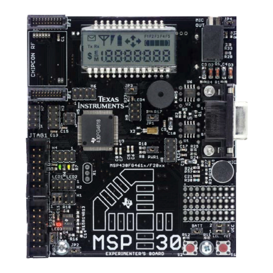
The MSP430FG4618/F2013 experimenter’s board is based on the Texas Instruments ultra-low power MSP430 family of microcontrollers [1, 2]. Residing on this board are the MSP430FG4618 [3] and the MSP430F2013 [4] microcontrollers. 3. Tools Requirement An MSP430 Flash Emulation Tool (MSP-FET430UIF) is required to download code and debug the MSP430FG4618 and MSP430F2013. -
Page 5: Functional Overview
Communication between the two on-board microcontrollers is also possible. In addition, all pins of the MSP430FG4618 are made available either via headers or interfaces for easy debugging. Sample code for this board is available... -
Page 6: Hardware Installation
MSP430 on-board. VCC_1, the bottom row, is for the MSP430FG4618 and, VCC_2 on the top row, is for the MSP430F2013. A jumper placed on the rightmost 2-pins (FET) selects the JTAG FET as the power source. - Page 7 6.1.4 Buzzer A buzzer is connected to a digital I/O port of the MSP430FG4618. It is driven via a port pin of the MSP430. The buzzer can be completely disconnected by using jumper JP1.
- Page 8 CC2500EMK/CC2420EMK at an RF carrier frequency of 2.4 GHz. 6.2.2 RS-232 For a serial interface to a PC, the MSP430FG4618 supports the standard RS-232 9-pin interface via its USCI peripheral configured in UART mode. Standard baud rates for transmission and reception can be configured using in software 6.2.3 I2C/SPI...
- Page 9 6.3.1 Microphone The microphone is connected to the MSP430FG4618 and may be used for various applications. The microphone is enabled/disabled via a port pin connected to the MSP430FG4618. 6.3.2 Analog Filters An active first order high-pass filter (HPF) with a cut-off frequency set at approximately 340Hz follows the microphone to eliminate extremely low input frequencies.
- Page 10 6.4.2 MSP430FG4618 Clock Sources A standard 32.768kHz watch crystal is populated at footprint X2 and sources source ACLK of the MSP430FG4618 for low frequency, ultra-low power standby operation and RTC functionality. The integrated FLL+ clock module provides a programmable internal high frequency clock source for the CPU and other peripherals on-chip.
- Page 11 The software source files are available at the MSP-EXP430FG4618 documentation page at www.ti.com/msp430. 5) The MSP430FG4618 is no longer accessible via JTAG, is something wrong with the device? - Verify that the target device is powered properly...
- Page 12 MSP430xG461x device data sheet, Texas Instruments literature number SLAS508 MSP430x20x3 Device datasheet, Texas Instruments literature number SLAS491 MSP-FET430 Flash Emulation Tool (FET) (for use with IAR v3.x) User's Guide, Texas Instruments literature number SLAU138 MSP430 Interface to CC1100/2500 Code Library, Texas Instruments literature number SLAA325...
-
Page 13: Appendix A Configuring An Iar Embedded Workbench Project
Programming and debug is done using JTAG1 and JTAG2 providing access to the MSP430FG4618 and MSP430F2013 respectively. Steps to program each of these devices are shown in this section. It is assumed that the USB FET tool has been installed using the instructions provided in the FET User’s... - Page 14 4. From the same menu under the Debugger option, select the FET Debugger shown as a snapshot in Figure A-2. Figure A-2: Selecting the FET Debugger 5. Then proceed to the FET Debugger option and choose the Texas Instrument USB-IF as shown in Figure A-3. The default setting of Automatic needs no change.
- Page 15 MSP430F2013 Programming 1. Connect the 14-pin cable to JTAG2 header on the board. 2. Create a new project or load a valid existing project on the IAR Embedded Workbench. 3. In IAR Embedded Workbench under the Project drop-down choose Options; this brings up the menu shown in Figure A-1.
-
Page 16: Appendix B Jumper Locations And Settings
Appendix B Jumper Locations and Settings Figure B-1 represents the location and name of each jumper on the experimenter’s board. Figure B-1: Jumper Locations... - Page 17 AAA batteries either MSP430 Buzzer enabled and connected Buzzer muted Optional to P3.5 of the MSP430FG4618 LED3 enabled and connected LED3 connection Optional / Required for to P1.0 of the MSP430F2013 disabled LED3 use...
-
Page 19: Important Notice
TI as compliant with ISO/TS 16949 requirements. Buyers acknowledge and agree that, if they use any non-designated products in automotive applications, TI will not be responsible for any failure to meet such requirements. Following are URLs where you can obtain information on other Texas Instruments products and application solutions: Products...